coffee
Solar Coffee Roaster Contest

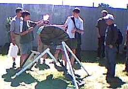
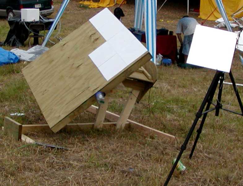
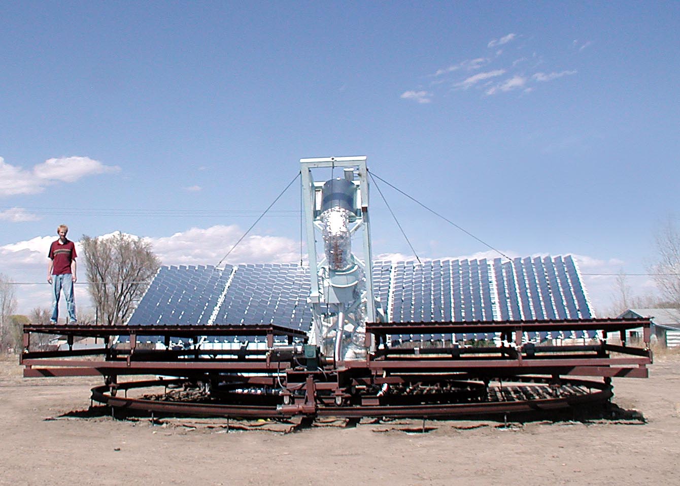
OK, here's a real challenge. These guys, Dave and Mike Hartkop http://www.solarroast.com , have an unusual Coffee roasting business. They have built their solar powered Helios 4 coffee roaster. Essentially a large Fresnel dish on a vertical axis mount.
Up to now they have been manually controlling this dish. Actually this works pretty good as the operator must be on hand to monitor the roasting anyway. Roasting takes 10 to 20 minutes and needs to be adjusted every 2 to 3 minutes. I don't know if I'd have the patience to do this %^)
Now they want to automate the process with a solar tracker. They want someone to devise a solar tracker system to control the Helios 4 roaster. And better yet, they will award the winner with a grand prise of $1000 dollars. There is a $50 entry fee so they can know you are serions. (I would enter except my plate is to full right know, sounds fun.)
If you have questions I'm willing to assist you with your project. I would prefer initial contacts by phone:
(651)583-2265
BTW, I am not affiliated with them in any way. I just like to see cool projects happen.
OK, get your buts in gear and make this happen for them.
Helios 4
About Us:
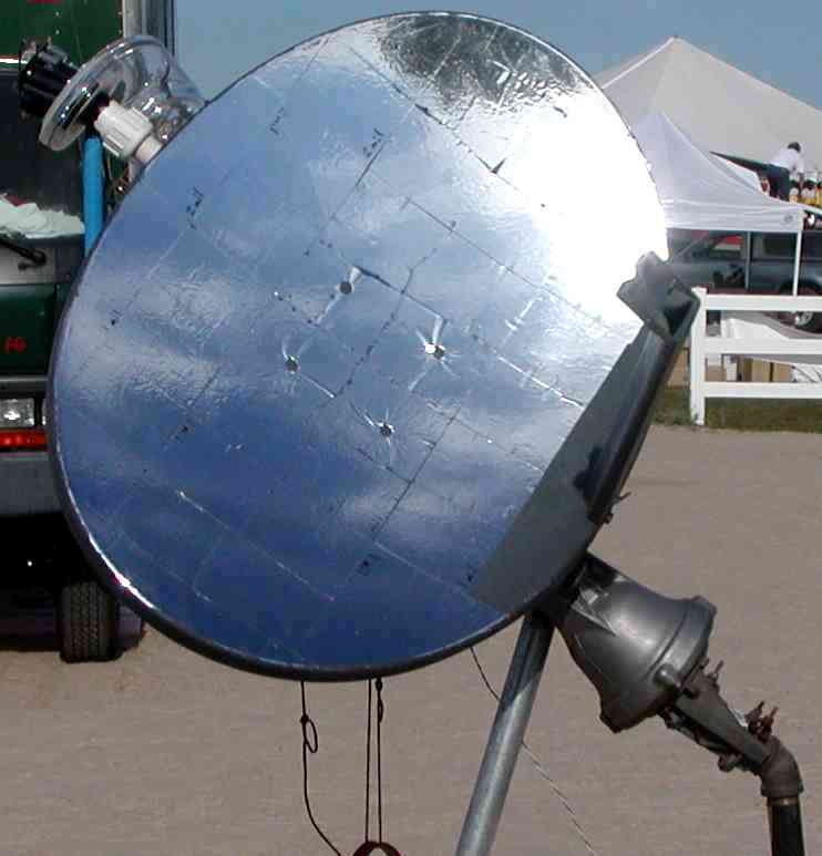
My brother and I, Dave and Mike Hartkop, started our company five years ago. It grew out of a realization we had that we could roast organic coffee directly with solar energy, instead of using natural gas. Our first roaster, the Helios-1, used a satellite dish covered with mirrors and a roaster made from a broccoli strainer! It could roast about 1 pound of coffee in 15-20 min. of solar exposure.
In 2007, we moved from Oregon to southern Colorado in order to take advantage of the nearly year-round solar exposure in Pueblo Colorado. We opened our own retail coffee shop, called "Solar Roast Coffee", and have been in business ever since!
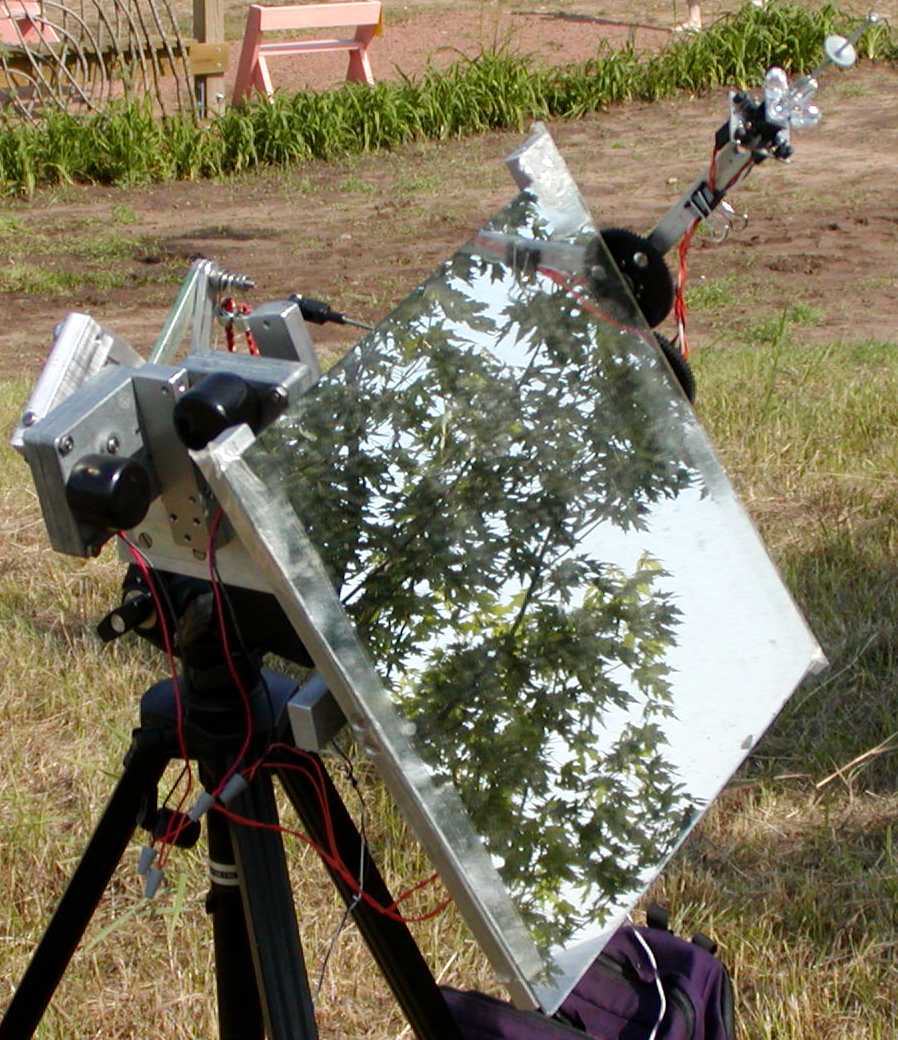
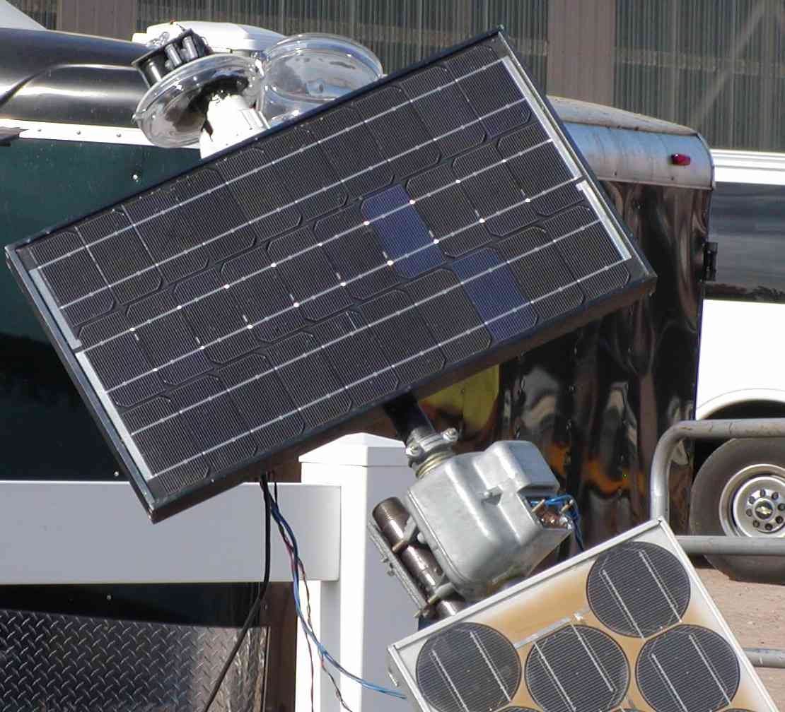
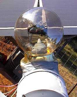
Our newest roaster, the Helios-4, employs a 35-foot wide solar concentrator, which we manually track to follow the sun via a pin-hole targeting camera and switches for up, down, left, and right. The new machine can roast up to 30 pounds of coffee in 15-20 minutes, and is also outfitted with an auxiliary propane burner to augment temperatures on extremely cold or cloudy days. (We DO purchase carbon credits in order to 'offset' the fuel we inadvertently burn.)
About the Contest:
Our contest, the 'Sun Tracker Challenge', directs teams to design and build a solar tracker system. The system must interface with the Helios-4 and will keep it aligned to the sun through an eight-hour roasting day. Entrants can use frame-grabs from our existing video-camera, install their own sensors, or install position encoders and use a timer-based method to accomplish the task! The winning team receives $1000.00 cash an gets a write-up on our web site and local news. The top-ten finalists all receive Solar Roast Coffee prizes, including coffee and T-shirts.
June 10 Final Project Proposals Deadline -your team's project proposal is received. Proposal is just that: a proposal, not a finished project.
June 15 Top Ten Finalists announced -all proposals have been reviewed, ten most workable are chosen.
June 15-August 30 -Ten finalist teams build and test their sun-tracker projects, readying them for practical test in Pueblo.
September 1-30 -Practical Testing of top-ten Projects
October 10 Final Winners Announced -One first place, and prize choices for remaining 9 teams.
Details are online at:
 http://solarroast.com/suntrackerchallenge.html
Interface Details:
Controlling the array movement:
Our control system includes a set of relays that can be driven directly by the team's project. Our control box has a female 5-Pin DIN connector (see image 5pinDIN.jpg) which is addressed as follows:
pin 1  Track toward vertical
pin 2  Track toward horizon
pin 3  Pan Clockwise
pin 4  Pan Counterclockwise
pin 5  Relays Common, floating.
ring   Ground
The internal relays driven are of type:
Siemens # VKP-35F42 relay. Sealed, PC mount power relay for high-current applications. 12 Vdc, 90Ω coil, 130 mA. SPDT contacts rated at 30 Amps. 1.02" x 0.84" x 0.86" high. The system is wired so that opposing directions can not be activated at the same time. See schematic (relaysschem01.jpg) The relay coils are electrically isolated from the control system, and are floating with respect to ground.
Powering your project:
A standard 2-socket 120VAC outlet is provided near the main control box. The outlet is GFCI protected and rated at 20A. Projects are expected to have their own internal fuses (15A or lower) in line with line power supplied. Your project box, to be connected to Solar Roaster Control box, should measure no larger than 18" x 18" x 12", (We need room for bags of green coffee!)
Sensors and cables:
100' cables to reach tower, or to reach horizontal track motor.
Use magnets to affix sensors to the system.
A rotary encoder, if used, should be fitted with ANSI #40 1/2" pitch sprocket, (bicycle chain). You provide encoder with sprocket attached, I will mount it!
Movement and Motors:
The outer Circular track is exactly 35' in diameter. The system is driven by two 90vdc gear motors with electronic speed controls. The speed-presets can be set by adjusting the electronic speed controller knobs internal with the system controls.
Default motor tracking and panning speeds are roughly 3°/sec. The movable array weighs 5300 pounds and is supported on 18 heavy iron casters. Kind of a "Lazy Susan" on steroids. There is minimal mechanical backlash at start and stop, and the system can be controlled manually with switches and targeting camera to an accuracy of +-1/8th°, About 1/2 the Suns image diameter.
An example 'manual controller' schematic of the interface.
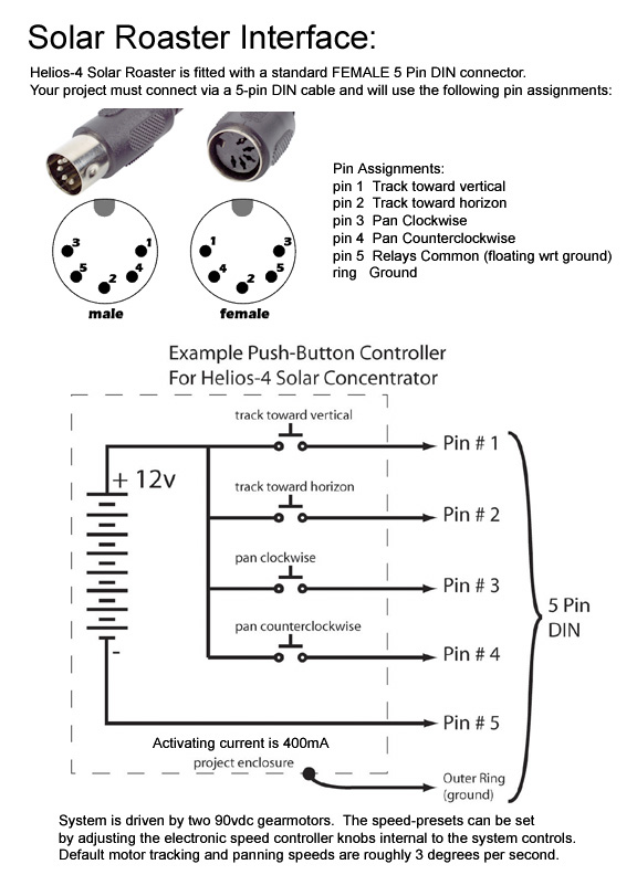
Manual Controller and DIN connector
opensunproject
 * Open Sun Project Stepper Motor.
They have a Weather Proofed Stepper Motor,
carter
 * SunSeeker Project
David Carter's PIC based solar tracker.
Carter uses a method that acquires the sun by alternately panning in azimuth then elevation. The PIC reads output current and finds the maximum. This is done without light sensors just the charging current sensor.
The large servos, similar to radio controlled or RC servos, are driven with a pulse width signal.
The ON time defines the angle.
The OFF time is not critical and should be from 10mS to 30mS.
ON time of 1.0mS =   0°
ON time of 1.5mS =  60°
ON time of 2.0mS = 120°
Interesting idea but not really the best way of tracking the sun. Light sensors work much better.
demartile
 * "Rich DeMartile" <rich_demartile@prodigy.net>
* has a schematic of a solar tracker and mount based on a pair of CdS photo cells.
peterthinks
 * "Peterthinks" <Peterthinks@hotmail.com> has made a solar tracker using RC servos. The system has a tracker based on BEAM technology. The beam circuits powered the RC servos. The tracker used only the power of the sun to move.
tag
 * The Analog Guy Solar Trackers:
ST2-48V5A SINGLE & DUAL AXIS SOLAR TRACKER 56V 5A MAX
ST2-12V DUAL AXIS SOLAR TRACKER 18V 0.5A MAX
One of my competiters.
jamesley
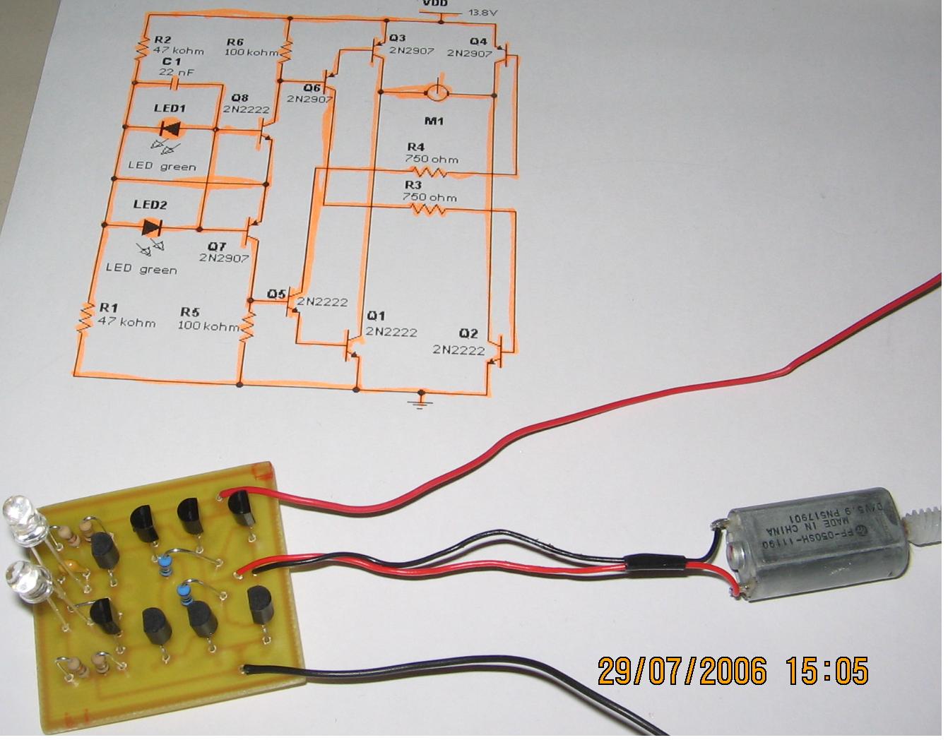
Jamesley Dasse's Solar Tracker
Jamesley made this 2 axis PV solar tracker for a college project. His professor requires that he use a stepper motor drive. I designed a preliminary circuit for him to use. This circuit doesn't have rotation limits yet.
 LED7 Solar Tracker Schematic
relay
cds
Cadmium Sulfide Relay Tracker Schematic.
 CdS1
CdS1
This was about the simplest tracker I knew of until the LEDBlue trackers. It uses a Radio Shack 275-249A relay. Adjust the sensitivity of the CdS cells with a Sharpie permanent marker as described
bellow, in the Chace tracker. The picture tells it all.
This tracker is not as accurate as the electronic tracker but quite sufficient for use with PV panels.
While the proof of concept is good it will burn the relay contacts. This is caused by the relays being turned on or off slowly. It melted the plastic case on the relays.
limitops
How Limit Switches Operate
Limit switches are essential for servo motor operation with solar trackers. I made this diagram to help explain how they work.
Top. Normal operation between limit switches.
Middle. The left limit switch has opened to stop movement to the left. To move to the right again the diode conducts current that allows movement to the right.
Bottom. The right limit switch has opened to stop movement to the right. To move to the left again the diode conducts current that allows movement to the left.
Sellect a diode or rectifier rated at the maximum motor current plus some margine. Also the voltage should be at leat 100V and preferably 200V.
Needles to say, the limit switch must operate before the mechanical limits are reached. If the mechanical stop is reached before the switch the motor can draw quite high currents and can destroy the solar tracker.
led1
LED1 LED Sensor Relay Tracker Schematic.
 LED1
LED1
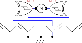 XOR Type Tracker
I'd been looking for truly low cost and yet accurate conventional solar trackers. The CdS tracker is pretty good but lacks accuracy and sensitivity. I was thinking about using PV cells as a photo conductive sensor. I was experimenting with LEDs and noticed they generate voltage in sunlight.
I was thinking of using the LEDs as Photo-Conductive cells, something like PIN Diodes. Basically reverse biasing them and measuring the photo-conductive current. However, my multi meter was going wild. It appeared the LEDs were actively generating current when in sunlight, not just conducting current.
Bingo! This got me to thinking.
They generate quite a bit of voltage. The green ones generate about 2.0V, some as much a 2.25V. Not the piddly .65 volts of a silicon PV cell. How is this so? Well, it turns out green LEDs are made from Gallium Phosphide, a semiconductor with a much higher bandgap voltage.
I thought I had invented the use of LEDs as PV cells as I'd never heard of this effect before in LEDs. Well, after some investigating I found a number of references to this. The guys that had done the most work in this area were the people form the "BEAM" project. They make tiny solar powered robots and some used LED photo sensors.
And of course the venerable Forest Mimms III also knew this.
bandgap
I've been using the term "Band Gap Voltage" loosely for years. Technically this is incorrect. To be fair, band gap voltage is not well defined in the literature either. I apologize to the "Sticklers of Fact", I'm usually one of them, but until I find a better way to describe the voltage generated by various semiconductors I'm going to continue using this term. I am in good company though. Wikipedia artical on Bandgap.
ledvsbandgap
Further investigation finds this:
Color    Type    BGVolts Material
InfraRed Sensor  0.15V   Lead      Sulfide
InfraRed Diode   0.3V    Germanium
InfraRed PV Cell 0.65V   Silicon
InfraRed LED     0.6V    Gallium   Arsenide
Red      LED     1.25V   Gallium   Arsenide Phosphide
Yellow   LED     1.4V    Aluminium Gallium  Indium    Phosphide
Green    LED     2.25V   Aluminium Gallium  Phosphide
Blue     LED     3.0V    Indium    Gallium  Nitride
UV       LED     4.5V    Aluminium Gallium  Nitride
And other colors have similar results.
Note! White LEDs don't work as they don't operate like normal LEDs.
Note! These voltages must be measured with a very high impedance voltmeter. Your standard digital meter won't cut it as they only have an impedance of 10MΩ, which is to low to measure this voltage properly.
An Electronometer has as much as 1000MΩ.
A MOSFET source follower circuit has similar impedance.
Lastly, use direct sunlight as it has a broad spectrum of light from far InfraRed to Ultra Violet and is quite bright.
ledtrackerinvention
I invented the use of LEDs, which have high bandgap voltages, in solar tracker applications in about 1995. I did an extensive search and could not find any prior art. I couldn't find applications that used LED pairs with Op-Amps either.
I had been using a very low threshold MOSFET in a TO-92 package, BS107PT. The threshold is about 1.5Vth. If I put two LEDs back to back, one fighting the other, the one with more light intensity wins and expresses its voltage and polarity. I thought I could use this to switch the MOSFET. And it worked.
By using one LED as a sort of power supply and the back to back pair connected from it to the MOSFET gate the circuit is complete. (This I also have not seen elsewhere.) My implementation uses three "Power Supply LEDs", aimed East, Up, and West. The sensor LEDs are aimed about 90°s from each other and at about ±45°s either side of up. Of course, the easterly LED of the pair will be -45°s and the westerly LED of the pair +45°s to the West. This makes the center have a dead zone of 0 volts where tracking stops.
The circuit is quite sensitive. It brings the panel back to the East just after sun rise. The accuracy is quite good, generally better than ½f° of arc. You can calibrate the sensor by bending or aiming the LEDs a bit.
While the proof of concept relay circuit works it will burn the relay contacts in a similar way to that of the Cadmium Sulfide tracker. This is caused by the relays being turned on or off to slowly causing the contacts to arc. It melted the plastic case on the relays because of the generated heat. To solve this problem a form of hysteresis is needed. I learned a lot from this circuit failure.
My invention is specifically the use of a pair of LEDs or PV Cells connected anti-parallel, (connected back to back), used in solar tracker applications.
how
Additional Description on How This All Works.
 Basic LED Circuit
 Bipolar
 Bipolar
 MOSFET
1. PhotoVoltaic/LED sensors all generate VOLTAGE. However, if there is no load current the voltage is independent of the applied light intensity. I.E, using voltage ALONE doesn't work well for sensing light intensity. Ok, there is a bit of load current caused by leakage current in the PV cells, but leakage current loads are highly dependent on temperature and not very stable. Also, each PV cell has a different leakage current. Not Good!
Theoretically, every photon, with sufficient energy, could knock an electron loose. The charge on this electron is the intrinsic "Band Gap Voltage" of the semiconductor. Approximately 0.65Vbg for Silicon.
Therefore, the voltage is independent of the rate of photon capture.
2. Photovoltaic/LED sensors all generate CURRENT. This current is directly proportional to light intensity. The light intensity vs current is highly linear. Each PV cell generate similar currents, because each element has the same light capture area, and mostly independent of temperature.
Theoretically, the resultant current is directly proportional to the quantity of photons that produce electrons.
The actual current is dependent on the efficiency at which the photons can produce the electrons.
3. When PV cells are connected anti-parallel, as above, the current generated by one PV cell opposes the current generated by the other PV cell. This way there is always a load current. The resultant voltage across the PV cell pair is highly dependent on which cell has greater light intensity.
The voltage change is NOT LINEAR. It changes rapidly near balance going from one maximum polarity to the other quickly around the balance point. When near balance there is great angular sensitivity. It's easy to get better than ±¼° resolution with simple circuits and no optical devices.
4. When away from balance the stronger PV cell dominates the weaker PV cell pulling the voltage closer to its forward biased voltage. Even though away from the balance point the angular sensitivity is still near ±¼°. Of course there is a limit to the voltage. It can't get higher than the bandgap voltage because the current will be shunted by the inherent body diode. This is why it's advantages to use high band gap voltage semiconductors when higher drive voltages are required.
5. The first 2 circuits operate near zero differential voltage whereas the last 2 circuits operate away from zero volts. Transistors have an inherent input bias, 2N3904 = 0.7Vth or ZVNL120A = 1.5Vth. When dark, the voltage across the sensor pair is near zero allowing the transistor to turn off causing the motors to move in the park direction.
6. The 2 LEDs don't, necessarily, need to be of the same type or color. The only requirement is the primary LED needs to generate sufficient voltage to bias the active transistor into conduction. They should both be of similar "Short Circuit Current" generating capabilities.
There is a report from "WORCESTER POLYTECHNIC INSTITUTE" that did some tests on the use of LEDs as sensors for solar trackers.
Their report had an unfavorable result when using LEDs or PVs.
However, in reading the report, I saw their test circuit was not designed well for testing LEDs in light sensor applications.
Their circuit used the LEDs in "voltage mode", as described in 1 above. Not Good.
This caused the unfavorable results compared to Cadmium Sulfide,CdS, cells.
I wish they had contacted me before publishing this report.
Here's the preliminary report: Dual-Axis Solar Tracker: Functional Model Realization and Full-Scale Simulations
Authors: Dante Johnson-Hoyte, Melanie Li Sing How, Myo Thaw, Dante Rossi
And the final report: Dual-Axis Solar Tracker: Functional Model Realization and Full-Scale Simulations
Authors: Myo Thaw, Melanie Li Sing How
They have an image of one of my earlier tracker designs, the LED3, which uses the first circuit, above, driving a Schmidt trigger logic gate.
They didn't cite my circuit in the report.
OK, these were undergraduate students, but come on guys, at least do the basic research.
led2
LED2 LED Sensor Relay Tracker Schematic.
 LED2
LED2
XOR Type Tracker
Circuit 1 tends to chatter the relays under certain lighting conditions as there is no built in hysteresis. This version uses a Schmitt trigger hex inverter circuit to eliminate the chatter. It works better but is more complex.
Note! R4 and R5 are used to force parking when it gets dark. If parking is not desired don't use R4 and R5. Parking may not be desired in low power consumption applications.
Also, the parking resistors, R4 and R5, reduce sensitivity a bit.
ledplcanalog
LED Analog Sensor for use with a PLC.
LEDPLCAnalog
This sensor is a variant of the front end of the LED5.
Many PLCs, Programmable Logic Controllers, have an analog input resistance of 1MΩ, R2.
Others have lower input resistance which should use the LED5PLC.
R1, in the schematic, is used to balance the output to about ½ VCC, 5V in this case with VCC at 10V.
I have tried VCC from 1V to 4V. Pretty much dependent on the limits of the transistor pair. Outside of breakdown voltage the leakage current determines the accuracy.
ledplcanalognp
When the light is balanced the output will be ½ VCC. It will also be ½ VCC when it's dark.
I.e. a "No Park" sensor.
ledplcanalogp
However, if R1 is eliminated the output will be 0V when dark.
I.e. a "Parking" sensor.
led5
led5s5v
LED5S5V Simplified LED low power tracker.
 LED5S5V
I was looking for a much lower cost tracker for low power applications. One of these applications is a small lighting heliostat. This circuit uses small switching transistors. The maximum motor drive current is limited to about 250mA maximum at 5V.
I've tested the circuit on voltages from 3V to 21V. With some component changes it should be useful to 63V in a 36V PV panel system although I haven't tried this yet. With higher voltage and the use of heat sinks on the bridge transistors much higher currents should be possible.
The parts cost is very low. Parts cost estimated using Digikey prices. Ok, you can get stuff from the surplus stores but I will stick with Digikey.
1. 2N2222A NPN  transistor       4 @ $0.21 = $0.84
2. 2N2907A PNP  transistor       4 @ $0.21 = $0.84
3. 430  Ω 1/4 W resistor         2 @ $0.06 = $0.12
4. 5   KΩ 1/4 W resistor         2 @ $0.06 = $0.12
5. 22 nF capacitor               1 @ $0.08 = $0.08
6. LED Green Lumex SSL-LX5093LGT 2 @ $0.12 = $0.24
                                     Total = $2.24
$2.24, is this cheap enough?
led5s12v
LED5S12V Simplified LED low power tracker.
 LED5S12V
This circuit uses small switching transistors. The maximum motor drive current is limited to about 100mA maximum at 12V.
1. 2N2222A NPN  transistor       4 @ $0.21 = $0.84
2. 2N2907A PNP  transistor       4 @ $0.21 = $0.84
3. 1.6 KΩ 1/4 W resistor         2 @ $0.06 = $0.12
4. 47  KΩ 1/4 W resistor         2 @ $0.06 = $0.12
5. 100 KΩ 1/4 W resistor         2 @ $0.06 = $0.12
6. 22 nF capacitor               1 @ $0.08 = $0.08
7. LED Green Lumex SSL-LX5093LGT 2 @ $0.12 = $0.24
                                     Total = $2.36
led5connections
 LED5 Connections
led5forsale
I have the LED5 series trackers for sale.
Yes, I know, not everyone wants to build these from scratch so I made a PC board for the LED5 series.
The single axis board is a bit less than 1/2" x 1" and the dual axis is a bit less than 1" x 1".
led5plc
LED5S12V Modified for use with a PLC.
 LED5S24VPLCDN
The schematic is for the "Pull Down" variant.
This version of the basic LED5 can be used as a sensor input to a PLC, Programmable Logic Controller. The output is an "Open Collector" NPN transistor and assumes the PLC has the associated "Pull Up" resistors.
The actual voltage range is from 4V to 28V. (I can make higher voltage variants also.)
I can also make 24V LED5 trackers with totem pole outputs which have both pull up and pull down transistors. Essentially the same as the standard trackers but with limited drive capabilities.
This circuit does not have a parking function. Parking and Reverse Inhibit functions are best performed in the software of the PLC using timing functions.
Note! If you don't want the passive load resisters, i.e. their already in your PLC, they can be removed by clipping one of the resister leads.
sh
Shipping & handling is $4.00us for any number of trackers or devices in the US.
Shipping & handling is $10.00us for any number of trackers or devices in the outside the US
to almost anywhere in the world.
I accept checks, money orders, and funds in "US DOLLARS ONLY".
Make checks payable to "Duane C. Johnson".
Or use Western Union, http://www.westernunion.com/Home
Just email me the Western Union Money Transfer Control Number (MTCN).
If you entered a query question please give me the correct response answer!
Or use MoneyGram
http://www.moneygram.com
Please don't forget to include:
Your shipping address.
The part numbers and the quantities of what you want me to send to you.
Places I can't ship to:
Jamaica
Mexico
Packages just get "lost".
Use FedEx, UPS, or DHL at about $95us for 6 day service.
Or a private shipping service in the US.
I call these "Smuggler Address".
Problematic shipping to:
Many times Canada takes 6 weeks, especially British Columbia.
I don't accept credit cards.
whatubuilding
What are you building?
Be very specific.
What is the tracking mount type?
Vertical axis, AZimuth/ALTitude? (Generally not recommended)
Horizontal axis? (Usually for parabolic troughs)
Polar axis, Right ASCension/DEClination? (The best)
Possibly a Heliostat mirror?
What is being tracked?
PV Panels?
Thermal Panels?
Dish or Trough Concentrators?
What motors are you using?
How fast do they move?
How much time to move 180 degrees?
How much power do they take?
How much current do they consume?
Where are you located?
The Longitude?
The Latitude?
Postal Address:
Duane C. Johnson
Red Rock Energy
12181 375th St.
North Branch, MN
USA 55056-6799
Email address:
Duane C. Johnson <redrok@redrok.com>
Phone number:
(651)583-2265 days and evenings. Central time zone.
ledblueplc
Another Sensor for use with a PLC.
These sensors work nicely with a PLC input. Either you use the pullup resistor or use the pullup resistors in the PLC.
In the first sensor I used a VN10LP MOSFET which needs a bit more voltage to turn on than can be obtained with just one BLUE LED. A GREEN LED is used to bias the voltage upward about 1.7V or so.
The second sensor uses a ZVNL120A MOSFET which has a bit lower gate threshold voltage of 1.5Vth and can operate using only one BLUE LED.
The first & second sensors have a single ended output.
The output is analog in nature varying from VDD to 0V.
This circuit can be used with very low current motors for solar cooker applications.
The third sensor has differential outputs. This output is either West, East, or in the dead band zone where both outputs are high.
The output is analog in nature varying from VDD to 0V.
Note! The diodes should be types that have a very small but not zero leakage current. In this case I used 1N4148 generic silicon diodes. Don't use low leakage current diodes. If the leakage current is too low residual circuit board leakage currents from VDD can cause the voltage on the gates to float up causing both MOSFETs to turn on. Make sure the PC board is very clean or the encapsulating epoxy is clean and has no conductive characteristics. Normal silicone RTVs are not suitable for use here. OK, Dow does make RTVs that work here but these are not readily available and are expensive.
2l003
 Grainger 2L003 Gear Motor
This is a 12VDC gear motor from Grainger's.
This controller works well with the 2L003.
This motor is an off the shelf motor from Grainger's. Stock number 2L003. It's rated for .45 RPM at 50 In Lbs. The motor current is less than 100mA at 12V and about 50mA at 5V.
tamiya
 Tamiya has a number of Model Gear boxes.
The motors supplied are rated for about 3V. They draw a bit to much current for the 2N2222A-2N2907A driver transistors.
lamble
 LED5
LED5
Stewart Lamble built this version.
He subistuted BD135 (NPN) and BD136 (PNP) transistors.
led555
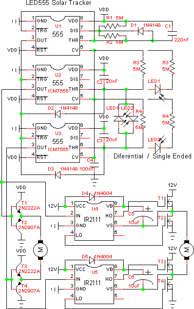
LED555 Timer Based Solar Tracker
Not to be confused with "Timer Based Solar Trackers" which aren't really trackers at all. They just move the mount in a steady slow motion. There is no Sun position feed-back sensing done at all.
This tracker is a bit different from most, if not all, other sensor based solar trackers. Those work by directly measuring voltage, current, or resistance of the light sensor.
This tracker uses the time it takes to charge a capacitor to a voltage. The integration time is directly proportional to the light intensity on the LEDs. This particular solar tracker circuit is based on the venerable 555 TIMER IC. While this example is based on the 555, discrete transistor versions can also be made.
All solar trackers have a characteristic called "Angle Gain Factor", AGF. AGF is the amplification of aiming error angle to the sun to proportionately apply power to drive the motors. The motors are moved in a way to minimize the aiming error angle. More aiming error results in more power to the motor to get back to the minimum error angle.
LED pairs are inherently very sensitive to aiming angle, better than ½° of arc from full power one way to the other.
In the example, U2 and U3 are 555 timer integration circuits.
I usually use:
The ICM7555IN by NXP Phillips which are superior to the NE555 because they are CMOS and have an input leakage current of less than 50pA and can operate from -40°C to +85°C.
The LMC555CN is a bit better because it can output more current, but it costs 5 times as much.
And there are many more clones of the original 555, some in dual and quad packages.
The venerable NE555 also works though it draws draws more current. (BTW, the NE555 is considered the oldest continuously produced integrated circuit, from at least 1972, and still going strong.)
Refer to the timing diagram:
U1 is an astable multivibrator. It periodically sets the timer Flip Flops, FF, in U2 & U3 bringing TRG, TRiGger, low and grounding capacitors C2 & C3 through diodes D2 & D3. When U1 releases timers U2 & U3, by going high, C2 & C3 start integrating charging currents from the sensors. It's a race as to which, U2 or U3, reaches their THR, THReshold, first.
If C3 gets to U3's THR first the output drives the motor forward until C2 catches up, stopping the motor.
If C2 gets to U2's THR first the output drives the motor reverse until C3 catches up, stopping the motor.
If C3 & C2 get to THR at the same time the motor doesn't move at all.
Bright light causes faster charging of both C2 & C3.
If in the dark, charging will be slower. Slow enough so neither C2 nor C3 reach THR.
If even when dark the RC constant of C3 is short enough it will always reach THR and C2 is longer than that of C1 on U1 the motor will move in the parking direction until a Limit switch is reached.
The power supply voltage range of the ICM7555IN is 3V to 16V. I have tested this circuit throughout this range and up to 18V, the maximum allowed voltage.
The sensors I have used ranged from infra red photo diodes to ultra violet LEDs and they all worked fine. I tried CdS photo resistive cells, they worked, but are highly non linear, not so good.
coolsensors
Now something really COOL for the sensors!
I tested it using a pair of 1N270 Germanium point contact diodes as the sensors, worked just fine. I did have to scrape off the paint to let light in.
A pair of 1N4148 switching diodes. That worked too. Cool huh!!!
A pair of small silicon PV cells.
Actually most, if not all, semiconductors of any type are affected by light. Glass packaged diodes, plastic LEDs, ICs with windows, and any other way that allows light to enter affects the semiconductor's characteristics. Usually leakage current or photovoltaic but other things also. No wonder most have black opaque packages. Here is an article about this in EDN magazine. On the dark side by Walter Sjursen.
Technically, diodes D2 and D3 are in the sensor circuit. They too have photovoltaic effects, even with no sensors attached these 2 diodes affect the timing. (It would be best to shield them from light, or paint them black.)
led555leakage
Note! The CREE LED specification says the reverse voltage limit is 5V, other brands are similar as are the silicon photovoltaic cells. Even though this voltage is lower than the supply voltage they still work fine even at 18V, just be aware. Your parts may vary so just test them for reverse leakage current.
led555differential
Differential Sensors:
The single ended circuit simply stops moving when it gets dark, "No-Parking". I wanted to implement "Parking" when it gets dark. In the absence of the LED sensors the charging current is through the resistors. Depending on component values one RC circuit will always charge faster and tend to move in the Park direction.
(Note! Limit switch circuits are required when parking is involved.)
The back to back LED sensor circuit introduces some added differential voltage to the charging capacitors. Again one will win as with the single ended version. An alternate way is to use only one of the pullup resisters, charging current will be sent to the other capacitor through the LED pair. The rest of the circuit operates the same way including PWM.
led555singleended
Single Ended Sensors:
For the first attempt at this concept I used the single ended LED sensor circuits on the right in the schematic.
Note! The series connected resistor and LED sensors are connected to the CONT, CONTrol Voltage, pin. The CONT pin voltage is 2/3rd of Vcc and the same as THR. The LEDs are producers of current which allow the ability to reach THR.
Note! If your using a CdS cell the charge voltage can never reliably reach the THR voltage. CdS cells need to be connected to Vcc.
Capacitors C2 & C3 get charged through the resisters and LEDs. The charging rate is directly proportional to the intensity of light on the sensors and limited by the resisters. (The two resistors, which could be as low as 100KΩ, limit the maximum charging rate, but also limit current if the device shorts out. It's a safety thing.)
When they reach the THR voltage the internal FF is reset.
Of course, one sensor will get to the THR voltage first. The OUT pin voltages of U2 and U3 will be different from each other, one HI one LOW, due to the differences in charging times. As it gets closer to the light balance point the motor drive time duty cycle diminishes to zero. This is a PWM, Pulse Width Modulation, circuit or variable speed motor driver. Cool huh again!!!
led555pwm
PWM
An advantage of this basic circuit type is the output is not analog in nature. It can drive the output transistors into saturation which limits their power dissipation allowing for greater output currents. The analog qualities lay in the PWM nature of the timing. (You might even want to use relays. (I can't believe I Just said that.))
Please note! I have tested these circuits as published. However, your application may need other timing or light sensitivity requirements. By suitably adjusting timing values a great variety of applications can be accommodated.
led555motordriver
Motor Driver
I'm showing a generic 2N2222A/2N2907A low power driver good for a few hundred mA and
a high power MOSFET driver using the International Rectifier IR2111.
Take your pick.
led555parking
Parking:
In most of the other simple solar trackers I've described "Parking" is usually difficult to do, (except for the LED3X trackers).
1. They use a separate sensor to measure the "darkness" and park accordingly. This is not desirable as it adds complexity to the circuit.
2. Add a "weak" imbalance to the sensor circuits to causes motor parking movement when it's dark. This is desirable, if it can be done, as just the primary sensors are used. The problem with those LED sensed circuits is the imbalance resisters need to be 100M or so, not easily done reliably in a commercial product.
One exception is the use of a "leaky" reversed biased diode as in the LEDBlue tracker but this is using an "off spec" characteristic so shouldn't be used commercially.
In these circuits I don't need high especially high resistance, instead I use the imbalance of "Time" in the form of RC, Resister Capacitor, time constants. The timing diagram helps illustrate this. (OK, in the schematic example the two RC constants are shown the same.)
Both Differential and Single Ended versions don't reliably, according to the specs, raise the voltage greater than the THR trip point when in the dark. This is because the charging current is sourced from CV. Which is about the same as THR. To make sure one side always has the ability to move when dark, and you want the parking feature, either R3 or R4 must be connected to Vcc instead of CV.
You might ask, won't this cause an error in tracking angle. The answer is yes. But the the error in bright sunlight is quite small and won't be noticed.
Stepper Motor Driver
This tracker can be used to drive stepper motors. U2Pin(3) and U3Pin(3), the 555 Out Pins, are connected to the Up/Down inputs of suitable counters.
As an example the CD4029 is an Up/Down counter.
Flip Flops
In essence the 555 is a Flip Flop. Why can't this be done with a logic Flip Flop.
It can! It's just that the ubiquitous 555 timers have accurate trip points and are robust circuits.
kapoli
Kapoli
Wow!!! Here's a guy that actually built the LED555 tracker.
 András Kapoli's rendition of the LED555.
Wow!!! Here's a guy that actually built the LED555 tracker.
Thanks Kapoli for showing my circuits work!!!!
led555invention
LED555 my Personal Invention
This is another of my Personal Inventions in the field of solar trackers. I call it "Personal" because I can't find any one else who has developed a similar, not even close, method of using light sensors that produce "PWM" motor driving signals directly. I suspect its a "True Invention" but I didn't want to pursue it. So its in the public domain, I guess.
My other Personal Invention is the use of LEDs as light sensors in Solar Tracker Applications. See:
LED1
ledprop
LED Propeller
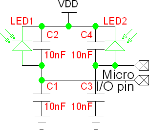 LED Propeller
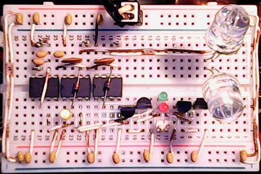
Directly related to the LED555 this generic circuit works nicely with most microprocessors, in this case a Parallax Propeller. The micro doesn't require an analog input, just a simple digital pin that can be rapidly switched from input to output. Although analog inputs can be useful.
This circuit can operate from at least 1V to 28V dependent on the limitations in the sensor voltage rating.
If you have digital pins:
1. Switch pins to output and write them low to discharge the capacitors to ground.
2. Switch pins to input mode to allow the sensors to charge the capacitors. Time how long it takes to go high on each pin.
The one to gets high first wins indicating it has greater light intensity.
The time difference indicates the difference in intensities and can be used to control how fast or long to drive the motor.
If you have analog input pins:
1. Switch pins to output and write them low.
2. Switch to analog input mode to allow the sensors to charge the capacitors. Wait for a predetermined time.
3. Measure the voltage on each pin.
The voltages on each pin indicates the absolute light intensities.
The differential voltages on the pins indicates the difference in intensities and can be used to control how fast or long to drive the motor.
ledse
SE Solar Tracker Consumes Ultra Low Power
 LEDSE
LEDSE
I needed a special solar tracker that would consume extremely low power from a very small PV panel yet be capable of delivering quite high currents to a motor load.
I apologize for not presenting this unusual and innovative solar tracker circuit sooner. It was designed in about 2004 and a PC board was made. As with other trackers I've made the dual axis version was done on a 1" square PC board. This board can be cut in half for a single axis version that is 1"x.5". While I have a bunch of these boards the circuit is very time consuming to assemble so this tiny tracker on the tiny PC board is not cost effective to build or for me to sell.
I'm a member of a "Beam" robotics group who do similar things with Solar Engines, or "SE", circuits. This particular SE type is based on the venerable MN1381 Voltage Monitor chip. Click here to see a description of how they work..
My test example used an older version of the MN1381 the MN1281 but it works the same. The MN1281 has a bit higher leakage current though. The exact part# of mine is "MN1280-L" in an unusual "M" package and has a CMOS output. I have the "L" version which triggers at 3.0V to 3.3V and has a hysteresis of 100mV to 300mV. This cool circuit can consume currents as low as 50µA, or lower, which charges accumulator capacitor C5. When the MN1381 fires it couples a voltage increase to the MOSFET gates through the caps C1 & C2.
A voltage difference in the two caps is caused by the sensor LEDs, however there is not enough voltage to turn on the MOSFETs. The pulse from the MN1381 IS high enough though. One of the MOSFETs will turn on harder and win causing the motor to move and discharge the accumulator capacitor. If the light is balanced both sides will fire, the motor will not move, and discharges the accumulator capacitor.
ledac
LEDAC a Very Simple Solar Tracker Powered by an AC Power Source
LEDAC1
This circuit, if powered by a low voltage AC power source, can drive a reversible permanent magnet DC motor. Basically the motor, tracker, and the AC source are connected in series in any order. As far as I can tell this is got to be the simplest conventional solar tracker that can follow the Sun in both directions and do it accurately. It has only 6 parts, 2 MOSFETs, 2 diodes, and 2 BLUE LEDs.
For a more complete description of the operation and the requirements of the diodes see the LEDBlue bidirectional solar tracker circuit.
For more current you can use the IRF3708 MOSFET.
True, solar cooker solar trackers can have fewer parts, as low as 3 parts, but these only track in one direction, to the West.
mosfetssr

|
The LEDAC1 is directly related to MOSFET based Solid State Relays or SSRs.
Unlike these SSRs, which turn on or off the MOSFET switches simultaneously,
this tracker operates them differentially. Essentially rectifying the AC source
for a pulsed half wave current output of either polarity depending on which
MOSFET is on.
These MOSFET based SSRs can benefit from the use of BLUE LEDs and
low Vth MOSFETs. You could set them up to turn the MOSFETs on
simultaneously in the conventional way or operate them individually.
Or just optically isolate a single MOSFET.
|
Note! These circuits depend on the reverse body diode inherent in MOSFETs. That's the arrow in the MOSFET symbol. Essentially, this allows conduction from the source to the drain in the opposite direction to the normal flow through the MOSFET.
This LEDAC1 circuit depends on a very low gate threshold voltage MOSFET. In this case the ZVNL120A MOSFET, 1.35Vth. Yes, this transistor operates correctly in the circuit but the motor needs to be very small, maybe less than 25mA or so. What is need is a power MOSFET with similar or lower Vth.
Clearly the IRF3708 1.67Vth, RFP30N06LE 1.75Vth, and IRLZ44N 1.76Vth are the best power transistors with IRLI2203N 2.01Vth a close forth.
cooker
ledcooker
Solar Cooker Solar Trackers
This is an example made by Small Power Systems.
Solar cookers usually don't require a tracker that moves in both in directions. The person operating the cooker simply resets the cooker to the East when loading the food. The tracker then drives to the West stopping when aimed at the Sun.
The great simplification to these designs is the elimination of the H-bridge in the output circuit. These only need a single MOSFET transistor to drive the motor. Cool huh!!!
LEDCooker1 was designed several years ago, mayby 10 years or so (2001), using the IRLZ44N logic level MOSFET, $1.67 55V 47A 22mΩ 1.76Vth. Basically designed before cheap BLUE LEDs were available. I had experimented with the BLUE ones but abandoned the project because the circuit seemed too expensive for solar cookers, especially for 3rd world applications.
I just revisited these designs as a request from one of my customers. LEDCooker2 satisfies my requirement for low parts cost at about $3us. Can I improve this further?
Instead of the 10mm Lumex LEDs I usually use, which are more expensive, I changed to 5mm types and the newer IRLI2203N MOSFET, $1.70 30V 61A 7mΩ 2.01Vth. Even better, its in a TO-220 Fullpack package, which means the heatsink tab is insulated. The hole in the MOSFET can be used for mounting to the cooker, or a heatsink for driving larger motors, without regards to electrical connections and shorts. I.e. the whole circuit is floating.
OK, for the absolute lowest cost one can use the 3 color version. I probably would choose to use BLUE for all three LEDs because of the greater bias voltage for more safety margin especially in high ambient temperature locations.
I like the CREE high brightness 20mA LEDs.
 Look for the "CN" 30° no stand off types. These have water clear cases. I would suggest the CREE C503B-BCN.
An even lower cost and parts count solar cooker tracker can be made with a TO-92 package ZVNL120A MOSFET, $0.78 200V 180mA 10Ω 1.35Vth. This circuit requires LED2 to be BLUE and LED1 can be any color even infra red types will work. Both LEDs are required to obtain a balance point. Of course the ZVNL120A would only work with quite small motors. A possibly better use is as a solar sensor.
I should say that a single BLUE LED can be used as an absolute light sensor though.
ledcooker3
LEDCooker3
And improved even further, the LEDCooker3 uses the RFP30N06LE MOSFET, $1.09 60V 30A 47mΩ 1.75Vth. I've tested about 100 of these and directly measured the Vth to be 1.72VGS @ 5mA. Clearly the 2.25V generated by the BLUE LED can respectably drive this MOSFET. The total parts cost including a connector is $2.31us.
Cool Huh!!!
An even better MOSFET is the IRF3708 at $1.74us.
1.57Vgs = 30Ω, 1.67Vgs = 3Ω
And the CREE C503B-BCN Blue LED.
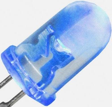
ledblue
Bidirectional Analog Solar Tracker or Sensor.
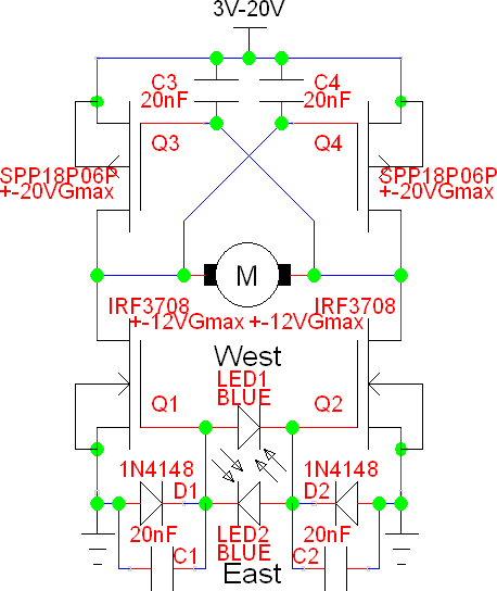
LEDBlueN1
Bidirectional version of the LEDCooker3
When powered from a DC power source, as opposed to the AC power source of the LEDAC, one needs an H-Bridge output. In this case the low side MOSFETs are N channel IRF3708s and the high side uses P channel SPP18P06Ps.
The pair of BLUE LEDs generate a differential voltage applied to the gates. The diodes cause these voltages to always be above ground. If one side is higher than the other one IRF3708 MOSFET turns on harder and and enables the SPP18P06P MOSFET on the opposite corner to also turn on causing the motor to turn. Of course, if the differential voltage is the other way the motor also turns the other direction.
Don't substitute the IRF3708 it is essential because it has a very low gate threshold voltage.
Ok, now there are a couple of other MOSFETS from which one can choose.
Listed in order of lowerst VTH first:
1. ZVNL120A in a TO-92 package.
2. IRF3708 in a TO-220 package.
3. ZVN2106A in a TO-92 package.
4. RFP30N06LE in a TO-220 package.
5. IRLZ44N in a TO-220 package.
And a few others I have not yet tested. See a full list.
Also look at the IRLIB9343PbF P-Channel MOSFET which has a lower gate voltage than the SPP18P06P.
This circuit requires a small bias current to be pulled out of the MOSFET gates to compensate for the leakage currents going into the gate from the positive supply which could cause both MOSFETs to be turn on, a bad thing. A pair of resistors could be connect from the gates to the emitters to absorb the approximately 20nA of leakage current. Unfortunately, I can't obtain low cost resistors in the 100MΩ or more range. A better way is to use diodes that have more leakage current than the MOSFET gates.
The 1N4148 universal high speed switching diode has about 20nA of leakage current, more as the temperature goes up. I tested several hundred of these and all worked well in the circuit. The reason normal 10MΩ resistors don't work is they consume more current than can be supplied by the BLUE LEDs.
Low leakage diodes such as the BAS416 don't work in this circuit because the leakage current is to low.
ledblueplC2
This is a variation that has pull up resistors instead of high side MOSFETs for use as a sensor for PLC or other electronics.
It uses a pair of ZVNL120A MOSFETs.
Notice this is essentially the same circuit as the LEDAC except with 3 terminals instead of 2.
ledfast
LEDFAST Acting Analog Solar Tracker.
 LEDFAST
I needed a special solar tracker that is very fast acting. The action needed to move a PV panel from lock to lock in a few seconds. It was important that little overshoot occur. This circuit satisfies these requirements.
1. R7/R8 form a voltage divider to produce a voltage of 1/2 of VDD and applied to the non inverting inputs of the OpAmps.
2. The OpAmps are setup to have a gain of 1000X through R3/R1 and R4/R2. Capacitor C1/C2 limit the high frequency response of the circuit to prevent oscillations.
3. The LED sensor circuits need to be high impedance so are isolated from the gain resistors through resistors R5 and R6.
4. I use large 10mm "GREEN" LEDs with clear cases. They are made by Lumex, but all normal LEDs can work. (Don't use the White LEDs as they are not normal types.) The LEDs act as small photo voltaic generators. Since LED1 & LED2 sensors are connected back to back the sensor that has the greater light intensity expresses its voltage over that of the sensor with lessor light intensity. Imbalance in the light on the sensors produces a differential voltage which is amplified and presented to the motor. As the light approaches balance the motor differential voltage approaches zero resulting in no motor current.
5. The LM324 has an output current drive capability of >10mA. Transistor pairs Q1/Q2 & Q3/Q4 form unity voltage gain emitter follower current gain amplifiers. With power transistors that have a gain of 100 the motor drive current can be about 1A or more.
6. VCC can be from about 6V to an absolute maximum of 32V. Other OpAmps can be used for a greater VCC range.
7. Note! Limit switches are required in the motor circuits. See:
How Limit Switches Operate.
8. There has to be a down side though. This is a true analog circuit that drives the output transistors in a linear manor therefore power is wasted when slowing the motors. Heat sinks may be required.
9. This circuit is not generally suitable for use with normal high efficiency solar tracking applications. It is best suitable for school projects.
led3
LED3 LED Sensor Electronic Tracker with H-Bridge Drive.
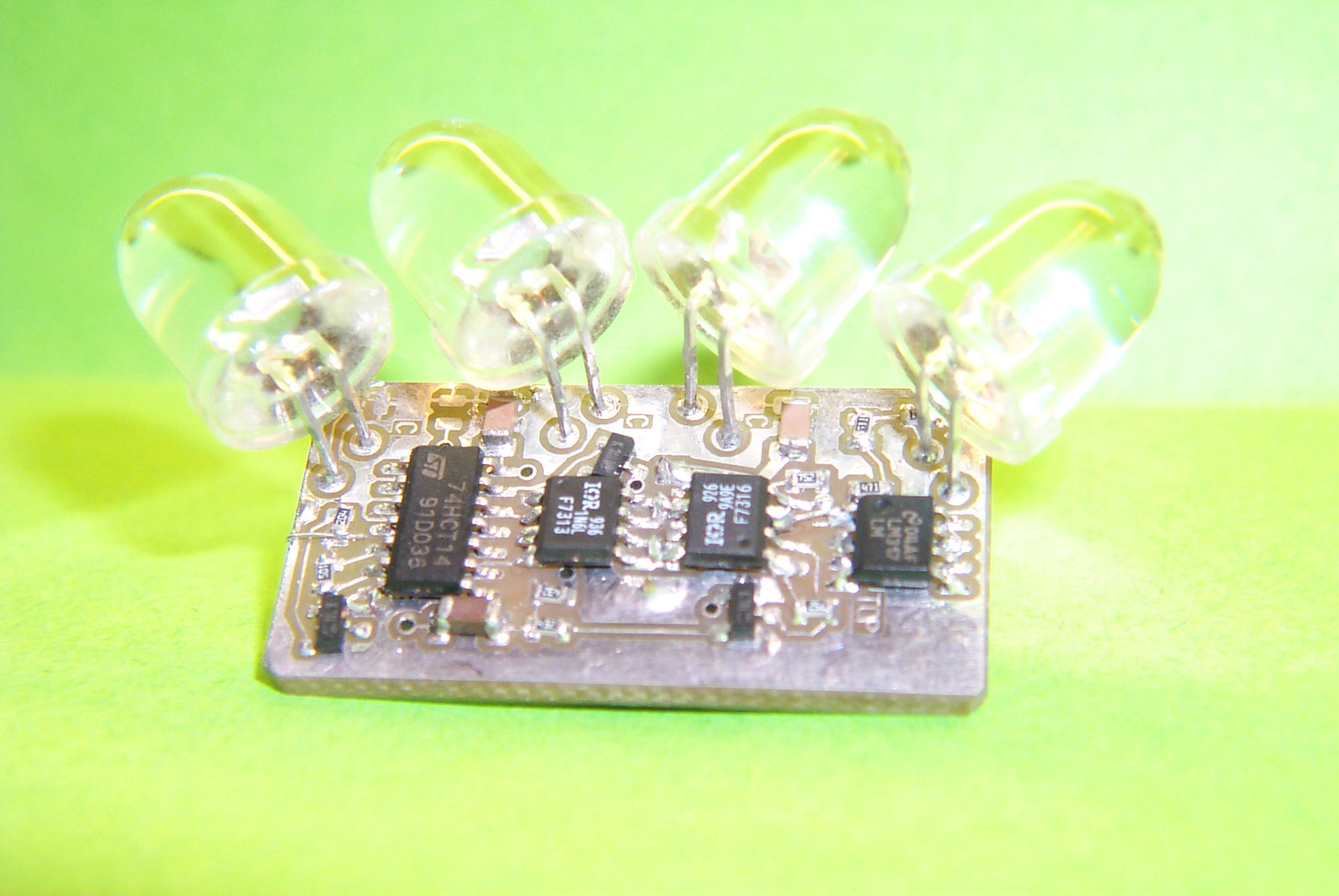 LED3
LED3
XOR Type Tracker
I decided to make a commercial surface mount PC board using the LED2 sensor concept. It is quite sensitive and can track to a few degrees of accuracy in bright sunlight. If a shadow blocker is used the resolution is better then ±1/4°, the diameter of the sun, that's about as good as you can get with an active feedback sensor. The board is a tiny .7"x1.4".
Note! I have replaced the LED3 with the much more capable LED3X series of solar trackers. See below.
This circuit uses power MOSFET drivers and is designed to operate satellite dish linear actuators, however most any DC motor can be used. The power drivers are capable of delivering about 10 amps of peak current, maybe more. When better transistors become available this current can be increased. The drivers operate the actuators in pulses of about .3 second every 3 seconds or a 10% duty cycle. This eliminates the needed for a heat sink on the transistors. Neat huh!
I haven't decided if 10% is the best duty cycle to use. Less will make the tracking slower but, we don't need speed anyway. I will determine this when I get better weather. Slow tracking speed helps in partly cloudy condition. This prevents the tracker from making unnecessary movements when clouds move by.
No electrical adjustments are required. The LEDs can be mechanically adjusted for optimum tracking performance by aiming them after the circuit board is mounted.
led3shadow
To improve accuracy, ie. with concentrators such as troughs or dishes, a blocking shadow can be placed in front. The shadow just covers the two inner LEDs when aimed at the sun. Similar to the shadow on the Chace Tracker.
I have used a band of metal about .5" in width at about 6" from the LED3. If the LED3 is used for E-W tracking the band is oriented N-S. Conversely, if the LED3 is used for N-S tracking the band is oriented E-W. The shadow device is not particularly critical. For instance, I have used black electrical tape on the weather dome and it worked well.
led3specifications
| Power Supply Voltage | 8 Volts to 22 Volts inclusive.
The 8V minimum is specified to prevent damage to the MOSFET power drivers. The damage is due to operating them in the linear region with a load. This causes excessive power to be dissipated in the MOSFET with a resultant damaging temperature rise.
The 22 volt maximum is defined by the voltage tolerance of 24V protection zener. This zener protects the power MOSFETs from seeing damaging breakdown voltages. During testing I had several failures when operating from a car battery while the alternator was running. It was determined that the alternator was producing voltage spikes in excess of the 30V breakdown specification of the MOSFETs.
The 24V zener has an initial tolerance of 5%. So the maximum continuous voltage that can be applied before conduction can occur is 22.8V or so.
Most PV panels don't output more than 22V in open circuit. You should check for sure. If they do go to high in voltage a simple power regulator should be added to limit the maximum voltage.
|
| Load Current Continuous | 5 Amp resistive.
The power MOSFETs are rated at over 10A at 25°F. A conservative derating of 50% is prudent especially in hot weather conditions.
|
| Load Current Intermitant | 10 Amp intermitant at 10mS width once per timing cycle.
The Power MOSFETs have an absolute maximum current rating of 30A, but this is with ideal conditions where the temperature is 25°F and very fast gate rise times. The LED3 has a relatively slow gate rise time and may be operated at quite high temperatures sue to the weather. I think 10A at about 10mS is adequate for normal tracking applications.
If higher current motors are required a power amplifier may be needed. See:
http://www.redrok.com/electron.htm#power
I should note that the satellite dish actuator I use normally consumes about 290mA of current at 13.8VDC. This actuator is capable of driving a 15' dish with 1500lb of force. You don't need a high powered drive, just a slow forceful one.
Think slow!
|
| Operating Temperature | -40°F to 185°F or -40°C to 85°C
|
semiconductor
Parts with which I've Used, Tested, or have an Interest.
Note!
VGS Values are measurements I have made on real parts.
Other entries are from the data sheets.
In general the entries are sorted by VGS, Vth, RDSon, and then VDS
mosfet
nch |
-----2 | -----3 | -----4 |
5----- | 6----- | -----7 |
8----- | -----9 | 10---- |
11---- |
IRFB59N10D
10V |
100V |
59.00A |
25mΩ |
10.0VGS=25mΩ
5.50VGS(th)@250µA
18S@35A
Qg=114nC@10V 80V 34.5A |
Single |
N-CH |
TO-220,
TO-262 |
100V Zener
+-30V Gate |
|
$2.99 |
IRFP460
10V |
500V |
20.00A |
270mΩ |
10.0VGS=270mΩ
4.00VGS(th)@250µA
13S@12A
Qg=210nC@10V 400V 20A |
Single |
N-CH |
TO-247 |
500V Zener
+-20V Gate |
|
$6.28 |
IRF840
10V |
500V |
8.00A |
850mΩ |
10.0VGS=850mΩ
4.00VGS(th)@250µA
4.9S@4.8A
Qg=63nC@10V 400V 8A |
Single |
N-CH |
TO-220 |
500V Zener
+-20V Gate |
|
$2.79 |
IRFU310
IRFR310
10V |
400V |
1.70A |
3.6Ω |
10.0VGS= 3.6Ω
4.00VGS(th)@250µA
0.97S@1.0A
Qg=12nC@10V 320V 2.0A |
Single |
N-CH |
IPAK
DPAK |
+-20V Gate
150°C |
|
$1.66
IPAK 100 |
IRFU214
IRFR214
10V |
250V |
2.20A |
2.0Ω |
10.0VGS= 2.0Ω
4.00VGS(th)@250µA
0.80S@1.0A
Qg=8nC@10V 200V 2.7A |
Single |
N-CH |
IPAK
DPAK |
+-20V Gate
150°C |
|
$1.54
IPAK 100 |
IRFU210
IRFR210
10V |
200V |
2.60A |
1.5Ω |
10.0VGS= 1.5Ω
4.00VGS(th)@250µA
0.80S@1.0A
Qg=8.2nC@10V 160V 3.3A |
Single |
N-CH |
IPAK
DPAK |
+-20V Gate
150°C |
|
$1.07
IPAK 100 |
FQP46N15
(LED3X48V
Standard
MOSFET)
10V |
150V |
45.60A |
42mΩ |
10.0VGS=42mΩ
4.00VGS(th)@250µA
33S@23A
Qg=110nC@10V 120V 45.6A |
Single |
N-CH |
TO-220 |
+-25V Gate |
|
$2.08
TO220 100 |
STP40NF12
10V |
120V |
40.00A |
32mΩ |
10.0VGS=32mΩ
4.00VGS(th)@250µA
40S@20A
Qg=80nC@10V 80V 40A |
Single |
N-CH |
TO-220 |
120V Zener
+-20V Gate
175°C |
|
$1.87
TO220 100 |
IRF540N
10V |
100V |
33.00A |
44mΩ |
10.0VGS=44mΩ
4.00VGS(th)@250µA
21S@16A
Qg=71nC@10V 80V 16A |
Single |
N-CH |
TO-220 |
100V Zener
+-20V Gate
175°C |
|
$1.79 |
IRF530N
10V |
100V |
17.00A |
90mΩ |
10.0VGS=90mΩ
4.00VGS(th)@250µA
12S@9A
Qg=37nC@10V 80V 9A |
Single |
N-CH |
TO-220 |
100V Zener
+-20V Gate
175°C |
|
$1.69 |
IRF520N
10V |
100V |
9.70A |
200mΩ |
10.0VGS=200mΩ
4.00VGS(th)@250µA
2.7S@5.7A
Qg=25nC@10V 80V 5.7A |
Single |
N-CH |
TO-220 |
100V Zener
+-20V Gate
175°C |
|
$1.23 |
IRF510
10V |
100V |
5.60A |
540mΩ |
10.0VGS=540mΩ
4.00VGS(th)@250µA
1.3S@3.4A
Qg=8.325nC@10V 80V 5.6A |
Single |
N-CH |
TO-220 |
100V Zener
+-20V Gate
175°C |
|
$0.96 |
NDP708
10V |
80V |
60.00A |
25mΩ |
10.0VGS=25mΩ
4.00VGS(th)@250µA
16S@30A |
Single |
N-CH |
TO-220,
T0-262AB |
80V Zener
+-20V Gate
175°C |
|
$?.?? |
IRF2708
10V |
75V |
82.00A |
13mΩ |
10.0VGS=13mΩ
4.00VGS(th)@250µA
38S@43A
Qg=160nC@10V 60V 43A |
Single |
N-CH |
TO-220,
T0-262AB |
75V Zener
+-20V Gate
175°C |
|
$2.78 |
IRFZ48V
10V |
60V |
72.00A |
12mΩ |
10.0VGS=12mΩ
4.00VGS(th)@250µA
35S@43A
Qg=110nC@10V 48V 72A |
Single |
N-CH |
TO-220 |
60V Zener
+-20V Gate
175°C |
|
$2.13 |
RF1S50V60
10V |
60V |
50.00A |
22.0mΩ |
10.0VGS=22mΩ
4.00VGS(th)@250µA
35S@70A
Qg=150nC@20V 48V 50A |
Single |
N-CH |
TO-262AA
TO-220
TO-247 |
60V Zener
+-20V Gate
175°C |
|
$?.?? |
MTP50N06V
10V |
60V |
42.00A |
28mΩ |
10.0VGS=28mΩ
4.00VGS(th)@250µA
16mS@20A
Qg=70nC@10V 49V 42A |
Single |
N-CH |
TO-220 |
60V Zener
+-20V Gate
175°C |
|
$?.?? |
IRFZ34
10V |
60V |
30.00A |
50mΩ |
10.0VGS=50mΩ
4.00VGS(th)@250µA
9.3S@18A
Qg=46nC@10V 48V 30A |
Single |
N-CH |
TO-220 |
60V Zener
+-20V Gate
175°C |
|
$1.38 |
IRF1405
10V |
55V |
169.00A |
5.3mΩ |
10.0VGS=8.0mΩ
4.00VGS(th)@5.3mµA
69S@110A
Qg=260nC@10V 44V 101A |
Single |
N-CH |
TO-220 |
55V Zener
+-20V Gate
175°C |
|
$3.02 |
HRF3205
10V |
55V |
100.00A |
8.0mΩ |
10.0VGS=8.0mΩ
4.00VGS(th)@250µA
?S@?A
Qg=170nC@10V 44V 59A |
Single |
N-CH |
TO-220AB
DPAK |
55V Zener
+-20V Gate
175°C |
|
$?.?? |
IRFU024
IRFR024
5V |
55V |
17.00A |
75mΩ |
3.57VGS=30Ω
3.85VGS=3.0Ω
4.50VGS=230mΩ
10.0VGS= 75mΩ
4.00VGS(th)@250µA
4.5S@10A
Qg=20nC@10V 44V 10A |
Single |
N-CH |
TO-251
IPAK
DPAK |
55V Zener
+-20V Gate
175°C |
IRFU024 Ron vs. Vgs |
$1.05
IPAK 100 |
IRFZ14
5V |
60V |
10.00A |
200mΩ |
3.42VGS=30Ω
3.75VGS=3.0Ω
4.50VGS=470mΩ
10.0VGS=200mΩ
4.00VGS(th)@250µA
2.4S@6A
Qg=11nC@10V 48V 10A |
Single |
N-CH |
TO-220 |
60V Zener
+-20V Gate
175°C |
IRFZ14 Ron vs. Vgs |
$0.92 |
IRFZ44N
5V |
60V |
55.00A |
16.5mΩ |
3.38VGS=30Ω
3.56VGS=3.0Ω
4.50VGS=41mΩ
10.0VGS= 17mΩ
4.00VGS(th)@250µA
24S@31A
Qg=67nC@10V 48V 51A |
Single |
N-CH |
TO-220 |
60V Zener
+-20V Gate
175°C |
IRFZ44N Ron vs. Vgs |
$1.68 |
PSMN017-80PS
(LED3X24V
Standard
MOSFET)
5V |
80V |
50.00A |
17mΩ |
3.21VGS=30Ω
3.30VGS=7.5Ω
3.39VGS=3.0Ω
4.50VGS=19mΩ
10.0VGS= 17mΩ
4.00VGS(th)@1mA
58S@25A
Qg=26nC@10V 40V 25A |
Single |
N-CH |
TO-220AB |
Reverse Diode
+-20V Gate
175°C |
PSMN017 Ron vs. Vgs |
$1.13 |
IRF3315
5V |
150V |
27.00A |
70mΩ |
3.14VGS=6Ω
3.21VGS=3.0Ω
3.30VGS=1.5Ω
4.50VGS=100mΩ
10.0VGS= 70mΩ
4.00VGS(th)@250µA
11.4S@12A
Qg=95nC@10V 120V 12A |
Single |
N-CH |
TO-220 |
120V Zener
+-20V Gate
175°C |
IRF3315 Ron vs. Vgs |
$1.86 |
IRF7313
5V |
30V |
4.00A |
29mΩ |
4.50VGS=46mΩ
10.0VGS=29mΩ
3.00VGS(th)@250µA
14S@5.8A
Qg=33nC@10V 15V 5.8A |
Dual |
N/N-CH |
SO-8 |
30V Zener
+-20V Gate
150°C |
|
$2.37 |
IRF740
5V |
400V |
10.00A |
550mΩ |
2.96VGS=30Ω
3.23VGS=3.0Ω
3.30VGS=2.2Ω
4.50VGS=580mΩ
10.0VGS=550mΩ
4.00VGS(th)@250µA
7S@6A
Qg=43nC@10V 320V 10.7A |
Single |
N-CH |
TO-220 |
400V Zener
+-20V Gate
150°C |
IRF740 Ron vs. Vgs |
$?.?? |
IRLR2905
5V |
55V |
42.00A |
23mΩ |
2.65VGS=30Ω
2.70VGS=11Ω
2.80VGS=3.0Ω
3.30VGS=94mΩ
4.50VGS=24mΩ
4.50VGS=23mΩ
5.00VGS=20mΩ
10.0VGS=14mΩ
3.00VGS(th)@250µA
25S@36A
Qg=35nC@5V 44V 36A |
Single |
N-CH |
DPAC
IPAC |
55V Zener
+-16V Gate
175°C |
IRLR2905 Ron vs. Vgs |
$1.55
DPAK 100
|
VN2406
3.3V |
240V |
0.19A |
10000mΩ |
2.50VGS=10Ω
10.0VGS= 6Ω
2.00VGS(th)@1mA
300mS@500mA |
Single |
N-CH |
TO-92 |
+-20V Gate
150°C |
|
$0.29
BG Micro |
2N7000
3.3V
"Junk Box Must Have" |
60V |
0.20A |
5300mΩ |
2.49VGS=30Ω
2.70VGS=10Ω
3.29VGS=3.0Ω
4.50VGS=1.8Ω
4.50VGS=5.3Ω
10.0VGS=5.0mΩ
3.00VGS(th)@1mA
100mS@200mA
Qg=1nC@5V 25V 0.5A |
Single |
N-CH |
TO-92,
SOT-23 |
Reverse Diode
+-20V Gate
150°C |
2N7000 Ron vs. Vgs |
$0.42
TO92 1000 |
2N7002
3.3V |
60V |
0.30A |
5300mΩ |
5.00VGS=5.3Ω
10.0VGS=5.0mΩ
2.50VGS(th)@250µA
100mS@200mA
Qg=1nC@5V 25V 0.5A |
Single |
N-CH |
SOT-23 |
Reverse Diode
+-30V Gate
150°C |
|
$0.41 |
BUK965R8
5V |
100V |
120.00A |
5.8mΩ |
5.00VGS=5.8mΩ
2.45VGS(th)@1mA
250S@75A
Qg=133nC@5V 80V 25A |
Single |
N-CH |
D2PAK |
100V Zener
+-10V Gate
175°C |
|
$3.38
D2PAK 25 |
ZVN3306A
5V |
60V |
0.30A |
5000mΩ |
10.0VGS=5Ω
2.40VGS(th)@1mA
150mS@500mA
Qg=1.6nC@5V 16V .8A |
Single |
N-CH |
TO-92 |
+-20V Gate
150°C |
|
$0.78 |
VN2106
5V |
60V |
0.30A |
6000mΩ |
5.00VGS=6Ω
10.0VGS=4Ω
2.40VGS(th)@1mA
100mS@500mA |
Single |
N-CH |
TO-92 |
+-20V Gate
150°C |
|
$0.72 |
IRLB8721
5V |
30V |
62.00A |
16mΩ |
4.50VGS= 16mΩ
10.0VGS=8.7mΩ
2.35VGS(th)@25µA
35S@25A
Qg=13nC@4.5V 15V 25A |
Single |
N-CH |
TO-220AB |
Reverse Diode
+-20V Gate
175°C |
|
$1.27 |
VN2222LL
3.3V |
60V |
0.23A |
7500mΩ |
2.15VGS=30Ω
2.70VGS=6.7Ω
3.30VGS=4.6Ω
4.50VGS=3.6Ω
5.00VGS=7.5Ω
10.0VGS=7.5Ω
2.50VGS(th)@1mA
100mS@500mA |
Single |
N-CH |
TO-92 |
Reverse Diode
+-20V Gate
150°C |
VN2222LL Ron vs. Vgs |
$0.57
TO92 100 |
TF2618L
(AOTF2618L)
3.3V
"Junk Box Must Have" |
60V |
23.00A |
19mΩ |
2.15VGS=30Ω
2.25VGS=3.0Ω
2.70VGS=67mΩ
3.30VGS=16mΩ
4.50VGS= 9mΩ
10.0VGS=19mΩ
2.50VGS(th)@250µA
45S@20A
Qg=10nC@4.5V 30V 20A |
Single |
N-CH |
TO-220F
FULLPAK
Insulated |
Reverse Diode
+-20V Gate
175°C |
TF2618L Ron vs. Vgs |
$0.95
TO220F 100
|
IRLU2703
3.3V |
30V |
23.00A |
65mΩ |
2.13VGS= 30Ω
2.30VGS= 3.0Ω
2.70VGS=236mΩ
3.30VGS= 61mΩ
4.50VGS= 32mΩ
4.50VGS= 65mΩ
10.0VGS= 45mΩ
3.00VGS(th)@250µA
6.4S@14A
Qg=15nC@4.5V 15V 14A |
Single |
N-CH |
IPAK
DPAK |
30V Zener
+-16V Gate
175°C |
IRLU2703 Ron vs. Vgs |
$1.58
IPAK 100 |
VN10LP
3.3V |
60V |
0.30A |
7500mΩ |
2.12VGS=30Ω
2.70VGS=9.7Ω
3.30VGS=7.0Ω
4.50VGS=5.2Ω
5.00VGS=7.5Ω
10.0VGS=5.0Ω
2.50VGS(th)@1mA
100mS@500mA |
Single |
N-CH |
TO-92 |
+-20V Gate
150°C |

VN10LP Ron vs. Vgs |
$0.68
TO92 100 |
STD50NH02L
3.3V |
24V |
50.00A |
20mΩ |
2.00VGS=30Ω
2.15VGS=3.0Ω
2.70VGS=63mΩ
3.30VGS=19mΩ
3.60VGS=16mΩ
5.00VGS=20mΩ
10.0VGS=11mΩ
3.00VGS(th)@250µA
27S@25A
Qg=24nC@10V 10V 50A |
Single |
N-CH |
IPAK
DPAK |
30V Zener
+-20V Gate
175°C |
STD50NH02L Ron vs. Vgs |
$0.40
IPAK 100 |
IRL540N
5V |
100V |
36.00A |
63mΩ |
4.00VGS=63mΩ
5.00VGS=53mΩ
10.0VGS=44mΩ
2.00VGS(th)@250µA
14S@18A
Qg=74nC@5V 5V 18A |
Single |
N-CH |
TO-220 |
100V Zener
+-16V Gate
175°C |
|
$1.23 |
IRL530N
5V |
100V |
15.00A |
220mΩ |
4.00VGS=220mΩ
5.00VGS=160mΩ
2.00VGS(th)@250µA
6.4S@9A
Qg=28nC@5V 80V 15A |
Single |
N-CH |
TO-220 |
Reverse Diode
+-10V Gate
175°C |
|
$1.70 |
BS108
3.3V |
200V |
0.250A |
10000mΩ |
2.00VGS=10Ω
2.80VGS= 8Ω
1.50VGS(th)@1mA
330mS@120mA |
Single |
N-CH |
TO-92 |
+-20V Gate
150°C |
|
$0.54 |
IRLU014
3.3V |
60V |
3.90A |
28mΩ |
1.97VGS=30Ω
2.19VGS=3.0Ω
2.70VGS=410mΩ
3.30VGS=205mΩ
4.00VGS=280mΩ
4.50VGS=140mΩ
5.00VGS=200mΩ
2.00VGS(th)@250µA
3.4S@4.6A
Qg=8.4nC@5V 48V 10A |
Single |
N-CH |
IPAK
DPAK |
Reverse Diode
+-10V Gate
150°C |
IRLU014 Ron vs. Vgs |
$1.40
IPAK 100 |
HUF76137P3
3.3V |
30V |
75.00A |
14mΩ |
1.96VGS=30Ω
2.08VGS=3.0Ω
2.70VGS=30mΩ
3.30VGS=15mΩ
4.50VGS=11mΩ
4.50VGS=14mΩ
5.00VGS=13mΩ
10.0VGS= 9mΩ
3.00VGS(th)@250µA
75S@60A
Qg=72nC@10V 15V 55A |
Single |
N-CH |
TO-220AB |
30V Zener
+-16V Gate
150°C |
HUF76137P3 Ron vs. Vgs |
$?.?? |
BS107PT
3.3V |
200V |
0.10A |
28000mΩ |
1.84VGS=30Ω
2.60VGS=28.0Ω
2.70VGS=10.7Ω
2.70VGS=30.0Ω
3.23VGS=10Ω
4.50VGS= 9.7Ω
2.50VGS(th)@1mA?
250mS@200mA
Qg=3nC@10V 180V 0.5A |
Single |
N-CH |
E-line
0.095" thick |
+-20V Gate
150°C |
BS107PT Ron vs. Vgs |
$0.91 |
BS107
3.3V |
200V |
0.10A |
28000mΩ |
2.60VGS=28Ω
10.0VGS=14Ω
3.00VGS(th)@1mA
210mS@250mA |
Single |
N-CH |
TO-92 |
+-20V Gate
150°C |
|
$?.?? |
BS107A
3.3V |
200V |
0.10A |
6400mΩ |
10.0VGS=6.4Ω
3.00VGS(th)@1mA
200mS@250mA |
Single |
N-CH |
TO-92 |
+-20V Gate
150°C |
|
$0.57 |
IRLI2203N
3.3V |
30V |
61.00A |
10mΩ |
1.81VGS=30Ω
1.91VGS=3.0Ω
2.70VGS=16mΩ
3.30VGS= 8mΩ
4.50VGS= 7mΩ
4.50VGS= 10mΩ
10.0VGS= 7mΩ
2.50VGS(th)@250µA
47S@60A
Qg=110nC@4.5V 24V 60A |
Single |
N-CH |
TO-220FP
Fullpack
Insulated |
30V Zener
+-16V Gate
175°C |
IRLI2203N Ron vs. Vgs |
$1.70 |
VN4012
3.3V |
400V |
0.16A |
12000mΩ |
4.50VGS=12Ω
1.80VGS(th)@1mA
125mS@100mA |
Single |
N-CH |
TO-92 |
+-20V Gate
150°C |
|
$0.25
BG Micro |
SI3442DV
3.3V |
20V |
4.00A |
95mΩ |
2.50VGS=95mΩ
4.50VGS=70mΩ
1.80VGS(th)@250µA
11S@4A
Qg=7nC@4.5V 10V 4A |
Single |
N-CH |
TSOP-6 |
+-8V Gate
150°C |
|
$0.66 |
RFD14N05
RFP14N05
3.3V
"Junk Box Must Have" |
50V |
14.00A |
100mΩ |
1.75VGS=30Ω
1.90VGS=3.0Ω
2.70VGS=81mΩ
3.30VGS=64mΩ
4.50VGS=53mΩ
5.00VGS=100mΩ
2.00VGS(th)@250µA
22S@25A
Qg=40nC@10V 40V 14A |
Single |
N-CH |
IPAK
DPAK
TO-220 |
50V Zener
+-10V Gate
175°C |
RFD14N05L Ron vs. Vgs |
$0.81
IPAK 100 |
ZVN2110A
3.3V |
100V |
0.32A |
4000mΩ |
10.0VGS=4.0Ω
2.40VGS(th)@1mA
250mS@1A
Qg=1.6nC@10V 20V 1A |
Single |
N-CH |
E-line
0.095" thick |
+-20V Gate
150°C |
| $?.?? |
VN0106
3.3V |
60V |
2.50A |
5000mΩ |
1.73VGS=30Ω
2.70VGS=4.0Ω
3.29VGS=3.0Ω
4.50VGS=2.3Ω
5.00VGS=5.0Ω
10.0VGS=3.0Ω
2.40VGS(th)@250µA
300mS@500mA |
Single |
N-CH |
TO-92 |
Reverse Diode
+-20V Gate
150°C |
VN0106 Ron vs. Vgs |
$0.71 |
IRLZ44N
3.3V |
55V |
47.00A |
35mΩ |
1.66VGS=30Ω
1.77VGS=3.0Ω
2.70VGS=28mΩ
3.30VGS=20mΩ
4.00VGS=35mΩ
4.50VGS=14mΩ
5.00VGS=25mΩ
10.0VGS=22mΩ
2.50VGS(th)@250µA
21S@25A
Qg=48nC@5V 44V 25A |
Single |
N-CH |
TO-220 |
55V Zener
+-16V Gate
175°C |

IRLZ44N Ron vs. Vgs |
$1.87 |
RFP30N06LE
3.3V |
60V |
30.00A |
47mΩ |
1.64VGS=30Ω
1.75VGS=3.0Ω
2.70VGS=30mΩ
3.30VGS=22mΩ
4.50VGS=18mΩ
5.00VGS=47mΩ
2.00VGS(th)@250µA
27S@40A
Qg=62nC@10V 48V 30A |
Single |
N-CH |
TO-220
TO-263AB |
60V Zener
Gate Protection
+10V -8V Gate
175°C |
RFP30N06LE Ron vs. Vgs |
$1.09
TO220 100 |
ZVN2106A
3.3V |
60V |
0.45A |
2000mΩ |
1.58VGS=30Ω
2.26VGS=3.0Ω
2.70VGS=2.2Ω
4.50VGS=1.4Ω
10.0VGS=2.0Ω
2.40VGS(th)@1mA
200mS@1A
Qg=2.7nC@16V 50V 3A |
Single |
N-CH |
E-line
0.095" thick |
+-20V Gate
150°C |
ZVN2106A Ron vs. Vgs |
$0.72 |
IRF3708
3.3V
"Junk Box Must Have" |
30V |
62.00A |
29mΩ |
1.57VGS=30Ω
1.67VGS=3.0Ω
2.40VGS=24mΩ
2.80VGS=29.0mΩ
4.50VGS=13.5mΩ
10.0VGS=12.0mΩ
2.00VGS(th)@250µA
49S@50A
Qg=24nC@4.55V 15V 24.8A |
Single |
N-CH |
TO-220
TO-262 |
30V Zener
+-12V Gate
175°C |
IRF3708 Ron vs. Vgs |
$1.97
TO220 100 |
PSMN1R1-30PL
10V |
30V |
120.00A |
1.3mΩ |
2.20VGS(th)@1mA
285S@60A
Qg=243nC@4.5V 15V 25A |
Single |
N-CH |
TO-220 |
Reverse Diode
Gate Protection
+-20V Gate
175°C |
|
$3.25 |
2SK3065
3.3V |
60V |
2.00A |
450mΩ |
2.50VGS=.450Ω
4.50VGS=.320Ω
1.50VGS(th)@1mA
1.5S@1A |
Single |
N-CH |
SC-62 |
Reverse Diode
Gate Protection
+-20V Gate
150°C |
|
$0.83 |
ZVNL120A
3.3V |
200V |
0.20A |
10000mΩ |
1.29VGS= 30Ω
1.56VGS= 10Ω
2.70VGS=5.7Ω
3.00VGS= 10Ω
3.30VGS=6.1Ω
4.50VGS=4.8Ω
5.00VGS=10Ω
1.50VGS(th)@1mA
200mS@250mA
Qg=13nC@5V 50V 0.7A |
Single |
N-CH |
E-line
0.095" thick |
+-20V Gate
150°C |
ZVNL120A Ron vs. Vgs |
$0.78 |
SI2312CD
3.3V |
20V |
5.00A |
41mΩ |
1.80VGS=41mΩ
2.50VGS=36mΩ
4.50VGS=32mΩ
1.00VGS(th)@250µA
24S@5A
Qg=18nC@5V 10V 5A |
Single |
N-CH |
SOT-23 |
+-8V Gate
150°C |
|
$0.52 |
DMN5L06VAK
3.3V |
50V |
0.30A |
3000mΩ |
1.80VGS=3.00Ω
2.50VGS=2.50Ω
5.00VGS=2.00Ω
1.00VGS(th)@250µA
200mS@200mA |
Dual |
N/N-CH |
SOT-563 |
Reverse Diode
Gate Protection
+-20V Gate
150°C |
|
$0.58 |
| depletion |
-----2 | -----3 | -----4 |
5----- | 6----- | -----7 |
8----- | -----9 | 10---- |
11---- |
| LND150 |
500V |
0.30A |
1000Ω |
1000Ω@0.00VGS
-3.00VGS(th)@ 100nA
1mS@1mA |
Single |
N-CH |
TO-92
SOT-23
SOT-89 |
Depletion Mode
Reverse Diode
+-20V Gate
150°C |
|
$.78
Mouser |
| DN3545 |
450V |
0.20A |
20Ω |
20Ω@0.00VGS
-3.50VGS(th)@ 10µA
150mS@100mA |
Single |
N-CH |
TO-92
SOT-89 |
Depletion Mode
Reverse Diode
+-20V Gate
150°C |
|
$1.16
Mouser |
| DN2540 |
400V |
0.12A |
25Ω |
25Ω@0.00VGS
-3.50VGS(th)@ 10µA
350mS@100mA |
Single |
N-CH |
TO-92
SOT-89
TO-220 |
Depletion Mode
Reverse Diode
+-20V Gate
150°C |
|
$1.24
Mouser |
| DN2535 |
350V |
0.12A |
25Ω |
25Ω@0.00VGS
-3.50VGS(th)@ 10µA
350mS@100mA |
Single |
N-CH |
TO-92
TO-220 |
Depletion Mode
Reverse Diode
+-20V Gate
150°C |
|
$1.19
Mouser |
DN2530
"Junk Box Must Have" |
300V |
0.17A |
12Ω |
12Ω@0.00VGS
-3.50VGS(th)@ 10µA
300mS@150mA |
Single |
N-CH |
TO-92
SOT-89 |
Depletion Mode
Reverse Diode
+-20V Gate
150°C |
|
$1.03
TO92 100
Mouser |
| DN2625 |
250V |
1.10A |
3.5Ω |
3.50Ω@0.00VGS
-2.10VGS(th)@ 10µA
100mS@150mA |
Single |
N-CH |
TO-252
Dual DFN-8 |
Depletion Mode
Reverse Diode
+-20V Gate
150°C |
|
$3.60 |
| CPC3703 |
250V |
0.36A |
4Ω |
1500Ω@2.43VGS
150Ω@2.15VGS
15Ω@1.78VGS
4Ω@0.00VGS
-3.90VGS(th)@1mA
225mS@100mA |
Single |
N-CH |
SOT-89 |
Depletion Mode
Reverse Diode
+-20V Gate
125°C |
VSG vs IS @ VDG of 15V,10V,5V
|
$0.38 |
| nchpch |
-----2 | -----3 | -----4 |
5----- | 6----- | -----7 |
8----- | -----9 | 10---- |
11---- |
Si4539ADY
5V |
30V
-30V |
4.90A
-3.70A |
36mΩ
53mΩ |
5.0VGS=53mΩ
-5.0VGS=90mΩ
10.0VGS=36mΩ
-10.0VGS=53mΩ
1.0VGS(th)@250µA
-1.0VGS(th)@250µA |
Dual |
N-CH
P-CH |
SO-8 |
Reverse Diode
+-20V Gate
150°C |
|
$2.06 |
DMC3021LK4-13
5V |
30V
-30V |
9.40A
-6.80A |
32mΩ
53mΩ |
4.5VGS=32mΩ
-4.5VGS=53mΩ
10.0VGS=39mΩ
-10.0VGS=53mΩ
2.1VGS(th)@250µA
-2.2VGS(th)@250µA |
Dual |
N-CH
P-CH |
TO252-4 |
Reverse Diode
+-20V Gate
150°C |
|
$0.55 |
Si4511DY
5V |
20V
-20V |
5.80A
-3.70A |
17Ω
50mΩ |
4.5VGS=17mΩ
-2.5VGS=50mΩ
10.0VGS=15mΩ
-4.5VGS=33mΩ
1.8VGS(th)@250µA
-1.4VGS(th)@250µA |
Dual |
N-CH
P-CH |
SO-8 |
Reverse Diode
+-16V Gate +-12V Gate
150°C |
|
$2.06 |
Si4500BDY
3.3V |
20V
-20V |
5.30A
-3.10A |
30mΩ
100mΩ |
2.5VGS= 30mΩ
-2.5VGS=100mΩ
4.5VGS= 20mΩ
-4.5VGS= 60mΩ
1.5VGS(th)@250µA
-1.5VGS(th)@250µA |
Dual |
N-CH
P-CH |
SO-8 |
Reverse Diode
+-12V Gate
150°C |
|
$1.46 |
| pch |
-----2 | -----3 | -----4 |
5----- | 6----- | -----7 |
8----- | -----9 | 10---- |
11---- |
Si1023X
3.3V |
-20V |
-400mA |
1200mΩ |
-1.80VGS=2.70Ω
-2.50VGS=1.60Ω
-4.50VGS=1.20Ω
-0.80VGS(th)@-250µA
400mS@-250mA |
Dual |
P-CH
P-CH |
SOT-563 |
Reverse Diode
+-6V Gate
150°C |
|
$0.52 |
| IRF7410 |
-12V |
-13A |
7mΩ |
-1.80VGS=13mΩ
-2.50VGS= 9mΩ
-4.50VGS= 7mΩ
-0.80VGS(th)@-250µA
55S@-16A |
Single |
P-CH |
SO-8 |
-12V Zener
+-6V Gate
150°C |
|
$2.03 |
Si4947ADY
5V |
-30V |
-3.90A |
135mΩ |
-4.50VGS=135mΩ
-10.0VGS= 80mΩ
-1.00VGS(th)@-250µA
5S@-2.5A |
Dual |
P-CH
P-CH |
SOIC-8 |
Reverse Diode
+-20V Gate
150°C |
|
$1.22 |
ZVP4424A
3.3V |
-240V |
-0.20A |
11000mΩ |
-1.85VGS=30Ω
-2.70VGS=9.7Ω
-3.30VGS=8.5Ω
-3.50VGS= 11Ω
-10.0VGS= 9Ω
-2.00VGS(th)@-1mA
125mS@-200mA |
Single |
P-CH |
TO-92 |
+-40V Gate
150°C |
ZVP4424A Ron vs. Vgs |
$1.16
TO92 100 |
IRLIB9343PbF
3.3V |
-55V |
-14.00A |
170mΩ |
-1.90VGS=30Ω
-2.10VGS=3.0Ω
-2.70VGS=280mΩ
-3.30VGS=160mΩ
-4.50VGS=100mΩ
-4.50VGS=170mΩ
-10.0VGS=105mΩ
-?VGS(th)@-250µA
5.3S@-14A |
Single |
P-CH |
TO-220FP
Fullpak
Insulated |
+-25V Gate
175°C |
IRLIB9343PbF Ron vs. Vgs |
$1.38
TO220FP 100 |
SPP18P06P
5V |
-60V |
-18.60A |
130mΩ |
-2.34VGS=30Ω
-2.70VGS=3.0Ω
-3.30VGS=370mΩ
-4.50VGS=170mΩ
-5.00VGS=160mΩ
-10.0VGS=130mΩ
-4.00VGS(th)@-1mA
5S@-13A |
Single |
P-CH |
TO-220 |
Reverse Diode
+-20V Gate
175°C |
SPP18P06P Ron vs. Vgs |
$1.31
TO220 100 |
MTD5P06V
5V |
-60V |
-5.00A |
340mΩ |
-2.70VGS=53Ω
-2.86VGS=30Ω
-3.30VGS=3.5Ω
-4.50VGS=510mΩ
-5.00VGS=428mΩ
-10.0VGS=450mΩ
-4.00VGS(th)@-250µA
1.5S@-2.5A |
Single |
P-CH |
DPAC |
-60V Zener
+-15V Gate
175°C |
MTD5P06V Ron vs. Vgs |
$1.07 |
IRF7316
5V |
-30V |
-4.90A |
98mΩ |
-4.50VGS=98mΩ
-10.0VGS=58mΩ
-3.00VGS(th)@-250µA
7.7S@-4.9A |
Dual |
P/P-CH |
SO-8 |
-30V Zener
+-20V Gate
175°C |
|
$1.17 |
IRF9Z34
5V |
-60V |
-18.00A |
140mΩ |
-2.93VGS= 60Ω
-3.13VGS= 30Ω
-3.30VGS= 13Ω
-3.56VGS=3.0Ω
-4.50VGS=270mΩ
-10.0VGS=140mΩ
-4.00VGS(th)@-250µA
5.9S@-11A |
Single |
P-CH |
TO-220 |
-60V Zener
+-20V Gate
175°C |
IRF9Z34 Ron vs. Vgs |
$1.39 |
IRF4905
10V |
-55V |
-74.00A |
20mΩ |
-3.21VGS=60Ω
-3.30VGS=3.0Ω
-4.50VGS=55mΩ
-5.00VGS=41mΩ
-10.0VGS=20mΩ
-4.00VGS(th)@-250µA
21S@-38A |
Single |
P-CH |
TO-220 |
-55V Zener
+-20V Gate
175°C |
IRF4905 Ron vs. Vgs |
$2.81 |
FQPF27P06
5V |
-60V |
-17.00A |
70mΩ |
-3.35VGS= 30Ω
-3.55VGS= 3.0Ω
-4.50VGS=110mΩ
-5.00VGS= 70mΩ
-10.0VGS= 70mΩ
-4.00VGS(th)@-250µA
12S@-8.5A |
Single |
P-CH |
TO-220F
Fullpak
Insulated |
Reverse Diode
-+25V Gate
175°C |
FQPF27P06 Ron vs. Vgs |
$1.17
TO220F 100 |
VP0610T
10V |
-60V |
-0.12A |
10000mΩ |
-4.50VGS=25Ω
-10.0VGS=10Ω
-3.50VGS(th)@-1mA
70mS@-100mA |
Single |
P-CH |
SO-23 |
Reverse Diode
-+30V Gate
150°C |
|
$?.?? |
IRF5305
10V |
-55V |
-31.00A |
60mΩ |
-10.0VGS=60mΩ
-4.0VGS(th)@-250µA
8S@-16A |
Single |
P-CH |
TO-220 |
-55V Zener
+-20V Gate
175°C |
|
$1.90 |
IRF5210
5V |
-100V |
-40.00A |
60mΩ |
-3.31VGS=30Ω
-3.51VGS=3.0Ω
-4.50VGS=120mΩ
-5.00VGS= 85mΩ
-10.0VGS=60mΩ
-4.0VGS(th)@-250µA
10S@-21A |
Single |
P-CH |
TO-220 |
-100V Zener
+-20V Gate
175°C |
IRF5210 Ron vs. Vgs |
$3.02 |
IRF9540N
10V |
-100V |
-23.00A |
117mΩ |
-10.0VGS=117mΩ
-4.0VGS(th)@-250µA
5.3S@-21A |
Single |
P-CH |
TO-220 |
-100V Zener
+-20V Gate
175°C |
|
$1.37 |
bipolar
npn |
-----2 | -----3 | -----4 |
-----5 | 6----- | -----7 |
8----- | -----9 | 10---- |
11---- |
ZTX458
"Nixie Cathode Driver" |
400V |
.30A |
1.0W |
100Hfe@10mA |
Single |
NPN |
E-line
0.095" thick |
|
|
$0.67 |
| KSC2330YBU |
300V |
0.10A |
1.0W |
120Hfe |
Single |
NPN |
TO-92L |
Odd Pinout
E C B |
|
$0.48 |
MPSA42
"Nixie Cathode Driver" |
300V |
.30A |
|
25Hfe |
Single |
NPN |
TO-92 |
|
|
$0.42 |
MPSA43
"Nixie Cathode Driver" |
200V |
.30A |
|
25Hfe |
Single |
NPN |
TO-92 |
|
|
$0.42 |
ZTX696B
"Nixie Cathode Driver" |
180V |
.50A |
|
500Hfe@100mA |
Single |
NPN |
E-line
0.095" thick |
|
|
$0.98 |
| MJD31C1G |
100V |
3.00A |
1.6W |
10Hfe |
Single |
NPN |
IPAK |
|
|
$0.49
IPAK 100 |
| 2SD667 |
80V |
1.00A |
0.9W |
160Hfe |
Single |
NPN |
TO-92MOD |
Odd Pinout
B-C-E |
|
$?.?? |
2N2222A
"Junk Box Must Have" |
75V |
0.60A |
0.5W |
35Hfe |
Single |
NPN |
TO-18 |
Metal Can |
|
$0.96 |
| TIP120 |
60V |
5.00A |
|
1000Hfe@3A |
Single |
NPN |
TO-220 |
Darlington
120Ω/8KΩ |
|
$0.68 |
| ZTX851 |
60V |
5.00A |
|
75Hfe |
Single |
NPN |
TO-92 |
|
|
$1.09 |
| BC337 |
45V |
0.80A |
0.625W |
60Hfe |
Single |
NPN |
TO-92 |
Odd Pinout
C-B-E |
|
$0.44 |
| BC550 |
45V |
0.10A |
0.5W |
110Hfe |
Single |
NPN |
TO-92 |
Odd Pinout
C-B-E |
|
$0.52 |
| BD135 |
45V |
1.50A |
12.5W |
40Hfe |
Single |
NPN |
TO-126 |
Odd Pinout
C-B-E |
|
$0.62 |
| MPSA18 |
45V |
0.10A |
.625W |
400Hfe@10uA |
Single |
NPN |
TO-92 |
|
|
$0.52 |
2N3904
"Junk Box Must Have" |
40V |
0.20A |
0.625W |
40Hfe |
Single |
NPN |
TO-92 |
|
|
$0.19 |
| pnp |
-----2 | -----3 | -----4 |
-----5 | 6----- | -----7 |
8----- | -----9 | 10---- |
11---- |
2N3906
"Junk Box Must Have" |
-40V |
-0.2A |
0.625W |
40Hfe |
Single |
PNP |
TO-92 |
|
|
$0.46 |
| BC327 |
-45V |
-0.80A |
0.625W |
100Hfe |
Single |
PNP |
TO-92 |
Odd Pinout
C-B-E |
|
$0.43 |
| BC560 |
-45V |
-0.10A |
0.5W |
110Hfe |
Single |
PNP |
TO-92 |
Odd Pinout
C-B-E |
|
$0.29 |
| BD136 |
-45V |
-1.50A |
12.5W |
40Hfe |
Single |
PNP |
TO-126 |
Odd Pinout
C-B-E |
|
$0.62 |
| ZTX750 |
-45V |
-2.00A |
1.0W |
40Hfe@2A |
Single |
PNP |
E-line
0.095" thick |
|
|
|
| 2N2907A |
-60V |
-0.60A |
.4W |
75Hfe |
Single |
PNP |
TO-18 |
Metal Can |
|
$0.92 |
ZTX751 |
-60V |
-2.00A |
1.0W |
40Hfe@2A |
Single |
PNP |
E-line
0.095" thick |
|
|
|
| 2SB1181 |
-80V |
-1.00A |
1.0W |
180Hfe |
Single |
PNP |
SC-63 |
|
|
$0.98 |
| TIP127 |
-100V |
-5.00A |
|
1000Hfe |
Single |
PNP |
TO-220 |
Darlington
.12KΩ/8KΩ |
|
$0.60 |
| unijunction |
-----2 | -----3 | -----4 |
-----5 | -----6 | -----7 |
8----- | -----9 | 10---- |
11---- |
| 2N6027 |
40V |
300mW |
1.60V VT |
50µA IV |
5µA IP |
|
TO-92 |
125°C |
|
$0.44 |
| 2N6028 |
40V |
300mW |
0.60V VT |
25µA IV |
1µA IP |
|
TO-92 |
125°C |
|
$0.44 |
| regulator |
-----2 | -----3 | -----4 |
-----5 | -----6 | -----7 |
8----- | -----9 | 10---- |
11---- |
| LM317 |
40V |
1.50A |
1.25Vadj |
100µA |
2.5ΔV |
Positive |
TO-220 |
125°C
10mAmin |
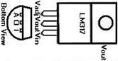 |
$0.75 |
| LM317L |
80V |
0.10A |
1.25Vadj |
100µA |
1.9ΔV |
Positive |
TO-92 |
125°C
5mAmin |
|
$0.58 |
| LM317xls |
Excel file |
|
Excel file |
Excel file |
|
Excel file |
Excel file |
Excel file |
| LP2950-33 |
30V |
0.10A |
3.30Vfixed |
100µA |
450ΔmV |
Positive |
TO-92 |
125°C
0.0mAmin |
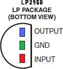 |
$0.49 |
| opamp |
-----2 | -----3 | -----4 |
-----5 | -----6 | -----7 |
8----- |
LM124A
LM224A
LM324A
"Junk Box Must Have" |
32V |
20mA |
3000µVos |
0.5mHz |
0.25V/µS |
Quad |
DIP-14 |
| LM358A |
32V |
20mA |
7000µVos |
0.5mHz |
0.25V/µS |
Dual |
DIP-8 |
| AD8639 |
16V |
19mA |
23µVos |
1.3mHz |
2.50V/µS |
Dual |
SOIC-8 |
| comparato |
-----2 | -----3 | -----4 |
-----5 | -----6 | -----7 |
8----- |
| LM339A |
36V |
6mA |
2mVos |
1.3µS |
300nS |
Quad |
DIP-14 |
| LM393A |
36V |
6mA |
5mVos |
1.3µS |
300nS |
Quad |
DIP-8 |
| tempsensor |
-----2 | -----3 | -----4 |
-----5 | -----6 | -----7 |
8----- |
| LM50BIM3X |
4.5V-10V |
130µA |
100mV@-40°C
1750mV@125°C |
+-2°C |
Analog |
SINGLE |
SOT-23 |
| diode |
-----2 | -----3 | -----4 |
-----5 | -----6 | -----7 |
8----- | -----9 |
1N4007
"Junk Box Must Have" |
1000V |
1.000A |
1.10V@1A |
3.00W |
175°C |
15pF@4V |
DO-201AD |
Silicon |
| 1N5404 |
400V |
3.000A |
1.00V@3A |
3.00W |
150°C |
50pF@4V |
DO-201AD |
Silicon |
1N4004
"Junk Box Must Have" |
400V |
1.000A |
1.10V@1A |
3.00W |
175°C |
15pF@4V |
DO-201AD |
Silicon |
| HSS82 |
200V |
0.125A |
1.00V@100mA |
0.40W |
200°C |
1.5pF@0V |
DO-34 tiny |
Silicon |
1N4148
"Junk Box Must Have" |
100V |
0.300A |
1.00V@10mA |
0.50W |
175°C |
4.0pF@0V |
DO-35 |
Silicon |
| PMBD7000 |
100V |
0.215A |
0.82V@10mA |
0.25W |
150°C |
1.5pF@0V |
Dual SOT-23
Comm Anode |
Silicon |
| BAW56 |
85V |
0.200A |
0.855V@10mA |
0.35W |
150°C |
2.0pF@0V |
Dual SOT-23
Comm Anode |
Silicon |
| 1N4454 |
75V |
0.400A |
1.00V@10mA |
0.50W |
175°C |
4.0pF@0V |
DO-35 |
Silicon |
| MMBD4148 |
75V |
0.200A |
1.00V@10mA |
0.35W |
150°C |
4.0pF@0V |
SOT-23 |
Silicon |
| BAS416 |
75V |
0.200A |
1.00V@10mA |
0.25W |
150°C |
2.0pF@0V |
SOD323 |
Silicon |
| 1N270 |
50V |
0.040A |
1.00V@200mA |
0.05W |
90°C |
0.8pF@1V |
DO-7 |
Germanium |
| SB540 |
40V |
5.000A |
0.55V@5A |
2.75W |
125°C |
500pF@4V |
DO-201AD |
Schottky |
| 1N5819 |
40V |
1.000A |
0.60V@1A
0.20V@10mA |
|
125°C |
110pF@4V |
DO-41 |
Schottky |
| RSX501L-20 |
20V |
5.000A |
0.39V@3A |
1.50W |
125°C |
1000pF@0V |
SOD-106 |
Schottky |
| G331 |
20V |
0.050A |
1.00V@5mA |
0.05W |
75°C |
1pF@1V |
DO-7 |
Germanium |
| zener |
-----2 | -----3 | -----4 |
-----5 | -----6 | -----7 |
8----- | -----9 |
| NZX2V1B |
2.1V@5mA |
200mA |
0.500W |
Δ100Ω |
175°C |
5% |
SOD27 |
Zener |
| BZX84C2V7LT1 |
2.7V@5mA |
83mA |
0.225W |
Δ100Ω |
150°C |
10% |
SOT-23 |
Zener |
| BZX79-C5V1 |
5.1V@5mA |
70mA |
0.40W |
Δ60Ω |
200°C |
5% |
DO-35 |
Zener |
| 1N4625 |
5.1V@5mA |
70mA |
0.40W |
1.5KΩ |
175°C |
5% |
DO-35 |
Zener |
| 1N4757 |
51V@250µA |
20mA |
1.00W |
1500Ω |
175°C |
5% |
DO-41 |
Zener |
| 1N4760 |
68V@250µA |
15mA |
1.00W |
2000Ω |
175°C |
5% |
DO-41 |
Zener |
| 2EZ91D5 |
91V@5.5mA |
20mA |
2.00W |
3000Ω |
150°C |
5% |
DO-41 |
Zener |
| 2EZ110D5 |
110V@4.5mA |
17mA |
2.00W |
4000Ω |
150°C |
5% |
DO-41 |
Zener |
chace
 The circuit board and sensor assembly of the Chace tracker.
The circuit is not water proof so a protective plastic dome is needed. I have used 2 liter clear plastic soda bottles. They last a long time, at least 5 years for one I have used, probably a lot more. This circuit will fit into the 20 Oz. size. The plastic bottle chosen needs to have a round bottom, the type that comes with the black plastic bottom which is removed. The type with the molded in feet don't work very well as they diffract the light too much.
Glass jars are even worse optically if looking through the bottom.
Any one out there with a good idea for a better weather dome?
In Minnesota I have snow that builds up on the top of the dome. This snow is quite reflective and can confuse the sensors as to the correct direction for the brightest portion of the sky when in the sky is overcast. It's easy to just brush the snow of but this is not always timely. I have experimented with putting black opaque paper inside the dome to eliminate the light from the snow. Another paper light blocker can be put under the sensors to stop the reflected light from the snow on the ground.
dome
 Dome on Chace tacker
This weather dome is made from a 2 liter pop bottle.
jiff
I have tried and like using 
plastic Jiff Peanut butter jars
dcb
DCB's implementation of the LED3 tracker with Pyrex Weather Dome.
This dome is made from an unusual deep style Petri dish.
doc
Doc's implementation of the LED3 tracker with a Fruit Jar Weather Dome.
Doc emailed this to me:
The power produced from the system is run to the main house. In the house, the 120 volt service is connected to its own fuse box to run all of my 120 volt stuff. The LED3 increased the output of the 4 panel array by 50%, as compared to the output of an identical 4 panel array mounted on the roof.
During mid-day, the power output of my system bulk charges the batteries and the C40 disconnects the solar panels to keep from over-charging the batteries. This never occurred before I installed the LED3. This is great!!
danbennet
Dan Bennet's Dish.
12 foot parabolic dish with 10,300 1" pieces of mirrors on it. It weighs around 1,200 lbs with the boiler .
wolfendale
Martin Wolfendale's implementation of the LED3 tracker with a machined plastic Weather Dome.
Martins PV panel mount is homemade and looks very nice. He is in Austrailia so things might seem a bit reversed to us northerners.
gary
Gary <gposavad@home.com> has suggested making the dome from Lexan. He wrote:
It's fairly easy to make a perfect dome out of Lexan.
Make a 2 piece mould out of whatever you can find that's the right size.
Heat up a piece of Lexan in your oven at about 200F for about 5 min.
Put it on the mould and press and release.
Trim off the excess after it cools.
If you want really good optics leave room in the mould for a piece of flannel on each side.
Scratches are polished out with toothpaste.
I Got this from EAA Sport Aviation to make nice wing tip strobe light covers.
mrea2001
Demo of my tracker at the 2001 Midwest Renewable Energy Fair
mrea2002
Demo of my trackers at the 2002 Midwest Renewable Energy Fair
mrea2003
Demo of my trackers at the 2003 Midwest Renewable Energy Fair
ledshex3
 LED3 Schematic
XOR Type Tracker
ledshex3layout
 Layout
ledshex3molex
 Molex Connector
The tracker consists of pairs of LED photo sensors. Each pair controls the voltage applied to one terminal of the actuator motor.
led3operation
When the easterly pair says go west the minus terminal is grounded. When the westerly pair says go west the positive terminal is connected to plus and we get westerly movement. Or vise versa for easterly movement
When they disagree then either both motor terminals are grounded or have plus on them, and we get no movement.
There are four operational states for the sensors to be in.
Each LED pair tends to move the tracker East or West.
An LED pair tends to move to the West or
An LED pair tends to move to the East.
Each of the LED pairs controls one side of the H-bridge.
| LED Pair 1-3 |
LED Pair 2-4 |
H-bridge Left |
H-bridge Right |
Movement |
|
| West |
West |
Low |
High |
Move West |
| West |
East |
Low |
Low |
Stopped |
| East |
West |
High |
High |
Stopped |
| East |
East |
High |
Low |
Move East |
Note! Unlike most H-Bridge drivers where both sides are always driving the load this circuit has independent drives for each side. This allows the motor to stop when both sides are high or low. The motor moves when they are different.
In addition, both sides have the top MOSFETs turned off most of the time until the clock enables movement by periodically pulling R9 and R11 low.
Q3 and Q4 form a gated level shifter. To see how this driver works think of the bottom end of R9 and R11 being grounded when the top transistor is to be enabled.
Also the driver for the left side are inverted from the driver on the right side. This is a method for returning the tracker to the east, for parking, if R2 and R3 are used. This way Q1A will be enabled and Q2B will be on when in the dark.
parking
In cloudy or overcast weather the tracker seeks the brightest part of the sky. At night it moves to the easterly parking position. The parking position puts the panel at a steep angle so night time snow doesn't accumulate as much in the winter. A westerly parking position is obtained by mounting the tracker upside down and reversing the leads to the actuator motor.
led3x
LED3X LED Sensor Electronic Tracker with H-Bridge Drive.
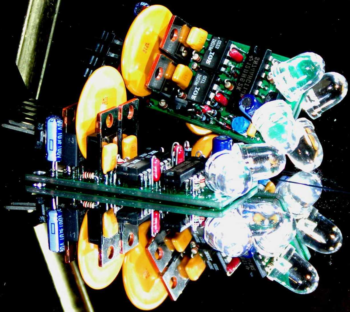
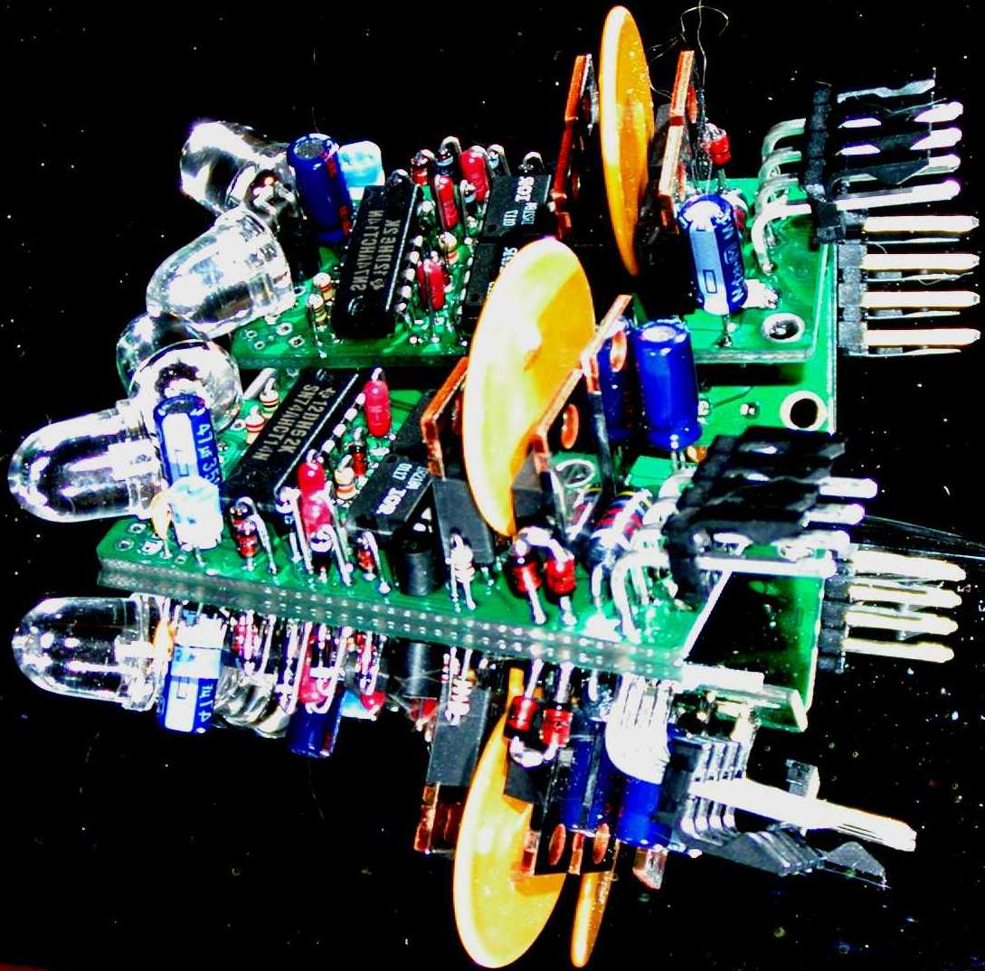
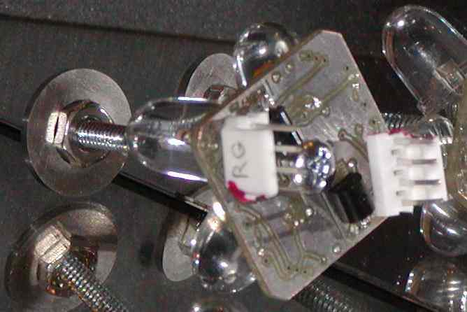
LED3X Solar Tracker
The LED3 using surface technics was just to hard to assemble in a timly manor as sales were increasing. I needed a circuit that could be built with mostly through hole components. At the same time, there were other features and enhansments that I thought were needed. This was the impetus for the LED3X series of solar trackers.
This circuit uses power MOSFET drivers and is designed to operate satellite dish linear actuators, however most any DC motor can be used. The power drivers are capable of delivering about 50 amps of peak current, maybe more. When better transistors become available this current can be increased. The large power MOSFETS, 72A, when operated at low duty cycle or low currents eliminates the needed for a heat sink on the transistors. Neat huh!
The duty cycle is adjustable from 0% to nearly 100%. Idealy tracking from stop to stop should be 10 to 30 minutes. The duty cycle helps to slow down the motor drive speed. Less duty cycle will make the tracking slower but, we don't need speed anyway. Slow tracking speed helps in partly cloudy condition. This prevents the tracker from making unnecessary movements when clouds move by.
led3xshadow
To improve accuracy, ie. with concentrators such as troughs or dishes, a shadow blocker can be placed in front. Similar to the shadow blocker on the Chace Tracker or like this:
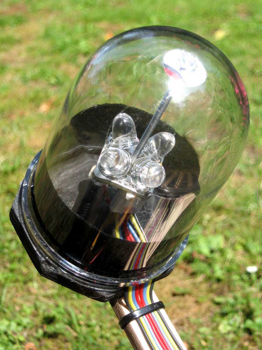
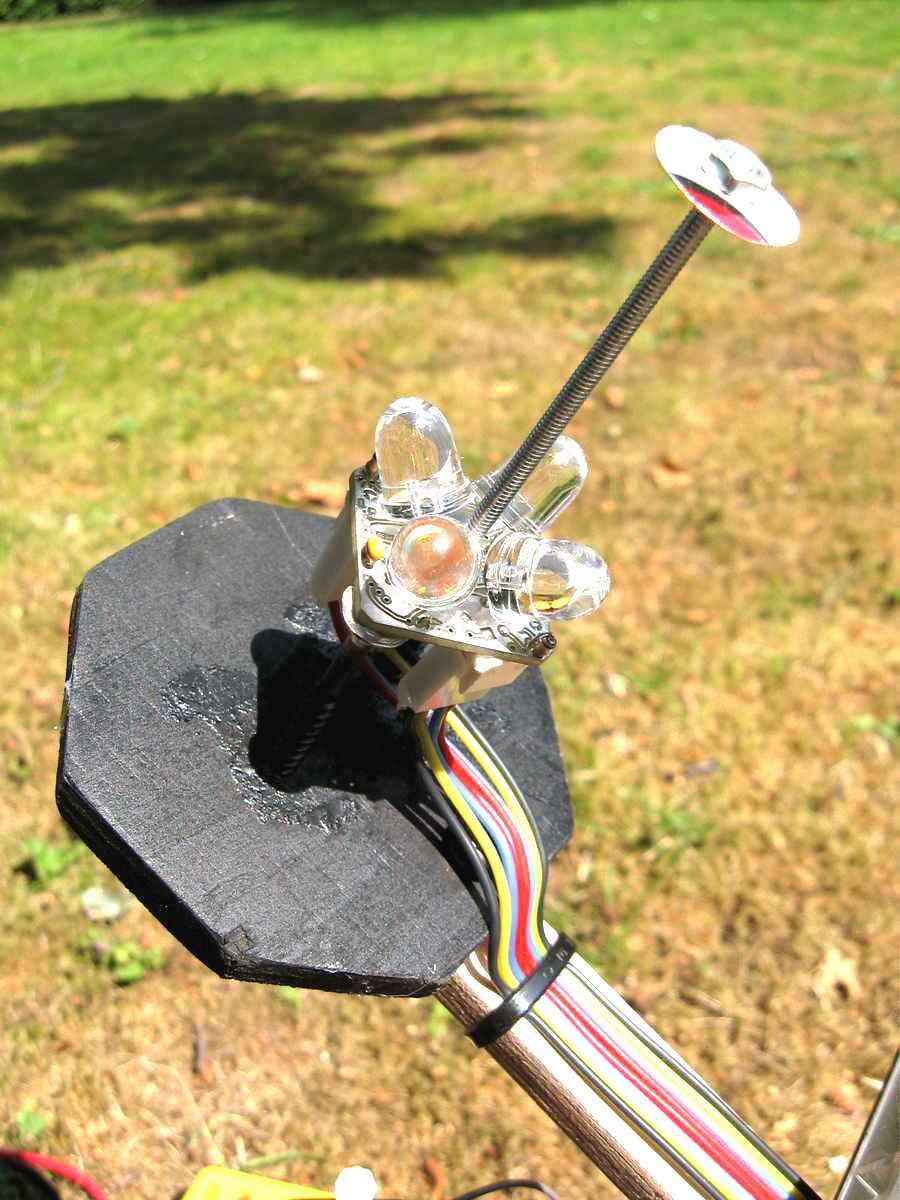
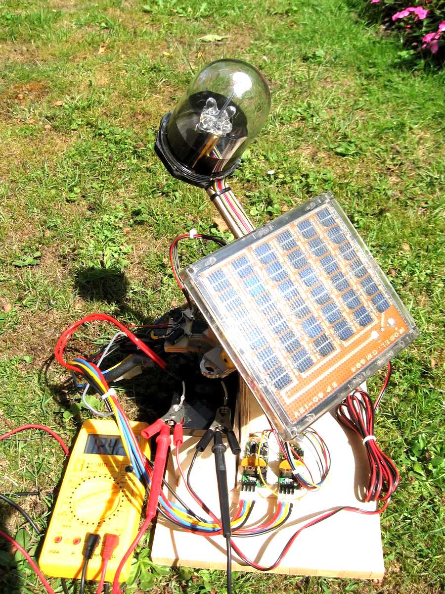
OK, this is an example of a dual axis version.
The single axis version uses a strip of metal.
Cool weather dome!! As I recall the dome is polycarbonate and from the oil or water traps on air lines and regulators.
I have used a band of metal about .5" in width at about 2" from the LED3X sensor. If the LED3X is used for E-W tracking the band is oriented N-S. Conversely, if the LED3X is used for N-S tracking the band is oriented E-W. The shadow device is not particularly critical. For instance, I have used black electrical tape on the weather dome and it worked well.
led3xremotesensor
LED3X Remote Sensor
The remote sensor comes can be configured in several flavors.
1. Single axis
2. Dual axis
And parking or no-parking on either axes.
The PC board is configured in 2 halves. Each half is an individual single axis sensor. For single axis use the board is cut in half or dual axis if left whole. Depending on which components, positions, and jumpers installed all the configurations can be obtained.
led3xremotesensorschematic
Dual Remote Sensor Schematic
led3xs24vspecifications
LED3X Specifications
For a more detailed set of specifications, options, and pictures see the web page devoted to assembling the kit. And a lot more pictures and application information.
| Power Supply Voltage | 10.5 Volts to an absolute maximum of 44 Volts inclusive.
The 10.5V minimum is specified as the under voltage point. Less voltage protects the power mosfet in the H-bridge driver circuitry.
The 44 volt maximum is defined by the voltage tolerance of the 51V protection zener. This zener protects the power MOSFETs from seeing damaging breakdown voltages.
The 51V zener has an initial tolerance of 5%. So the maximum continuous voltage that can be applied before conduction can occur is 48V or so.
Most PV panels don't output more than 44V in open circuit. You should check for sure. If they do go too high in voltage a simple power regulator should be added to limit the maximum voltage.
|
| Load Current Continuous | 9 Amp resistive.
The power MOSFETs are rated at over 70A at 25°F. A conservative derating of 50% is prudent especially in hot weather conditions.
|
| Load Current Intermitant | 20 Amp intermitant at 1S width once per timing cycle of 60S.
The Power MOSFETs have an absolute maximum current rating of 72A, but this is with ideal conditions where the temperature is 25°F and very fast gate rise times. The LED3x has a relatively slow gate rise time and may be operated at quite high temperatures due to the weather. I think 20A at about 1S is adequate for normal tracking applications.
If higher current motors are required a power amplifier may be needed. See:
http://www.redrok.com/electron.htm#power
I should note that the satellite dish actuator I use normally consumes about 290mA of current at 13.8VDC. This actuator is capable of driving a 15' dish with 1500lb of force. You don't need a high powered drive, just a slow forceful one.
Think slow!
|
| Operating Temperature | -40°F to 185°F or -40°C to 85°C
|
led3xforsale


LED3XS24Vc3 For Sale
Please go to this page:
http://www.redrok.com/led3xassm.htm#led3xforsale
power
Some have expressed an interest in driving high powered loads beyond the capabilities of the H-Bridge driver transistors. To this end I developed several high powered driver circuits, (actually their almost the same circuit as in the relay trackers).
relaydc1
 RelayDC1
Relay circuit that uses DC relays with 12VDC coils. The DC motor in this case is a permanent magnet type that is reversible.
relayac1
 RelayAC1
Relay circuit that uses AC relays with 12VDC coils. The AC motor in this case is a capacitor run type.
relayac2
 RelayAC2
Relay circuit that uses AC Solid State relays with 3 to 32 VDC control inputs. The AC motor in this case is a capacitor run type.
manualops
led3manual
led3xmanual
 LED3XManual
Some have expressed an interest in adding a switch to manually move the array for test purposes. One of these circuits, when added between the tracker and actuator, will allow manual movement. The first circuit has a fast and slow position. The second circuit is slow only but simpler. The first circuit is the nicest.
Since I do the assembling variations can be easily made for such things as a change in the timing of the oscillator for other duty cycles or to disable the parking feature. I am currently selling the assembled units without the parking feature.
assemblyled3x
 Assembly & Opperating Instructions for the LED3X series. Plus a lot of pictures and examples.
led3xenergy
The circuit draws about 15mA when idling. It can operate at temperatures to -40F or up to 158F. Its designed to operate from a 12V or 24V lead acid power source. I generally recommend using a 36V actuator on 12V.
The daily energy consumed is quite small. My actuator draws about 290mA and can go from stop to stop and back in about 5 minutes. So:
((.015A * 24hr/day) + (.290A * 5min/day / 60min/hr)) * 13.8V = 5.3Whr/day
Or about 5Whr/day, which is pretty small.
trickle
A very small 5W or even a 2W PV panel and small wet cell lead acid battery is a good combination for the power source to run the system. Wet cell manufacturers say you can "trickle charge" them continuously at 1% to 2% of the amp hour capacity. A trickle charger has no voltage regulation.
A 12V 5W panel can deliver about 400mA of current. So the smallest lead acid battery can be about 20Ahr of capacity.
A 12V 2W panel can deliver about 170mA of current. So the smallest lead acid battery can be about 8Ahr of capacity.
Periodically these batteries need to be watered with distilled water.
Note! I used to say it was OK to use gel cell lead acid batteries. This was a mistake on my part. Trickle charging by definition is over charging and gel cells are damaged when over charged wet cells are not.
While trickle chargers are simple it is often better to use a small solar charge controller such as the Morningstar SunGuard SG-4 or others. Make sure you select one that has Temperature compensation. This solution will greatly reduce the watering requirements of wet cell batteries or use of gel cells.
I intend that this circuit will supplant the Chace tracker as its simpler to build and adjust.
For two axis tracking two circuits are needed. However, for PV panels the second axis only adds about 5% on the average and may not warrant the added expense.
economics
Many have said that it makes no sense to use a solar tracker with PV systems as it is cheaper to just add an extra panel for every three. To this I say bunk.
Using the NREL data:
My link.
http://rredc.nrel.gov/solar/pubs/redbook/redbook_index.html
I find that in Minnesota a single axis tracking PV panel will have a 40% increase in output in December and a 100% increase in June.
In Minnesota:
A PV panel with 15% efficiency
in December tilted to your latitude plus 15°s.
http://rredc.nrel.gov/solar/old_data/nsrdb/redbook/atlas/
2 to 3 kWhr/m2/day lets say 2.5 solar
2.5 kWhr/m2/day * 15% = .375kWhr/m2/day electric
Or a single axis north-south tracking panel at lat. +15°.
3 to 4 kWh/m2/day lets say 3.5 solar
3.5 kWhr/m2/day * 15% = .525kWhr/m2/day electric
.525 / .375 = 140%
This shows 40% improvement with a tracker in December.
Lets do it in June:
4 to 5 kWhr/m2/day lets say 4.5 solar
4.5 kWhr/m2/day * 15% = .675kWhr/m22/day electric
Or a single axis north-south tracking panel at lat. -15°.
8 to 10 kWhr/m2/day lets say 9 solar
9 kWhr/m2/day * 15% = 1.35kWhr/m2/day electric
That's a 100% improvement with a tracker in June.
Of course your location will have different results. For instance I just did it for San Jose, CA and got an increase of only 14% in both June and December. Clearly this is not the best place to do solar tracking.
Here are the 4 maps that I used.
nrelmaps
 Click the map!
The full set of maps from NREL are here.
I don't have a cost for the tracking mount but the actuator I'm using costs about $140us and my tracker is $35us. PV panels now are about $5us/W so a 100 watt panel costs $500us. Using a system of 3 panels this is $1500us.
Since the tracker delivers at least 40% more output, in December, it would be fair to say that the tracker has an equivalent value of $600us in a 3 panel 300W system. I can't see the tracking mount would cost $600-$140-$35=$425 more than the equivalent stationary mount that has to hold at least 4 PV panels. Of course, the comparison is even better in June with the 100% increase.
Today there are many obsolete C-band satellite dishes. These have polar axis mounts which are almost ideal for use with arrays of PV panels. Remove the dish and install racks to support the panels. They are well designed and very strong. They have all the needed hardware including the motor actuator. Besides they are often free for the asking.
tripod
2pivot
2pt
Tripod Mounts
2 Pivot Tripod Mounts
The basic Tripod Mount, essentially, has 2 pivot points.
Usually, one pivot is higher than the other by an angle, roughly, the same as the local LATitude.
There are variations of these I call a "3 Pivot Tripod" and another I call a "4 Pivot Horizontal Axis" mount.
Tripod Tracking Mounts, (2 Pivot Tripod type), are stronger in every way compared to Polar Axis Tracking mounts perched on top of a post. Stronger means the system is lighter and lower cost to construct for similar strength ratings.
I'm convinced that the best and strongest mount concept for PVs at ground level is one based on the design examples of Vladislav Poulek.
poulek
traxle
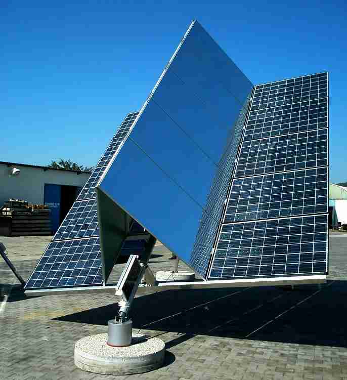
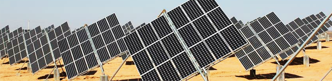
* Traxle
Poulek Solar
by Vladislav Poulek
Gary A. Werner, President GWM Corporation
Polar mount with tracker.
The tripod support arrangement is very strong with light weight construction.
The second image, above, has mirrors to increase the concentration to 1.5X.
While I doubt Poulek actually is the first to make this mount type, he does have a patent, US6089224, on this concept.
aps
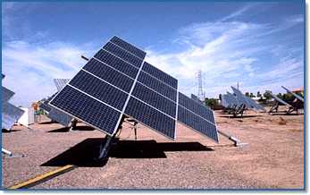 * APS Solar's Pseudo Polar Axis "Tilt Tracker".
Similar to Poulek Solar's Traxle, with a clockwork tracker. The second axis, the tilt axis, is adjustable for a few percent improvement in total output. The actuators are hydraulic.
powerlight
 PowerLight
An even bigger version, similar to Poulek Solar's Traxle.
sunpower
nellis
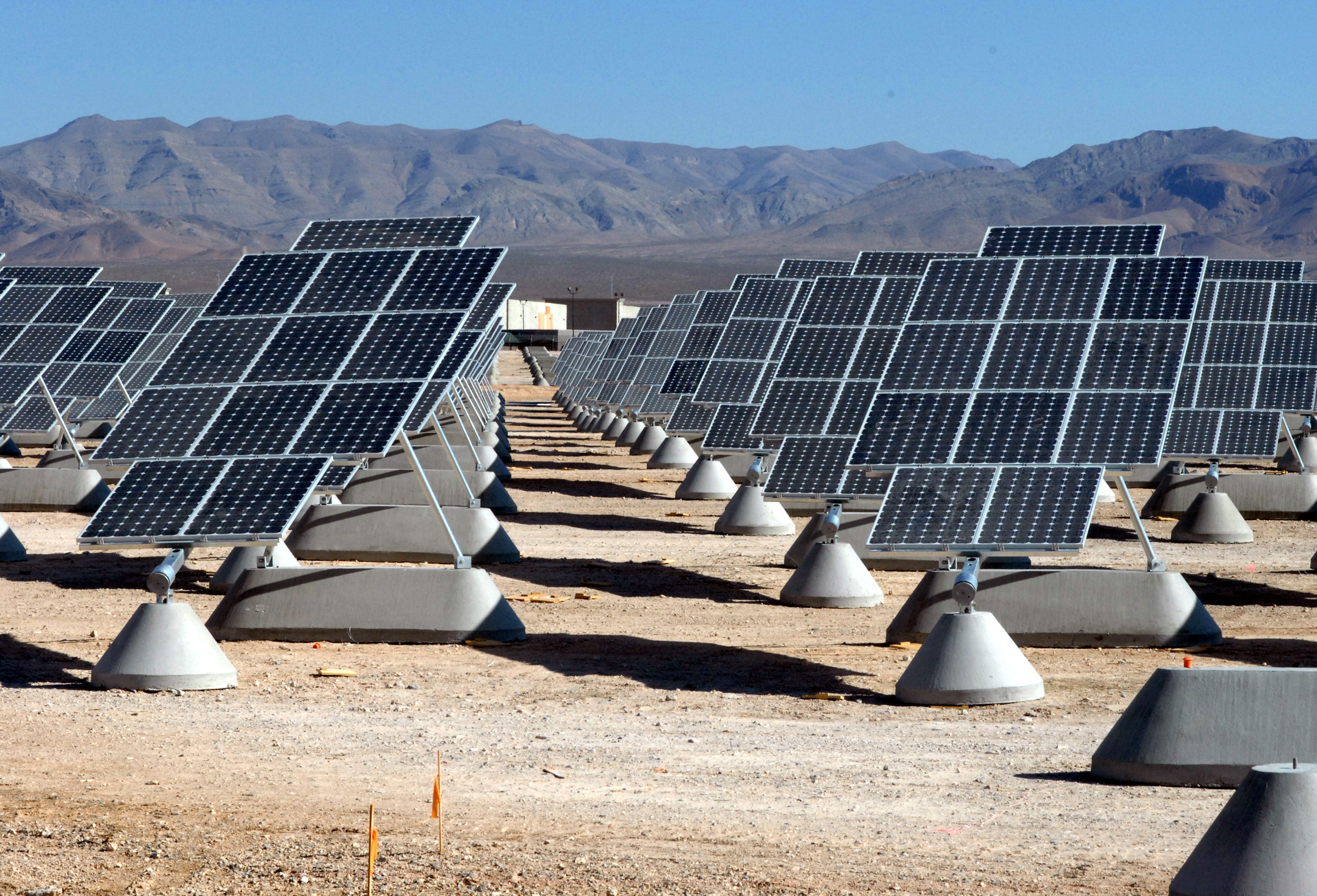 * SunPower
A huge field of Polar Axis Tripod Solar Tracking Mounts at Nellis Air Force Base.
36.258376,-115.052763
(SunPower purchased PowerLight.)
It should be noted that they were required to use those large concrete blocks because they are not allowed to drill holes in the restricted Mohave Desert. Go figure!
energyoptions
Energy Options PV Polar Axis Tripod Mount
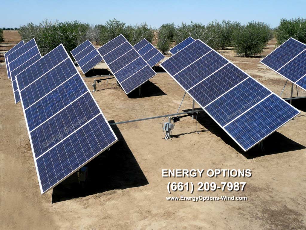
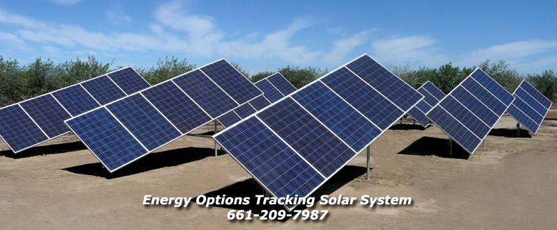
* Energy Options has this very nice tripod mount for sale that uses a single axis tracker. The main leg is angled up from horizontal at the sites LATitude of about 35°.
OK, not actually a tripod as the north end is a vertical pole but the concept is the same. The tracker used in this case is an LED3XS24Vc3RIP with the reverse inhibit feature.
This example has a link between several mounts with a linear actuator moving the set. Very cool!
gordon
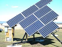
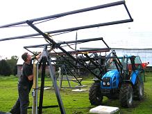
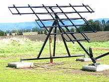
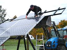

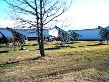
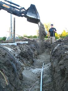
Glen Gordon's Pseudo Polar Axis Tripod Mounts.
He has 7 of these, WOW!!! They are VERY nicely done. They look very strong compared to mounting on top of a post.
He is tracking each of them with an LED3XS24Vc3P and driving each 24V C-Band linear actuator from 12V to slow them down.
Seasonal adjustment of the Pseudo Polar axis is accomplished by changing the high end mounting height.
His Latitude is about 45°.
mecasolar
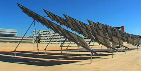 * MecaSolar
Nice Polar Axis Tripod Mounts.
Arrays of mounts.
Video of MecaSolar in Action.
mecascrew
 MecaSolar's MecaScrew earth screw.
These screws are not useful for conventional post type mounts which must resist bending loads but are ideal for tripod mounts which must mainly resist tension/compression loads.
Video of MecaScrew Installation.
szymanski
szy
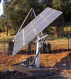
* Martin Szymanski's variation of a Pseudo Polar Axis Tripod Mount.
tinker
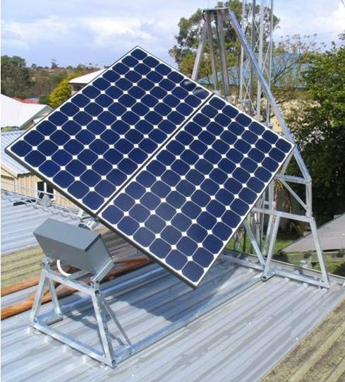 Klaus' variation of a Pseudo Polar Dual Axis Tripod Mount.
For more info see the forum entry at The Back Shed.
This is a Timer Based tracker. It basically advances 15° per hour.
luke
Joseph Luke's PV Polar Axis Bipod Mount
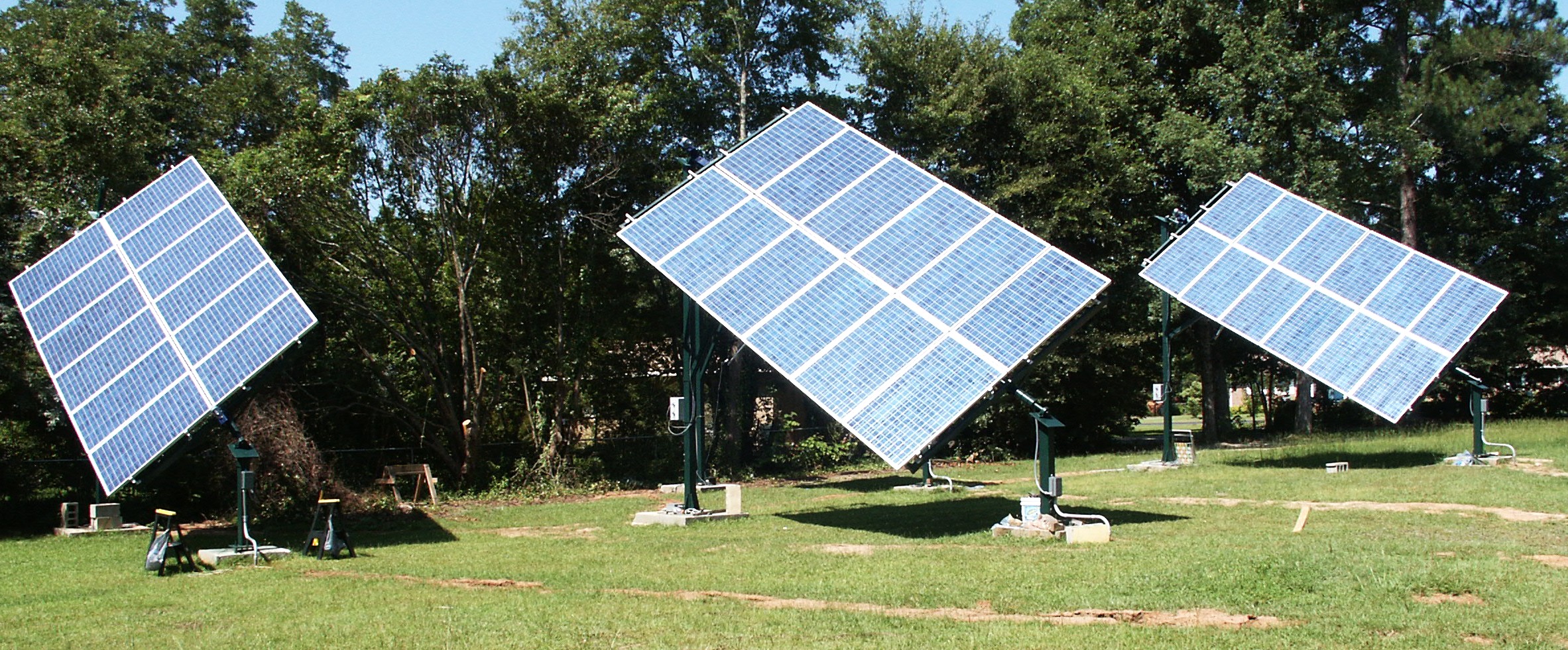
Joseph built this very nice tripod mount that uses a single axis tracker. The main leg is angled up from horizontal, on the North, by the sites LATitude.
OK, not actually a tripod, but is a Bipod, as the north end is a vertical pole but the concept is the same. The tracker used in this case is an LED3XS24Vc3RIP with the Reverse Inhibit feature.
javier
Javier Aguirre's PV Polar Axis Bipod Mount
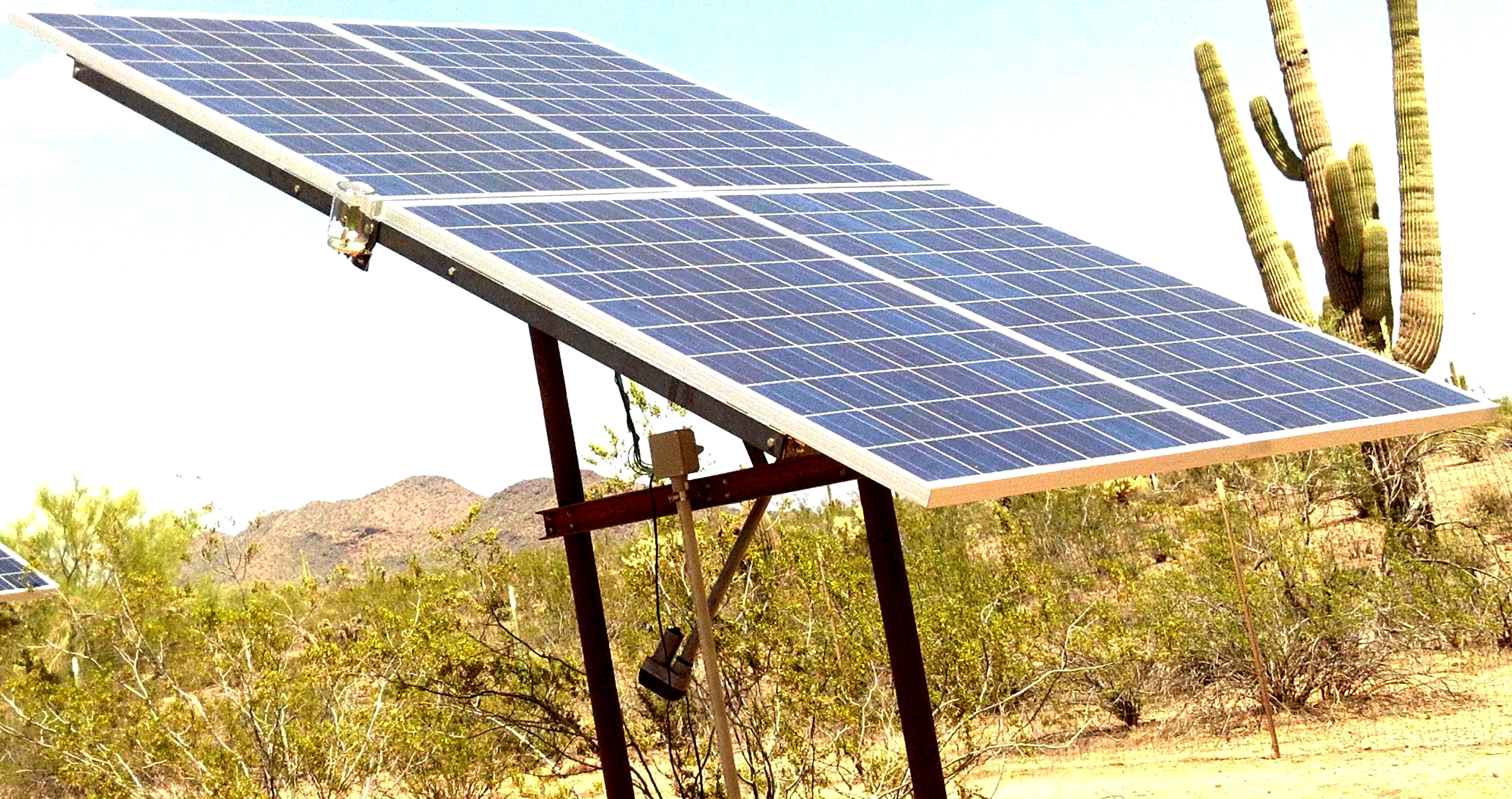
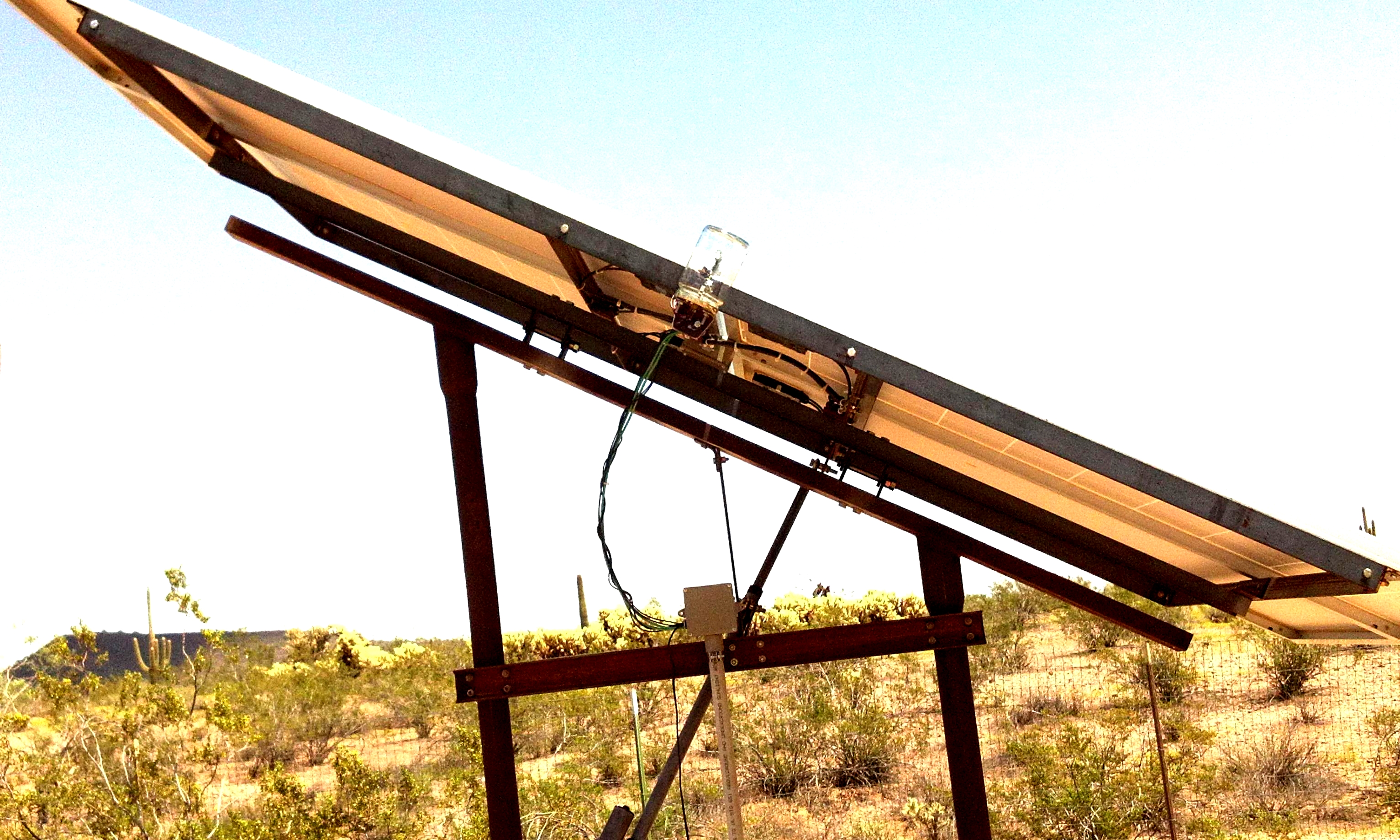
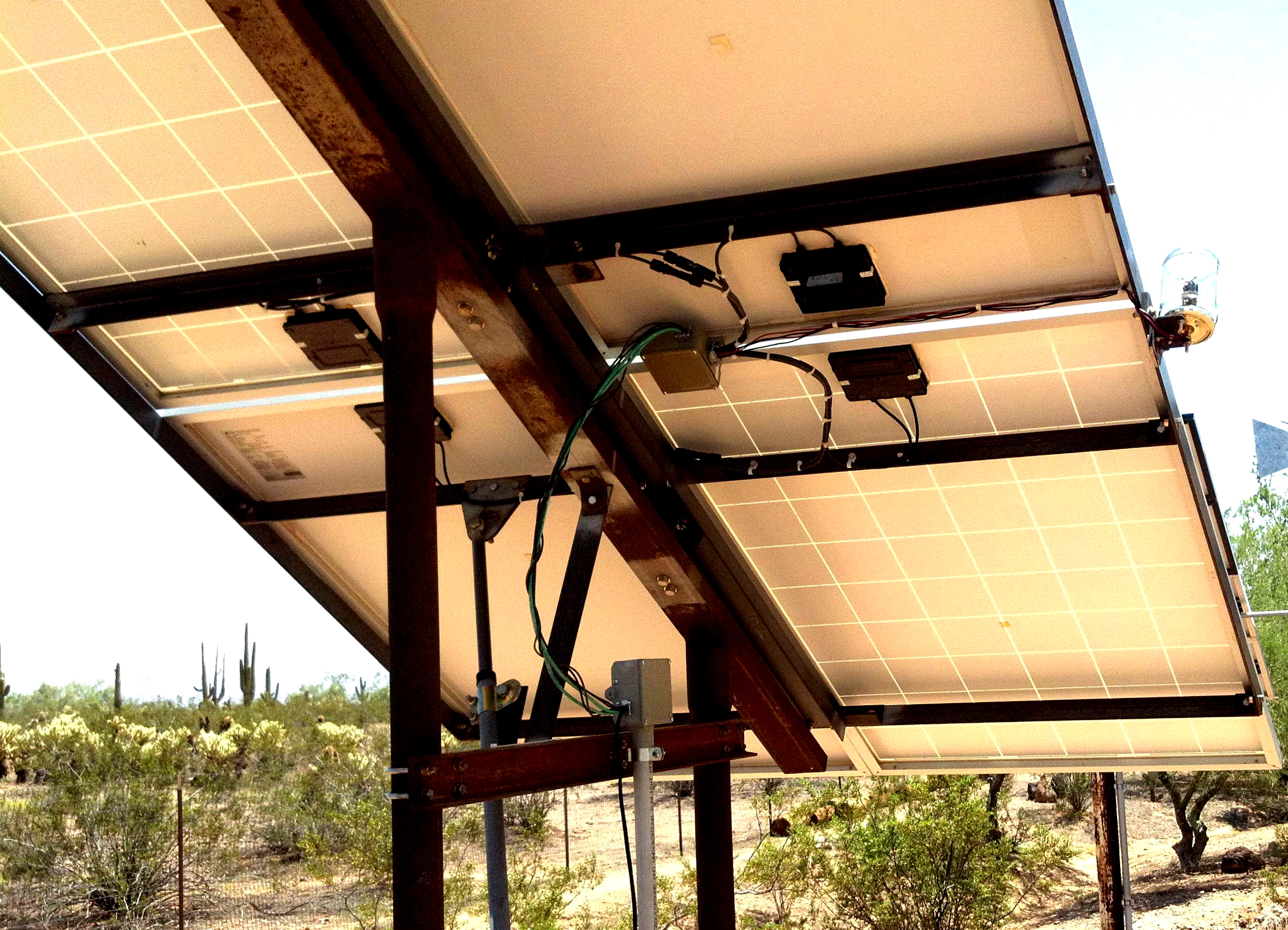
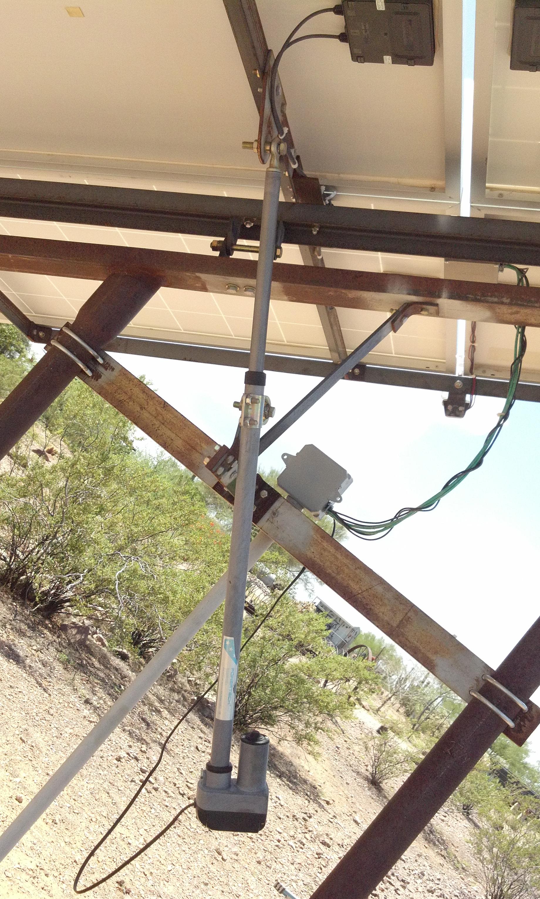
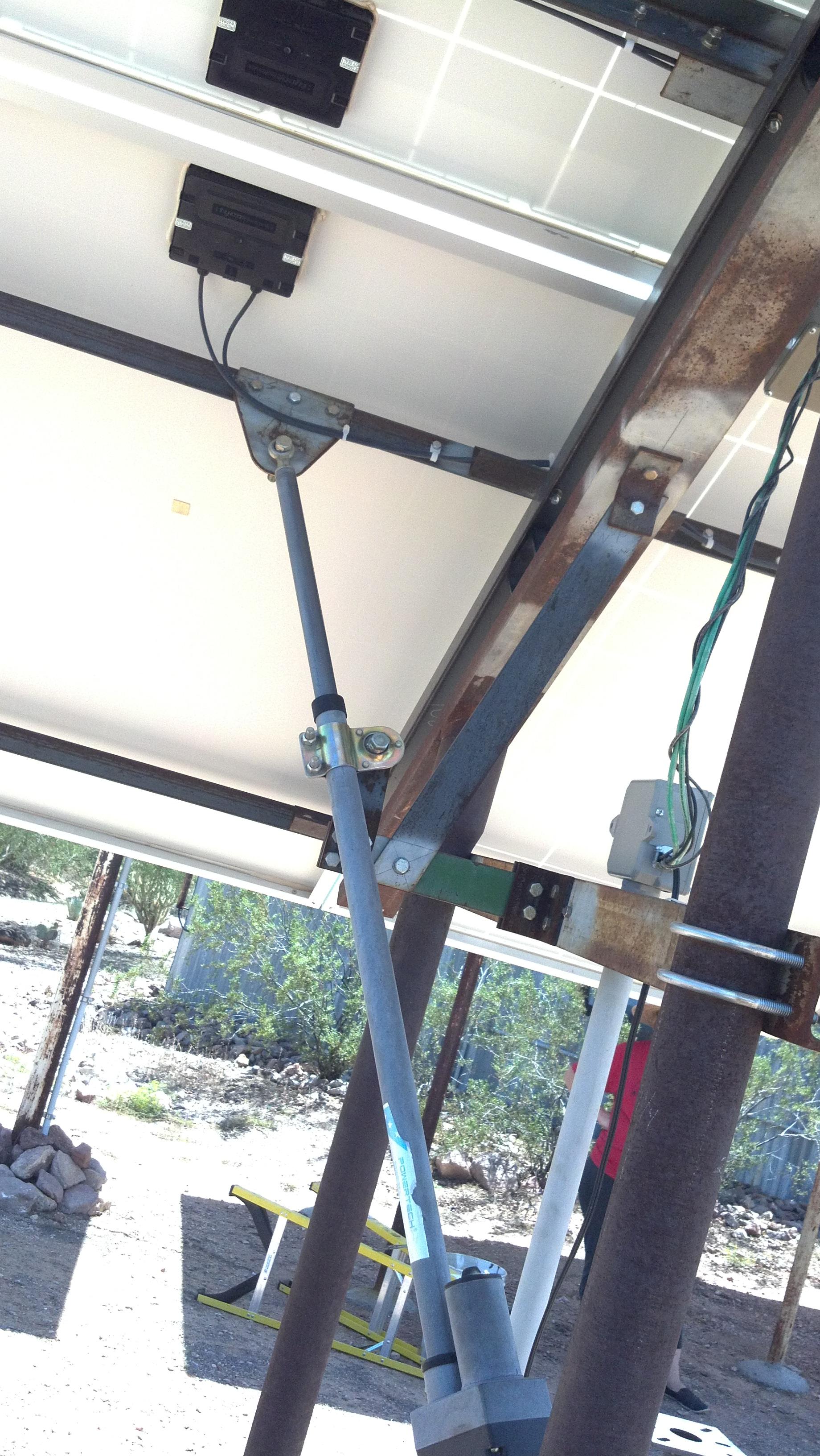
<Javier> built this very nice tripod mount that uses a single axis tracker. The main leg is angled up from horizontal, on the North end, by the sites LATitude of about 34° in Arizona.
The vertical legs are made from very heavy drill stem.
OK, not actually a tripod as the north end is a vertical pole but the concept is the same.
The tracker used in this case is an LED3XS24Vc3RIP with the Reverse Inhibit feature.
<Javier> said he would be willing to help if anyone had questions regarding construction of a similar system.
davis
Mike Davis' Single Polar Axis Tripod Mount
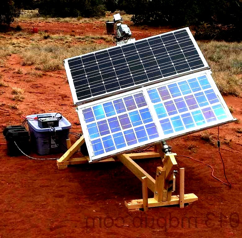
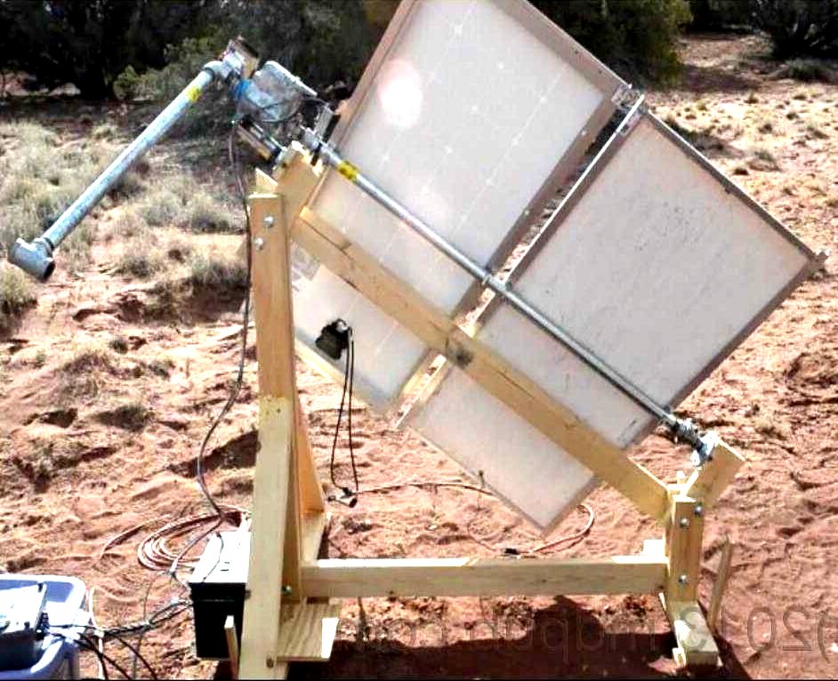
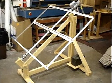
Mike built this nice tripod mount that uses a single axis tracker based on an Alliance "Tenna Rotor U-100". I Love these TV antenna rotators. They are extremely durable, with the main axis pipe passing strait through the body, they have a fairly high gear ratio, and a strong worm gear final.
However, the motor is difficult to drive with a normal solar tracker as the motor is a 24VAC capacitor run type. Mike used an ARM Cortex®-M-based MCU microcontroller to do it. For assistance see Welcome to Mike's World website. <Mike Davis>
Notice the nice pipe weight on the high end to counter balance the offset weight of the panels.
I would suggest using Solid State Relays to greatly increase the lifetime over the mechanical relays.
Mike was having problems with accurate tracking because he is sensing the open circuit voltages of the pair of small PV panels. The problem is PV cells open circuit voltage is relatively insensitive to light intensity. PV cells are actually "Current Sources" where the current is directly proportional to the applied light intensity.
One solution is to load the PV cells with a resistance which pulls the voltage down from the open circuit voltage, maybe 1/2 the open circuit voltage, with full intensity.
A better solution is to connect the PC cells "Anti-Parallel" so they are basically "Fighting" each other. This has an aiming accuracy better than 1/2° of resolution or better. This is what is done in my tracker which use LEDs as the sensors. It's also what is done with the model trackers that use a tiny motor for the movement.
Mike did improve the operation by adding an "Occulting Bar", (yes he is an astronomer), or what I would call a "Shadow Blocker". This increases the aiming accuracy.
However, if the PV cells were connected "Anti-Parallel" it would GREATLY increases the aiming accuracy.
In general, "Shadow Blockers" are not required for ordinary PV Panel tracking, there used mostly for concentrator systems where high accuracy is needed.
hill
Dave Hill's Dual PV Polar Axis Tripod Mount
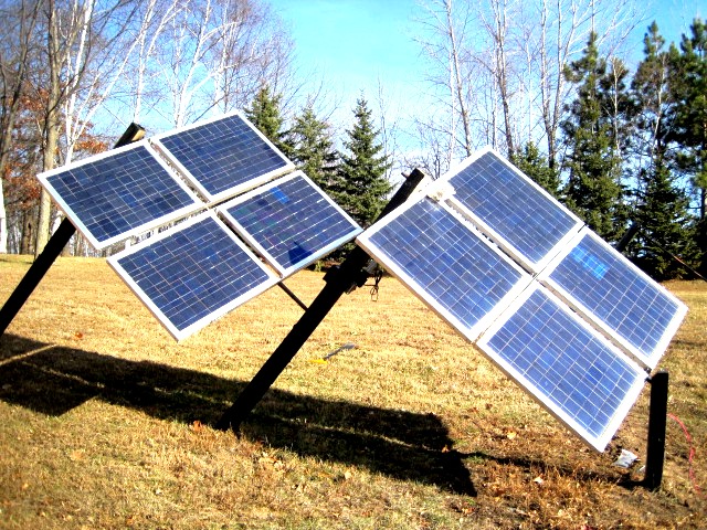
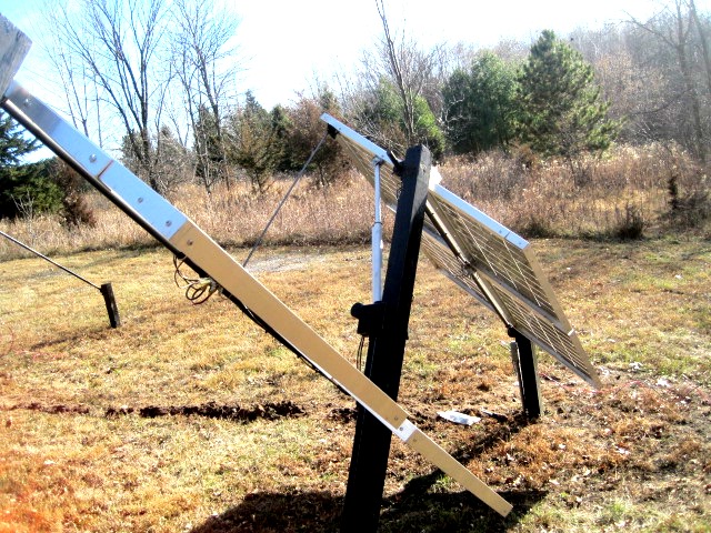
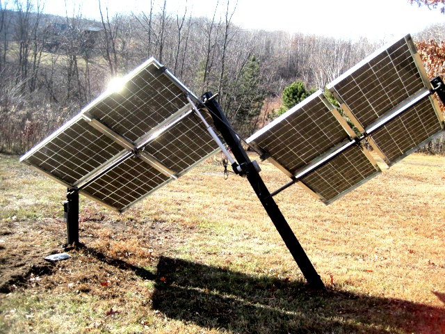
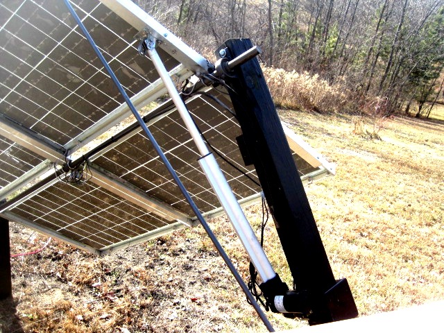
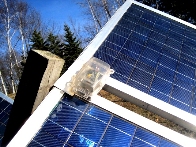
Dave built this very nice dual tripod mount that uses a single axis tracker with a second mount linked to the first. It looks to me more could be linked together, The main leg is angled up from horizontal at the sites LATitude.
OK, another mount one leg short of a tripod.
I've been thinking about shadowing problems and it appears that when the Sun on the Winter solstice half of the year, (northern hemisphere), the southern panel will shadow the northern panel. To alleviate the problem the two mounts need to have more spacing.
For assistance see "Shadowing Calculations".
The tracker used in this case is an LED3XS24Vc3P in a nice domed plastic electrical box.
brown
Robert Brown's Tripod Polar Axis Tracking Mount
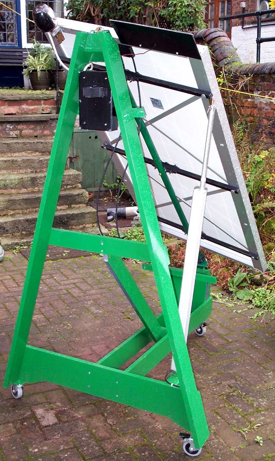
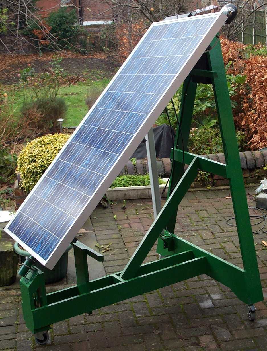
Robert Brown lives in the UK. That's why the angle is so steep.
His mount is loosly based on the polar axis designs of Martin Poulek's Traxle Tripod mounts.
pearson
Walter Pearson's Pseudo Polar Axis Tripod Mount
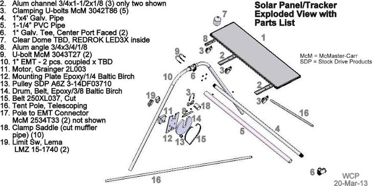
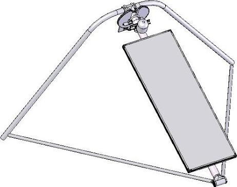
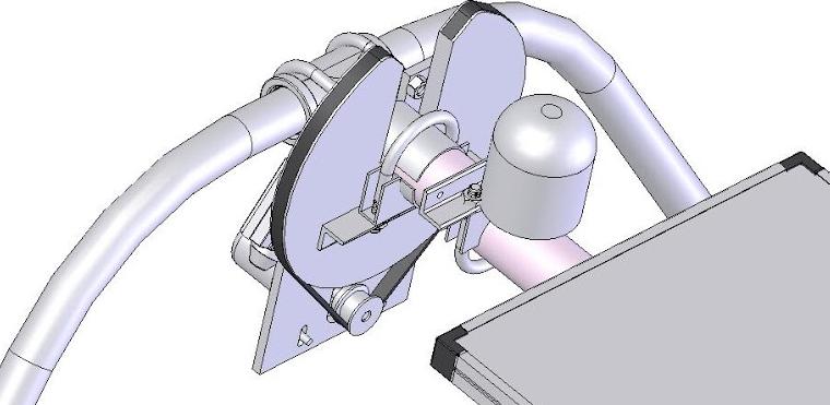
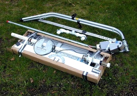
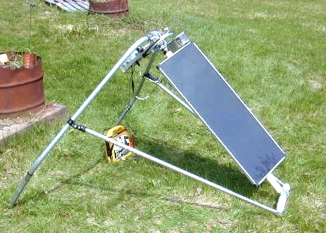
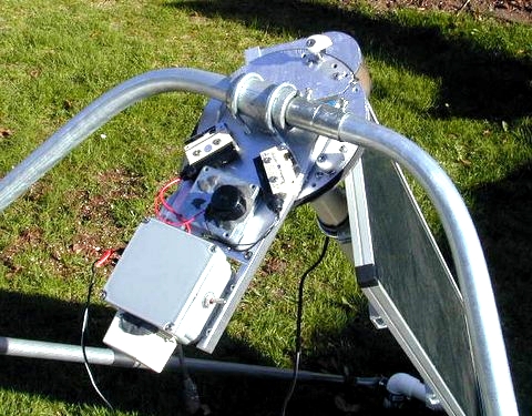
Walter built this very nice tripod mount.
Hey, one of my neighbors in St. Paul, MN.
It's "Pseudo" Polar axis because seasonal adjustments are made by adjusting the "Polar" axis away from the celestial pole.
He has given us a full parts list. Way to go Walter!!!
I very much like the "Rotary Motion" drive. This is way better than the use of linear actuators.
The Grainger 2L003 motor, 7189/1, and the 8/1 final gear ratio give a total gear ratio
of 57512/1 and a speed of about 8 minutes from end to end.
He is using the standard LED3XS24Vc3P solar tracker running on 12V.
This looks like it can be made quite portable when broken down.
See Walter's Differential Temperature Controller.
declinator
Z-Bar
"Z-Bar" Type DEClinator for Polar Axis Mounts
An interesting method to introduce +23.45° to -23.45° DEClination (pronounced [dekle·na·SHen]) adjustments for the seasonal motions of the sun.
See the US Patent US4011854.
OK, the patent describes the use of a "Z-Bar" Type, (Z shaped Z-bar), DEClinator on a dish but it works equally well with any direct tracked device such as PV Panels, Thermal Panels, or Troughs.
I usually suggest that DEClination doesn't need to be actively tracked.
Instead, just set it manually 4 times per year. Basically Spring and Fall Equinox +- 1 month.
(About March 1st, May 1st, September 1st, and November 1st. Which is close enough.)
Note! The DEClinator angle for 4 times per year manual adjustments would be 12° and set to angular positions from 0° to 360°.
| February 20th set DEClinator to |
0° |
for a DEClination of |
0° |
for 2 months |
| April 20th set DEClinator to |
90° |
for a DEClination of |
+12° |
for 4 months |
| August 22st set DEClinator to |
180° |
for a DEClination of |
0° |
for 2 months |
| October 22st set DEClinator to |
270° |
for a DEClination of |
-12° |
for 4 months |
| And back around |
| February 20th set DEClinator to |
360° |
for a DEClination of |
0° |
for 2 months |
Active DEClination tracking in a true polar axis mount can gain about 7% more energy per year over a fixed true polar axis mount at 0° of DEClination.
Four times per year manual DEClination adjustments gain about 5% of those 7%, i.e. just about 2% less gain in energy per year than actively tracking DEClination.
The great majority of energy gained per year over fixed panel mounts is in tracking Right ASCension.
This technique can be used with a vertical axis mount. I don't think this will work well as the angles can get out of hand, especially as you get closer to the equator, but it's theoretically possible. With these less than optimum orientations the DEClinator angles will always be more than with the ideal polar axis mounts at +-23.45°.
Even though not ideal I can see using this in locations such as roofs that don't have angles conducive to polar axis angles.
tripodmodel
Model Tripod with "Z-Bar" Type DEClinator
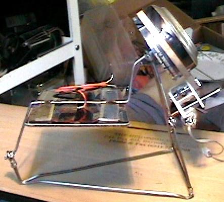
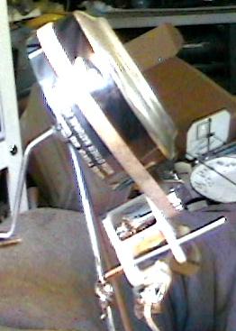
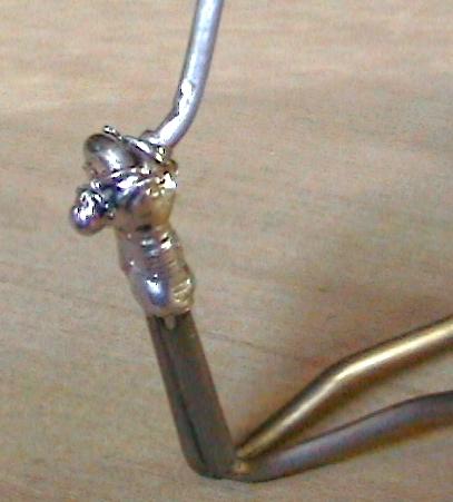
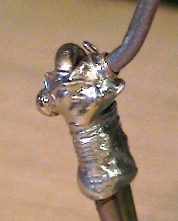
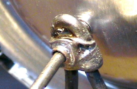
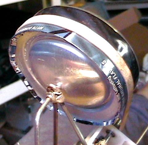
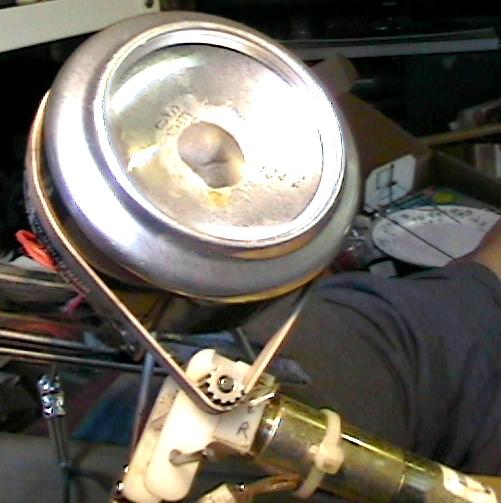

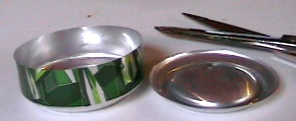
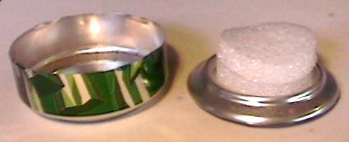
http://www.redrok.com/images/TriModSummerSolstice.AVI
http://www.redrok.com/images/TriModSEquinox.AVI
http://www.redrok.com/images/TriModWinterSolstice.AVI
http://www.redrok.com/images/TriModDEClinator.AVI
deformable z-bar
D-Bar
"Deformable Z-Bar" or "D-Bar" Type DEClinator
There is an alternative Declinator mechanism. The one above has the panels rotating about the Z-Bar. This one changes the shape of the Z-Bar.
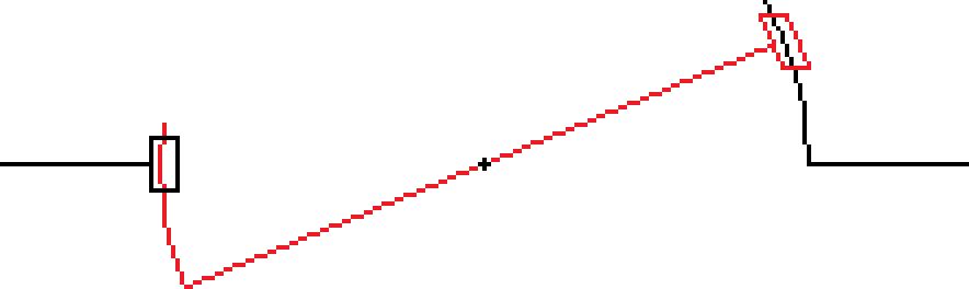
Note, the sliding mechanisms that allow the center section to change the angular relationship with the ends.
I thought about this quite a while back but didn't describe this before because it seams a bit complicated and weak. I guess I needed to describe it just to be complete.
tripodcalcs

* Here is an "Excel" spreadsheet to do the Tripod Calculations.
*http://www.redrok.com/TripodCalcs.xlsx
Note! These calculations ignore such things as Material Dimensions and Clearances, its essentially a stick figure. The values, as downloaded, are, roughly, for the coat hanger model with a 23.439° "Declinator Angle". I don't specify the units as the linear values are dimensionless, use any you like.
Many of the examples shown above have PV panels arranged in a "Triangular" or "Trapezoidal" pattern. This is done primarily to reduce the height of the structure without the panels hitting the ground or snow. A "Rectangular" pattern, can be used but the supports will be higher.
Most PV panels are rectangular. One should arrange these panels so the width is narrower at the low end and wider at the high end. To do this efficiently plot a circumscribed triangle around them and truncate the triangle on the lower end into an "Isosceles Trapezoid", a triangle with one point cut off. Also small triangles are trimmed from the trapezoid on the high end.
Enter:
1. The "Base" of the trapezoid as "Panel Width High End".
2. The "Top" of the trapezoid as "Panel Width Low End".
3. The "Height" of the trapezoid as "Panel Length".
I show some examples on sheet 2.
Adjust the "Green Entries" for your application. The main reason I had for writing this was to watch out for clearances from the ground, snow in my case, or the supports.
A second objective is to get a good estimate of wind loads and wind induced torques.
I'm making a couple of assumptions.
1. The wind force is applied evenly to the trapezoidal shape, (ignoring wind speed increasing with height). The actual forces on rectangular panels would be a bit less as they would have less total area than the full trapezoid.
2. Wind induced torque is done by applying full force to half of the trapezoid on one side and applying full force to the other half of the trapezoid in the opposite direction.
I calculate using English units of FEET and POUNDS and display in both English and metric units.
Note! If your going to manually set the panel declination 4 times per year enter 12° in "Declinator Angle" entry.
Note! If your going to use a "Rectangular" panel array enter the width in both "Panel Width Low End" and "Panel Width High End" entries.
Any changes are immediately plotted on the chart. The plot shows the 4 yearly events by color:
Blue for December 22nd, the Winter Solstice.
Green for the two Equinoxes.
RED for June 21st, the Summer Solstice.
Make sure the grid lines in the Scatter Chart forms "Squares" otherwise the shapes will be somewhat distorted, although the calculations are still correct.
Note!! There is some ambiguity in the definition of the words DEClination and DEClinator in the dictionaries, (i.e. angle of a plane from the horizon, WHICH IS WRONG).
I take a more strict astronomical view.:
DEClination = The angular distance of a position north or south of the celestial equator, i.e. the suns path through the sky at the equinoxes.
DEClinator = Instrument or device to adjust angular distance to a position north or south of the celestial equator, i.e. seasonal motion.
Often a mechanical device to adjust the plane of a movable plane through a crank, "offset wobble Plates", or as in the device shown above.
I.e. the device used to adjust DEClination.
DEClination changes very slowly over a year so the rotation on the DEClinator device gearing can use a very low power motor with very high gear ratios. Possibly 1,000,000/1 or more.
I also can envision a ratchet mechanism incremented once per day.
Since the dish, in the patent, rotates on the DEClinator by 360° over the course of a year the polar axis must also rotate an extra 360° over that year.
Of course, the daily motion of the main axis is, usually, back and forth but the 360° on the polar axis eventually accumulates over the year.
Limit switches are a bit more problematic. I live at a latitude of 45° so I need a Right Ascension movement of about 270° or +-135° on the summer solstice from sunrise to sunset. In addition the polar axis, over the year, rotates an additional 360°. For a total of 630° or -135° to +495°.
Furthermore, each year thereafter it rotates another 360°.
So conventional limit switches on the polar axis wont work. Limit switches must be gravity operated and somewhere on the Dish or PV panel, probably on the back side.
The Dish or PV panel never rotates all the way around, with the back and forth motion, so the wiring doesn't need slip rings.
In my opinion the tripod mounts along with the Z Type DEClinator mechanism is the future of polar axis mounts for both concentrator and PV panel applications. Cool Huh!!!
The DEClinator mechanism can be used with a heliostat mirror. I haven't worked out the complications but, although the mathematics are complicated, its should be straight forward.
Better yet, the angular motions for heliostats are half that of direct solar tracking.
living
eddy
Jim Eddy's PV Polar Axis Tripod Mount
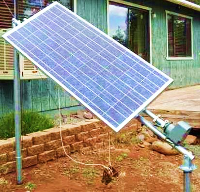 See his video.
*And his webpage.
OK, this is a Bipod variation of a tripod mount.
The tracker uses a TV Antenna Rotator controlled by a time based smart rotator controller.
He sells plans to build this.
teslonian
MrTeslonian's PV Polar Axis Tripod Mount
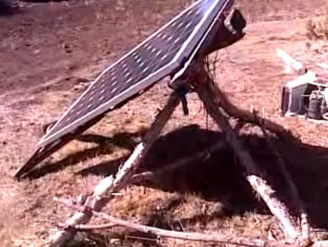 An interesting manual tracked design
While he doesn't have an automatic solar tracker this shows that very simple tracking mounts can work.
It's not rocket science.
pvc
PVC plastic TriPod Mount
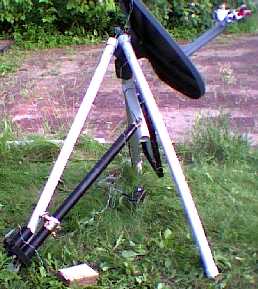
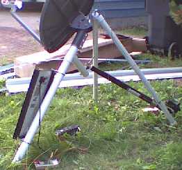
pvccon
This is my version of Poulek's mount. I call it the "TriPod Mount". This mount is cheap and crude but easy to make,
especially for demonstrations. It's easy to build and knock down. It's quite portable.
A proposed Stationary Receiver Dish on a Tripod Mount.
A proposed Stationary Fresnel Lens on a Tripod Mount.
It's made from PV plastic sewer pipe.
1. The legs are fitted with end caps.
2. The foot caps are drilled and have long bolts protruding through to be pushed into the ground.
3. The support legs have "I" bolts fitted to the top caps.
4. The main polar axis leg has a large bolt that is fitted through the "I" bolts of the support legs.
(The Primestar mount doesn't allow the pipe to go all the way through so I made a compromise and have this large top bolt mounted to the dish support. Although the Primestar mount has a method to manually adjust for declination.)
5. The polar leg needs to rotate. To do this side pipes are glued on to the polar and one of the support legs.
6. The satellite dish linear actuator is fitted to the side pipes.
7. To set it up just adjust the support legs until the polar tube is aimed at the pole star. This is due north and angled at exactly your latitude.
8. To make sure the thing doesn't blow away I have a heavy nylon cord, ( not in the pictures ), tied from the top of the polar leg down to the earth. I used a screw into the ground dog leash stake.
9. Don't bolt the dish and PV panel to tightly. This will allow some manual adjusting.
There are some compromises to this example.
1. The actuator can only rotate the polar leg about 150°. A better way would be to have a pulley and cable to get the rotation to 270° or so.
2. The Primestar mount is not ideal. A better mount would allow the polar leg to protrude fully.
3. A longer polar leg would allow more rotation without interfering with the supporting legs.
Improvements
1. For larger equipment one should make the tripod from steel cold water pipe. This would make things much sturdier.
2. Make the polar rotating device using a large pulley and cable to allow more rotation.
3pt
3pivot
3pivottripod
*Hilber Solar Solwing-T
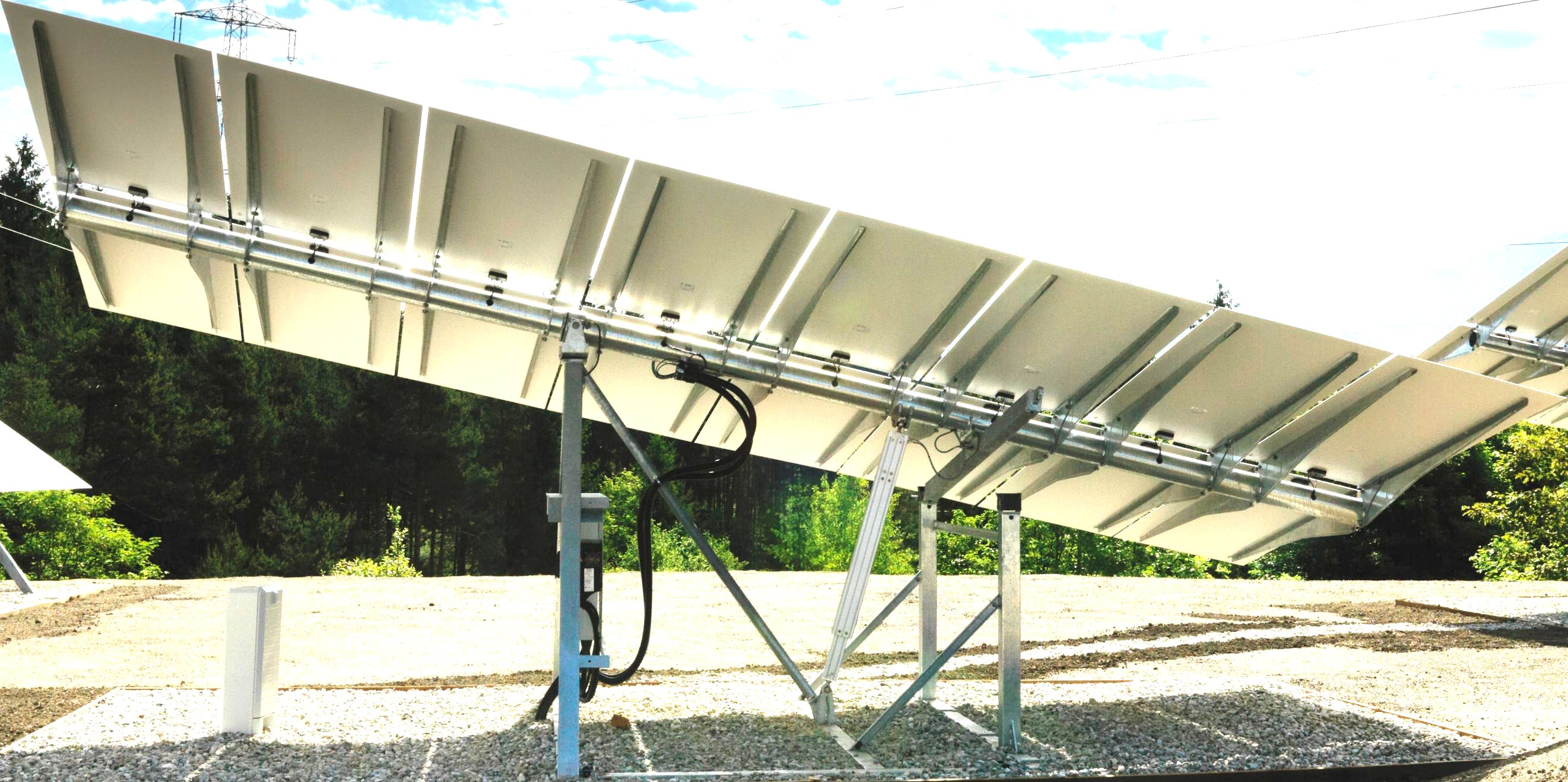
Underside of Hilber Solar Solwing-T
Hilber Solar Solwing-T Anime
3 Pivot Point Tripod Tracking Mount from the Patent
Hilber's Solwing-T is a special case of a 2 Pivot Tripod mount, it has an extra pivot.
1. When tracking to the East the panel is attached to the eastern low end pivot.
2. When at solar noon both low end pivots are in contact. The western pivot is engaged and the eastern is disengaged.
3. When tracking to the West the panel is attached to the western low end pivot.
Watch the .gif above.
If you watch closely you can see that in addition to the normal Right ASCension motion there is also some AZimuth motion. All done with a single linear actuator and the latch mechanism.
This example is set to quite a low LATitude maybe 30°. However, with higher LATitudes like where I am, 45°, or even higher LATitudes such as England, 55°, the sunrise and sunset AZs are quite far north. all things to more closely resemble dual axis mount.
Now this motion is not precise but a lot closer than the 2 Pivot Tripod Mount. It's good enough for flat panels. However, the cost of the mount is considerably more than 2 Pivot mounts. Its interesting though.
"back to 2 Pivot Tripod"
4ph
4pivot
4pivothorizontalaxis
4 Pivot Horizontal Tracking Mount
4 pivots are the minimum but can be more in multiples of 2.
4 Pivot Point Horizontal Tracking Diagram viewed from the north or south end.
In researching the 3 Pivot Tripod mount I can see the latching mechanisms could be useful for another mount.
Utility Scale PV systems use cheap PV Panels mounted on long rows of N/S Horizontal mounts.
The height of the main axis is ½ the panel width plus the Ground Clearence.
PW = Panel Width
GC = Ground Clearence
SH = Support Height
PW/2 + GC = SH
It occurred to me it would be advantagus to have the SH equal to just the GC or so.
Furthermore, when parked flat everything would be closer to the ground decreasing the suseptability to wind damage.
I'm thinking the cost may be lower than my other 20KW design.
PW = Panel Width
GC = Ground Clearence
SH = Support Height
GC = SH
4phus
For Utility Scale Mounts
2 strings of multiple supports with latching pivots mounted on top, PW apart, and GC high.
The length between supports al long the line is dependent on how many panels the material can handle.
4phfr
For Flat Roof Application
In this special case the roof is flat and about 12' E/W by 15' N/S. The special requirement is everything must be able to park flat to the deck, or at least close to the deck, so it can't be seen from the street. (London, go figure?)
I'm suggesting that 4 latching pivots be used at the 4 corners. The linear actuator hangs over the north end to do the lifting.
There are 3 different motions:
1. Latch the 2 eastern pivots and tilt up to the east.
2. Latch the 2 southern pivots and tilt up to the south.
3. Latch the 2 western pivots and tilt up to the west.
4. Latch all 4 when parked flat at night.
Of course, a micro, (probably a MicroMite 5.3), will be used to coordinate the several different movements. In order to switch from one tracking direction to another it is required to fully retract before switching the latches.
Interestingly enough, the panel array could be wider and longer than the roof and it would still work.
Unlike the original Hilber latch which, mostly, only needs to rotate in one plane the southern latches in this scheme needs to move in 2 planes.
I think this latch may need to incorporate a U-Joint, not a Heim-Joint, (Star-Joint in England), which is to limited in movement.
Lets go further:
Say, the panels is a hexagon with 6 corners. 6 latches at each corner would allow the panels to move in 6 directions.
"back to 2 Pivot Tripod"
led4
LED4 LED Sensor Electronic Tracker with Simple Solar Charge Controller.
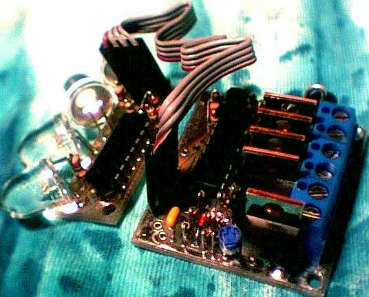 LED4
LED4
The "LED3" light sensor works very well. It is sensitive, accurate, and cheap. A couple of years ago I had devised a simple solar charge controller I called "Shunt 2". I thought it would be a good idea to combine them into a single PC board called the LED4.
Note! I no longer sell the LED4 as it was replaced by the much more capable LED3X. Ok, the LED3X doesn't have a charge controller but this isn't really required to run the tracker.
The design philosophy for this tracker was to make it more robust and self contained. I included a charge controller for rechargeable batteries intending them to be NiCds to run the actuators. Since the charger is there it might as well be capable of running a large PV panel with lead acid batteries.
Note! this charger is not intended to charge the expensive system batteries. Leave that job to the high end smart charger such as those by Trace, Outback, and others.
It can also run a very small PV panel to charge the local NiCds or NiMH batteries. These batteries work well over a wide temperature range.
I will test the ability of the sensors to be at the end of a long cable. I will test this using 1000' of 4 wire telephone cable. 8 wire Cat5 cable should also work with the extra wires driving the actuators.
With the use of long Cat5 cable the main board can be inside a heated battery room. Of course you still have to run the heavy gauge main charging wire pair to the battery room. The advantage of having the batteries in a heated room is temperature compensation won't be needed.
ledshex4
led4features
LED4 Features
| Separate LED Light Sensors |
The signal sent back from the sensor can be sent a considerable distance since the current flow is minimal. However, static electric discharge could be a problem if the sensor is more than about 6 feet or so from the main board. If long distances are needed please Email me for advice. |
| Under voltage Shutdown Protection |
Shuts down the actuator motor drive when the battery voltage drops below about 10½ volts. |
| Built In Charge Controller |
Designed for use with nominal 13.8 volt battery systems. The charger is designed for controlling 13.8 volt 125 watt PV panels. There is no provision for either temperature compensation or multiple charging strategies. |
| Larger Power Transistors |
The power MOSFET transistors are much more robust than in the LED3. It uses IRF5305 and IRLZ44N transistors from International Rectifier. The IRF5305 P-channel MOSFET has an on resistance of about 60mΩ and the IRLZ44N N-channel MOSFET has an on resistance of about 20mΩ. |
| No need for a heat sink |
A 125 watt PV panel can deliver about 9 amps of current. The maximum wattage dissipated by the IRLZ44N shunt transistor under these conditions is about 1.6 watts continuously. The Schottky Barrier series protection diode is rated for about 9 amps.
The H-bridge transistors are pulsed at about a 10% duty cycle. I'm rating the actuator maximum pulsed current at about 16 amps. If you want to continuously drive the actuator keep it below 5 amps.
The IRF5305 has a maximum current rating of 110 amps and the IRLZ44N has a maximum current rating of 160 amps so if the currents are kept to below my system rating no heat sinks will be needed. |
| Built with Through Hole Components |
Through hole construction allows the average home brew guy the ability to easily put the LED4 tracker together either as a kit or scratch built.
I can supply the PC boards separatly for $9.00us.
|
| Operating Temperature Range |
-40°F to 185°F or -40°C to 85°C |
vdish1
Virgil Vinz's faceted dish with LED4 tracker in a plastic Peanut Butter Jar Weather Dome.
This dish is to be used to run a small steam engine. The mirrors are 6" Lucite squares. The ribs are cut from parabolic sections.
The receiver is a flash tube type. The spiral copper tubing is cast into an aluminum block. The Pyrex cooking dish is the transparent insulating cover. The backside is insulated with fiberglass. The indicated temperature is about 1100°F. The concentration ratio is about 20X or so given the receiver is larger than the mirror tiles.
concentratortemperature
Calculations of Concentrator Temperature Rise.
A number of people have asked the question:
"How hot will my concentrator get?"
or:
"How much concentration will I need to get to a certain temperature?"
Let's use this example:
"A twelve foot dish focused to a 6 in., 3 in., or one 1 in., diameter receiver.
How can you estimate the temperature of the various smaller diameters?"
Lets review:
X factor is the ratio of the captured sunlight area divided by the radiating surface area of the receiver. Assuming the back side is well insulated.
12' foot C-band satellite dishes have a focal length of about 10'. At least mine does.
The sun has an image diameter of about 1/2° of arc. At 10' this perfectly focused diameter would be:
( 2 * tan( .5° / 2 ) * 10' = .087' * 12"/1' = 1.04"
That's for a perfect parabola. C-band dishes aren't nearly that accurate. So maybe the diameter is about 3".
So firstly, you can't get to a 1" diameter.
3" is about (144"/3")2 = 2304X
6" is about (144"/6")2 = 576X
"How can you estimate the temperature of the various smaller diameters?"
The simple answer is you can't. Temperature of a receiver is only loosely related to X.
The more important factors are:
1. Rate of heat removal.
   For instance if the heat removal is infinite then
   the temperature would be the same as ambient.
2. The selectivity of the surface of the receiver.
   Good selective surfaces such as black nickel oxide
   are pretty good and will attain a higher temperature
   due to not radiating as much heat back to space.
3. A limiting factor is the surface temperature of the sun.
   Generally considered to be about 10000°F/5600°C.
4. The quality of the reflectivity of the mirror.
   I usually assume this at 80% to 85% regardless of what
   the manufacturer of the Mylar films say.
Another way to help in the understanding of receiver temperature is it's a kind of balance of gains vs losses.
The dish appears to cover a portion of the hemisphere and delivers heat.
The receiver looses heat through the insulation on the back side and radiates into a hemisphere of space.
The ratio:
(dish angular surface area) / (a hemisphere) * 10000°F = Temp
This implies that a receiver temperature is independent of X.
And this Is True. However, larger receivers have other losses such as:
1. Convection loss
2. Process heat removal
What are you trying to do?
Generate steam?
Steam receivers don't have to be particularly small as the temperatures are limited by the steam system.
See our experimental receiver above.
This dish has a no thermal output temperature rise of about 1100°F with a concentration of about 20X. We estimate this is about correct for the dish angular area.
sphericalcollectormath
* Here is an Excel spreadsheet to do the math.
http://www.redrok.com/sphericalcollectormath.xls
Another way to use this information on our system.
1100°F =  0% efficiency. ( No output of steam.)
  50°F = 100% efficiency ( Perfect cooling of the receiver.)
Other efficiencies are approximately linear between these.
 837°F = 25%
 575°F = 50%
 312°F = 75%
Actually the lower temperatures will have higher efficiencies because convection losses are reduced.
Does this make sense?
martins
<Martin Szymanski's> variation of a Tripod Tracking Mount
assemblyled4
Assembly Instructions for the LED4.
opperatingled4
Operating Instructions for the LED4.
Actuator.
I have more circuits here along with a bunch of data about Satellite dish linear actuators. The circuits on this page are not finished nor fully tested.
chace1
Jeremiah Chace's Analog Solar Tracker Schematic.
 Chace1
Tracker Schematic.
Some guys on the net have expressed a desire for a simple analog solar tracker to operate their concentrator projects. Jeremiah Chace sent me a schematic for such a tracker. His circuit was based on a Cadmium Sulfide, CdS, photo cell with a relay output. There were a couple of problems with the circuit. After some discussions with him I made some improvements and here are the results.
The basic operation is essentially that of 2 separate photo sensor circuits in pairs. Each separate sensor circuit has a control pot to set it's sensitivity for bright sunlight.
It is important to have a thorough understanding of the operation of the circuit in order to be successful in making the correct adjustments for acceptable operation. One must do the adjustments on a clear cloudless day. At the very least wait until the sun is between clouds.
CdS cells have a wide variance in the resistance they exhibit in bright sunlight. Generally the resistance is too low for this type of circuit. I have found that the CdS cells can be modified to have higher resistance by painting the cells with a black marker. I use a Sharpie black permanent marker. I paint this on all sides and edges. If you get too much on it can be removed with fingernail polish remover or acetone.
The correct amount of blackening is when the adjustment pot is approximately at mid setting when the circuit is tilted so about half of the cell is illuminated by sunlight and half covered by the light blocker. Repeat this painting of the cells until all 4 CdS cells are adjusted.
I have found a helpful tool to make the adjustment easier. Just use a small mirror to reflect sunlight onto the CdS cell. By covering one cell with the finger and reflecting light onto the other cell the tracker can be moved at will. This allows the cell sensitivity adjustments to be easily made.
The painting procedure would not be very easy to get accurate were it not for the pot. The settings seem stable but I haven't had very much time on the circuit. I suspect that the most problem would be the fading of the black marker. If this happens I suppose a different more permanent light filter coating could be devised. Possibly Parsons Black which is carbon lampblack in spar varnish.
P.S. I have had about 4 months of operation on the tracker and have not seen any problems.
There have been days where no bright solar radiation falls on the sensors the tracker just stays in the last position that movement occurred. The panel is not at the optimum orientation to gather the maximum amount of energy from this diffuse radiation during these times.
In the long run this is not a problem. Of course the amount of energy is less than optimum during cloudy times. The gain due to tracking greatly exceeds the dim time loss.
chaceshadow
Sensor and shadow light blocker.
Each CdS cell of a pair is on each side of a central light divider with a top light blocker. The light blocker is just wide enough to block both CdS cells when the sun is dead on center. In this example the light divider is made of rubber and the light blocker is an old aluminized 5.25" floppy disk write protector. The materials used are not critical. They need only be light opaque. The light divider should be black and non reflective. The blocker could be made from reflective aluminum foil to prevent heat buildup.
Note! The CdS cells are highly angled in such a way that they are generally aimed at a portion of the sky that is away from the sun. This helps to get the platform moving in the right direction when far off track.
If either CdS cell is uncovered by the light blocker it will conduct heavily and the associated power driver will move the actuator in such a way that the CdS cell is again covered.
When neither CdS cell is exposed to bright light the actuator is prevented from moving. This leaves the tracker at the last moved to position. Little power is expended searching for a new position when in dim light.
The light blocker is supposed to never let both CdS cell be exposed to bright light. However it could happen. If this condition occurs the actuator is prevented from moving or hunting. This saves power by moving only when necessary.
This schematic is for one axis. The second axis is the same as the first and uses the other half of the LM339 comparator.
When the sun is behind clouds the actuator is prevented from moving or hunting. When the sun comes back out the tracker will move toward it again.
When the sun sets the platform remains aimed to the west. In the morning the easterly aimed CdS cell becomes active and the platform positions itself back to the east.
In my example I have the light dividers about 2 inches long. If a tighter angular tolerance is desired the light dividers can be made longer.
Overall Layout.
The layout of the circuit has the CdS cells mounted on the eastern side of the board. The east/west, right ascension, pair is on the left. The north/south, declination, pair is on the right. The output power drivers are in the foreground.
I have mounted the power MOSFETs in such a way that they form the output terminals. Another example is pictured in my heliostat I/O board shown here:
Terminals.
The PC board is all single sided using mostly 1/4 Watt resistors and capacitors mounted in surface mount fashion. This prototype construction technique is fast and easy to build. If the board is to be built in larger quantities a through hole board could be build with the parts in exactly the same location as the surface mount version.
(Any one want one? Email me at: <redrok@redrok.com>)
Here is my 1998 US cost breakdown in single quantities.
IRF9Z34    $1.82 *  4 = $7.28 Digi-Key
IRFZ34     $1.25 *  4 = $5.00 Digi-Key
LM339      $ .49 *  1 = $0.49 Digi-Key
resistors  $ .02 * 20 = $ .47 Digi-Key
Pot D4AA15 $ .22 *  4 = $ .88 Digi-Key
CdS Cell   $ .35 *  4 = $1.40 Jameco
Total                  $15.42
A true surface mount board using conventional, tiny, surface mount parts would make the board about 1/2 the present size. All the components are available in surface mount form except the CdS cells. Even the power transistors can be had in surface mount.
I don't think that the smaller sized board layout justifies the higher cost of the surface mount components.
Weather Dome.
How do you like the high tech weather dome? It is made of a 2 liter polyethylene plastic pop bottle. This plastic is pretty good in the UV of sunlight. Of course it can be easily replaced if it becomes clouded. Use the bottles with the black plastic base and remove it. The fancier Coka Cola bottles with the molded in feet don't work very well optically.
I think a 1 liter bottle would work just as well and the wooden mounting would be smaller. I haven't tried a 1 liter bottle yet.
The dome is not sealed from the weather in the picture. I will drill a hole in the wooden mount for the wires. The tapered sides to the wooden block will seal the dome to the block. The interior gets hot enough to vaporize any condensed moisture.
goofy1
Experimental Goofy Demonstration Mount.
I needed a platform to test the circuit. I usually don't want to publish an untested circuit. I have had experience with circuits that don't operate as expected the first time. I sent Jeremiah a prototype, (Rev. A2), of the circuit and PC board to try out on his dish. Unfortunately he is moving his shop and couldn't try it out right away. I then decided to build a simple mount that I had been thinking about for a while.
This is a simple design meant for use with PV panels. It uses 2 satellite dish linear actuators. One to move the platform east and west about +-75°s in right ascension. The other to move the platform north and south a minimum of +/-23.5°s in declination.
The main pier is slanted to the south at an angle of 90° - the local latitude, (45°s for me). The reason the pier is tilted south is to align the right ascension axis to the polar axis which is the bolt that holds the ascension member to the pier. A second brace will be installed under the pier for support if needed.
Right Ascension / Declination Head.
This is a close-up of the mount head. The declination mechanism is controlled by the second satellite dish actuator. It tends to move the declination platform around the axis on the ends of the right ascension mechanism.
This picture shows the arrangement of the two satellite dish linear actuators. These actuators have adjustable limit switches. These switches are required by this circuit both to limit the travel and stop power from being wasted when at the limits.
Actuators with limit clutches are unsuitable for this application. While they do stop when the limit is reached, their motor continues to consume power. This is disastrous when running on a storage battery. The actuators, which consume over 10 amps, will drain the battery in a short while.
The magnitude of the declination movement is maximum when at the extremes of the right ascension and minimum in the middle of the travel range.
This design leaves a lot to be desired.
| 1. | It has limited travel.
|
| 2. | The declination angle changes in a complicated way with the movement of the right ascension angle.
|
| 3. | It probably is not very strong when at the extremes of travel. I used it only as a convenient means of testing the analog controller.
|
patent5622078
Brad A. Mattson's Active Solar Tracker Patent# 5512742 & 5622078.
 Brad's PV Solar Tracking Panel and Controller.
 This is one of Brad's patents for this mechanism.
bradtrough
Brad's Trough Collector.
This is Brad's patent for the solar tracking controller.
shunt
charger
Solar Charge and Diversion Controllers.
Most solar charge controllers are of the shunt type. They are easy to build and work very well. More complex controllers are the Maximum Power Point Controllers.
I will describe several circuits that are based on a Zetex ZM33064 computer voltage monitor and reset circuit. While there are a number of companies and models of voltage monitors on the market I chose the Zetex ZM33064 because of its low cost, accuracy, low power consumption, but mostly for the low, 20mV, hysteresis characteristic.
Most reset circuits operate in a similar manner to the Zetex ZM33064 and could be substituted in the circuits.
I believe that power controllers based on voltage monitor circuits are significantly reduced in complexity due to the high integration of several power controller characteristics in a small 3 pin device that looks like an ordinary TO-92 transistor. In come cases it and a power MOSFET transistor are the only active devices in the circuit.
shunt1
A Simple Solar Shunt Charge Controller.
This is the simplest charge controller that I know of. OK, a really big zener is simpler but I don't know where to get one that can do the job. I have built several of these for different purposes and they work OK but I don't recommend there usage anymore because more advanced circuits exist today.
Shunt1
Simple Shunt Charge Controller.
These parts can be obtained from:                        Digi-Key or Farnell.
 5  Amp 40 Volt Diode                   $0.63us        SB540CT-ND     518177
12 Volt  1 Watt Zener Diode             $0.26us    1N4742ADICT-ND     368660
 1  Amp 50 Volt Diodes                  $0.60us/10  1N4001DICT-ND     365117
10  Amp 25 Watt NPN Power Transistor Q1 $1.00us     approximately
7.5 Ω   50 Watt Power Resistor       RL $3.22us      FVT50-7.5-ND
Total                                   $5.17us
Of course you will also need a 25 watt heat sink for the transistor.
I don't know why but Digi-Key dropped their bipolar power transistors. You can get any NPN power transistor capable of dissipating 25 Watts possibly from Radio Shack.
This is a version of an amplified zener diode with a Schottky diode used to prevent power loss through the panel at night.
shunt2
A Better Solar Shunt Charge Controller.
Here's A better Solar Shunt Regulator. It can be made as large as you want. It's not as "simple" but it works better.
Shunt2
Shunt Charge Controller.
These parts can be obtained from:                       Digi-Key or Farnell.
 5     Amp 40 Volt Schottky Diode         $0.63us     SB540CT-ND     518177
 5.1  Volt .5 Watt Zener Diode            $0.21us 1N5231BMSCT-ND     368970
 8.2  Volt .5 Watt Zener Diode            $0.21us 1N5237BMSCT-ND     369020
41     Amp 55 Volt Logic Level MOSFET Q1  $1.73us     IRLZ44N-ND     637488
 4.6  Volt ZM33064 Voltage Monitor        $1.74us    ZM33064C-ND     633318
 1  K  Ω   Trim Pot                   R2  $0.22us      D4AA13-ND
 2.0K  Ω   .25 Watt 5% Carbon Film    R1  $0.28us/5 2.0K E BK-ND
24K    Ω   .25 Watt 5% Carbon Film    R3  $0.28us/5  24K E BK-ND
Total                                     $4.86us

With Optional Heater Resistor

 2     Ω   100 Watt Resistor          RL $12.45us  AVT100-2.0-ND
Total                                    $17.31us
Is this cheap enough?
How the Conventional Shunt Charge Controller circuit works.
This shunt regulator is based on a Zetex ZM33064 computer under voltage reset circuit.
The voltage monitor is an integrated circuit in a 3 pin package that in its normal usage is used to reset a microprocessor. The IN pin would normally be connected to a 5V logic bus.
When the 5V bus voltage drops bellow 4.6V the open collector OUT pin is pulled down toward ground.
In my circuit I use this output to switch the gate of a logic level power MOSFET.
When the voltage is bellow 4.6V the transistor is turned OFF and the PV panel is allowed to supply power to the battery until the voltage goes above 4.6V. The Zetex ZM33064 has a hysteresis of about 20mV which is degraded to 100mV in the circuit. This helps to prevent the power MOSFET from going into linear mode and dissipating power in the transistor. When in regulation the transistor will switch On and OFF at a rate dependent upon the capacity of the battery and power available from the PV panel.
The zener and resistors are used to divide the battery voltage down to the 4.6V range for the voltage monitor.
Don't skimp on the power MOSFET. You might ask why use a transistor capable of passing 41 amps in a circuit designed for only 5 amps. The answer is in the cost and complexity of the heat sink. This transistor has only .022 Ω s of ON resistance. This power dissipation at 5 Amps is:
7 * 7 * .022 = 1.1 Watts. The transistor will get warm but not excessively and without a heat sink.
Of course if the full 41 amps is passing through the transistor then:
41 * 41 * .022 = 37 Watts. This is significant and needs to be heat sinked for this amount of heat.
damage
Damage Your Panel With A Shunt Controller. Not!!!!
You might ask if there is a problem with the direct shorting out of the PV panels?
Will this shorting damage the PV panels?
The simple answer is NO!
I have talked to several PV panel manufacturers. All have said there are no detrimental effects to their panels.
Now for the more complex answer.
One of the reasons that you might want to use the optional heater resistor instead of directly shunting the panel is that the panel will run slightly cooler, which is a good thing.
Think of it this way. when the panel is delivering it's peak load at a nominal efficiency of 15% much of the other 85% is dissipated as heat in the panel. If the panel is either open circuited or shorted then no power is delivered to the load and 100% of the influx is dissipated as heat in the panel. The shunt resistor, if selected properly, will have a voltage, not 0 volts, across it and dissipate nearly the same power that would have been delivered to the battery. The result is that the temperature of the panel will remain more constant.
OK, so this is only a minor point but I wanted to explain it thoroughly. I suspect that environmental conditions, such as clouds passing by, vary the temperature far more than that caused by any power regulator. Besides, the manufacturers say there isn't a problem here anyway.
I used the high current 41 Amp MOSFET because when operated at low currents it will dissipate only negligible power and prevent over heating.
The optional heater resistor can be used to heat something such as water or the house in winter. It's not needed. Normally the transistor dead shorts the panel. This is not an error. It's standard practice for solar panels to be shorted in this way. There is no harm to the panel doing this.
If you do use a large heat sink on the transistor this regulator is capable of much higher currents. Possibly as high as 41 Amps. (I haven't done this myself yet.)
The MOSFET power driver circuit probably should be improved for very high currents during regulation. The best improvement would be to use a D flip flop between the voltage monitor and the transistor gate. This flip flop is clocked at about 100 Hz. This will cause the transistor to have a controlled and predictable gate pulse.
shunt3
The Best Solar Shunt Charge Controller.
Here's the Best Solar Shunt Regulator. It's more complicated but it works better because it's temperature compensated.
I have adding temperature compensation to the basic shunt PV regulator. Temperature compensation is needed when the battery pack is stored in a location where the temperature is not controlled, such as outside and near the PV panel, in hot or cold weather.
Depending on the manufacturer, the charge voltage is adjusted by measuring the battery temperature. The specific value is mainly dependent on the internal RESISTANCE of the battery. This resistance is basically dependent on the CHEMICAL ACTIVITY in the battery. This chemical activity is dependent on the TEMPERATURE.
The construction methods can also affect the change in internal resistance vs. temperature.
temperature
Most lead acid batteries have a temperature coefficient somewhere between:
-.0025 V/(°C * Cells) the minimum temperature coefficient.
-.0036 V/(°C * Cells) being recommended by Bill Dubè if no other information is known.
-.0040 V/(°C * Cells) being recommended by Hugh Piggott.
-.0050 V/(°C * Cells) the maximum temperature coefficient.
13.8 Volt Lead Acid Battery Voltage vs. Temperature
| °C | °F | LM50 Output | -.0050 V/(°C * Cells) | -.0040 V/(°C * Cells) | -.0025 V/(°C * Cells)
|
| 50°C | 122°F | 0.900V | 12.34V | 12.75V | 13.07V
|
| 25°C | 77°F | 0.750V | 13.80V | 13.80V | 13.80V
|
| 0°C | 32°F | 0.500V | 16.23V | 15.55V | 15.02V
|
| -20°C | -4°F | 0.300V | 18.17V | 16.95V | 15.99V
|
| -40°C | -40°F | 0.100V | 20.12V | 18.34V | 16.96V
|
Shunt3
Temperature Compensated Shunt Charge Controller.
These parts can be obtained from:                       Digi-Key or Farnell.
 5     Amp 40 Volt Schottky Diode      $0.63us        SB540CT-ND     518177
 5.1  Volt .5 Watt Zener Diode         $0.21us    1N5231BMSCT-ND     368970
 5.1  Volt .5 Watt Zener Diode         $0.21us    1N5231BMSCT-ND     368970
41     Amp 55 Volt Logic MOSFET    Q1  $1.73us        IRLZ44N-ND     637488
 4.6  Volt ZM33064 Voltage Monitor     $1.74us       ZM33064C-ND     633318
    LM2902 Dual Operational Amplifier  $0.49us        LM2902M-ND     400002
           -40°C to 125°C Temp Sensor  $1.47us       LM50CIM3-ND     630937
  1K   Ω   Trim Pot                R7  $0.22us         D4AA13-ND
500K   Ω   Trim Pot                R8  $0.22us         D4AA55-ND
2.4K   Ω   .25 Watt 5% Carbon Film R3  $0.28us/5    2.4K E BK-ND
2.7K   Ω   .25 Watt 5% Carbon Film R5  $0.28us/5    2.7K E BK-ND
 10K   Ω   .25 Watt 5% Carbon Film R4  $0.28us/5     10K E BK-ND
 20K   Ω   .25 Watt 5% Carbon Film R6  $0.28us/5     20K E BK-ND
 91K   Ω   .25 Watt 5% Carbon Film R1  $0.28us/5     91K E BK-ND
200K   Ω   .25 Watt 5% Carbon Film R2  $0.28us/5    200K E BK-ND
Total                                  $7.26us

With Optional Heater Resistor

  2    Ω   100 Watt Resistor       RL $12.45us     AVT100-2.0-ND
Total                                 $19.71us
How's that?! It's cheap and has temperature compensation too!
The bread boarding went well. I now have the circuit working. The LM2902 buffer Op Amp was required because the LM50 has a high impedance output. This output is not designed to drive even very low power powered loads.
The LM50 is a new generation SOT-23 part from National Semiconductor. It reads temperature from -40°C to 125°C. The interesting feature of this sensor is that it outputs 10mV/°C referenced to -50°C.
Vout=(10mV/°C*Temp°C)+500mV for the LM50
| Temp°C | Temp°F | Vout
|
| 125°C | 257°F | 1750mV
|
| 100°C | 212°F | 1500mV
|
| 75°C | 167°F | 1250mV
|
| 50°C | 122°F | 1000mV
|
| 25°C | 77°F | 750mV
|
| 0°C | 32°F | 500mV
|
| -20°C | -4°F | 300mV
|
| -40°C | -40°F | 100mV
|
| -50°C | -58°F | 0mV
|
I mounted the LM50 on a little chip of PC board and soldered 3 wires to it. This allows the sensor to sample the battery temperature. To insulate the LM50 from possible damage I coated it with automotive "Oxygen Sensor Safe" RTV gasket cement from Permatex.
The .47uF capacitor is needed when the LM50 is mounted remotely with wires. It's not needed if the LM50 is mounted near the Op Amp on the PC board.
The two pots are very tricky to adjust because they interact with each other. The best way to set them is to substitute the LM50 with a voltage divider pot. It's also helpfully to substitute a resistor for the battery.
The LM50 makes it easy to substitute an external voltage for the LM50 temperature output voltage. Just force the desired voltage onto the output pin of the LM50 connected to the OpAmp. The LM50 has a high impedance resistor divider output. No damage will occur if the voltage is kept between -1VDC and VCC+.6VDC, +5.7VDC in this case. Of course the two calibration voltages will be .3VDC and .9VDC.
Temporary Test Circuit Used for Calibration.
Adjustment Procedure for Pots R7 and R8.
| 1. | Determine which temperature coefficient you need from the manufacturers literature.
|
| 2. | Introduce 0.300V, equivalent to -20°C, and adjust R8 for the correct output voltage.
|
| 3. | Introduce 0.900V, equivalent to +50°C, and adjust R7 for the correct output voltage.
|
| 4. | Repeat steps 2 and 3 until no more changes are needed to either R7 or R8.
|
I am not entirely satisfied with the circuit because of the sever interaction between the 2 pots when adjusting for different temperature coefficients. I think that one pot should be used to calibrate the sensor and the other to set the temperature coefficient with no interaction between them. I will consider a change in the future. Right now it works, don't fix it.
Right now the circuit is acceptable and works from -40°C to +50°C. I tested it in my temperature chamber. The circuit tracked quite well with temperature.
If you want the most accuracy possible you will have to calibrate the LM50. This is done by measuring the voltage output of the LM50 at two temperatures. Calculate the temperature coefficients for the sensor and introduce them into the standard equation.
Vtemp=(10mV/°C*Temp°C)+500mV
Use this new equation to get the true output voltage for -20°C and +50°C and use them in the R7 and R8 adjustment procedure.
If you want to purchase a commercial shunt controller check out the Morning Star units at:
Windsun
or:
Natural Energy Systems, Inc.
undervoltage
Under Voltage Protection.
Damage to the battery or load equipment can occur if the storage battery charge is run down to much.
This could happen in many application such as these:
| 1. | Sign Lighting. | The battery could be under charged for the nights lighting requirements and could become depleted.
|
| 2. | Remote Instrumentation. | The battery could be under charged if the weather has not allowed enough solar energy to accumulate. In this case critical measurement equipment could be left running while unnecessary equipment is turned OFF. In my case the Peet Brothers Ultimeter 2000 weather monitor remains ON while the Kenwood 7930 2 meter transceiver is turned OFF. The weather monitor continues to record data.
|
| 3. | Water Pumping. | In water pumping applications it is sometimes desirable to have the pump operate on a continuous basis, even at night. A storage battery supplies the night time power to run the pump. However, if the charge gets below 50% the battery life suffers. Under voltage cutoff protection can solve this problem.
|
| 4. | Domestic Electricity. | The battery could be depleted due to excessive usage. In this case critical equipment, such as the computer, furnace, or refrigerator, could be left running while unnessassary equipment is turned OFF.
|
| 5. | Sensitive Equipment. | Some equipment must be shut OFF when the battery voltage is low. My Kenwood 7930 2 meter transceiver doesn't tolerate low voltage well.
|
Undervoltage
Under Voltage Protection Circuit.
 These parts can be obtained from:                         Digi-Key or Farnell.
   8.2 Volt  .5 Watt Zener Diode          $0.21us    1N5237BMSCT-ND     369020
  18   Volt  .5 Watt Zener Diode          $0.21us    1N5248BMSCT-ND     931688
 -17    Amp -55 Volt P channel MOSFET  Q2 $1.82us       IRF9Z34N-ND     934677
    .1  Amp  40 Volt NPN Transistor    Q3 $1.60us/10  2N3904DICT-ND     358824
   4.6 Volt ZM33064 Voltage Monitor       $1.74us       ZM33064C-ND     633318
2.00K   Ω   .25 Watt 1% Carbon Film    R1 $0.54us/5   2.00K X BK-ND
2.26K   Ω   .25 Watt 1% Carbon Film    R2 $0.54us/5   2.26K X BK-ND
  10K   Ω   .25 Watt 5% Carbon Film    R9 $0.28us/5     10K E BK-ND
  20K   Ω   .25 Watt 5% Carbon Film    RH $0.28us/5     20K E BK-ND
 200K   Ω   .25 Watt 5% Carbon Film    R3 $0.28us/5    200K E BK-ND
 Total                                    $4.52us
How the Under Voltage Protection circuit works.
This Under Voltage Protection Circuit is based on a Zetex ZM33064 computer under voltage reset circuit.
The voltage monitor is an Integrated Circuit in a 3 pin package that in its normal usage is used to reset a microprocessor. The IN pin would normally be connected to a 5V logic bus.
When the 5V bus voltage drops bellow 4.6V the open collector OUT pin is pulled down toward ground.
In my circuit I use this output to switch the Base of an NPN logic transistor, T3, which in turn operates the gate of a standard gate drive level P channel power MOSFET, T2.
The power transistor, T2, is turned ON when the battery voltage is higher than a set point and OFF when below the set point.
When the voltage is above 4.6V the output transistor is turned ON and the load is given power from the battery until the voltage goes below 4.6V. The Zetex ZM33064 has a hysteresis of about 20mV which is degraded to 100mV in the circuit. This helps to prevent the power MOSFET from going into linear mode and dissipating power in the transistor. This amount of hysteresis may not be enough for many applications.
An extra hysteresis resistor, RH, can be added to increase the hysteresis to higher voltages. This could be used to prevent cycling of the protected load. The amount of hysteresis required is dependent on the internal resistance of the battery. When the load is removed, due to low voltage, the battery voltage increases. If the hysteresis is not large enough the protected load will be turned ON again. And the cycle continues.
I can't give you an equation that predicts what this resistor should be. I can only suggest that you experiment with the value until satisfaction is obtained.
The two resistors, R1 and R2, are used to divide the battery voltage down to the 4.6V range for the voltage monitor. The hysteresis resistor, RH, affects this calculation.
Calculate the value of R2 for the Under Voltage Protection Circuit.
Vc     =   10.8V                                          Desired cutoff voltage.
Vm     =        4.6V                                      Threshold voltage of ZM33064.
R1     =                          2.00KΩs                 Lower voltage divider resistor.
RH     =                                  20.0KΩs         Lower voltage divider resistor.
Im     =                                            180µA Quiescent current of ZM33064.
R2     = ( Vc - Vm ) / (( Vm   / ( R1-1 + RH-1 )-1 ) + Im  )
R2     = (  6.2V  ) / (( 4.6V / ( 1.8181KΩs     ) + 180µA )
R2     = (  6.2V  ) / (( 2.53mA                 ) + 180µA )
R2     = (  6.2V  ) / (         2.71mA                    )
R2     =        2.29KΩs
R2     =        2.26KΩs                                   Closest 1% value.
WattsR2= ( Vc - Vm )2 /  R2
WattsR2= (  6.2V  )2 / 2.26KΩs                            Calculate the power in R2
WattsR2=       0.017 Watts                                Use a 1/4 watt resistor.
I now have bread boarded this circuit and it works fine. I made a few changes to the circuit as published before. These were minor value adjustments. I also removed the adjustment pot. Next, I will make a PC board that includes the temperature compensated shunt regulator.
I have shown, on the schematic, two outputs:
| 1. | Bypass. | This output is for critical equipment. It essentially bypasses the protection circuits.
|
| 2. | Protected. | This output is for the equipment that can be turned OFF when the low battery voltage is reached.
|
I have added two optional jumpers:
| J1 | Enable Output. | Enables normal operation of the controlled output.
|
| J2 | Disable Output. | Forces the controlled output OFF.
|
| None | Output ON. | J1 removed Forces the controlled output ON if J2 is not in place. J2, Disable Output, has precedence.
|
I hope that all of these designs will fulfill your needs. Obviously I can't know the specifics of your requirements. Please use general circuit design analysis to determine the proper size of the heat sink or the value and wattage of the optional heater resistance.
Use good judgement when sizing the power MOSFETs for higher power applications. I have attempted to use components that will work with much higher current MOSFETs. One caution is the use of logic level vs. conventional gate drive transistors.
The conventional gate drive transistors require that greater than 10 volts, some even higher, be applied to the gate to be fully turned on. Logic level gate drive transistors may be damaged by this high a gate voltage. Logic level gate drive transistors will be fully ON with 5 volts applied.
Power MOSFET characteristics:
| Gate Drive. | Logic Level Gate Drive Power MOSFETs | Conventional Gate Drive Power MOSFETs
|
| Greater than 5 Volts. | Full rated current flow with low drive voltage. | The transistor may be operating in the linear region which is usually very destructive.
|
| Greater than 10 Volts. | The gate may breakdown with voltages greater than 10 volts. | Full rated current flow.
|
If you have any questions or special requirements about these circuits just send me an Email at:
<redrok@redrok.com>
diversion1
Diversion Controller.
Here's A type of Shunt Regulator called a Diversion Controller. It can be used to dump unwanted charging power into a diversion load once the battery is full.
Diversion1
Diversion Charge Controller.
These parts can be obtained from:                         Digi-Key or Farnell.
 5.1  Volt  .5 Watt Zener Diode            $0.21us  1N5231BMSCT-ND     368970
30     Amp 100 Volt Logic Level MOSFET Q1  $1.73us      IRL540N-ND     740690
 4.6  Volt  ZM33064 Voltage Monitor        $1.74us     ZM33064C-ND     633318
 1K    Ω   Trim Pot                    RD  $0.22us       D4AA13-ND
 2.00K Ω   .25 Watt 1% Carbon Film     R1  $0.54us/5 2.00K X BK-ND
24.3K  Ω   .25 Watt 1% Carbon Film     R2  $0.54us/5 24.3K X BK-ND
24K    Ω   .25 Watt 5% Carbon Film     R3  $0.28us/5   24K E BK-ND
Total                                      $4.17us
Is this cheap enough?
How the circuit works.
The diversion controller works similar to the shunt regulator. In the shunt regulator the source charging current is shunted to ground when the battery is full. In the diversion controller the diversion load is activated when the battery voltage is full.
The diversion controller has no charging diode and does have a diversion load.
This diversion controller is based on a Zetex ZM33064 computer under voltage reset circuit.
The voltage monitor is an Integrated circuit in a 3 pin package that in its normal usage is used to reset a microprocessor. The IN pin would normally be connected to a 5V logic bus.
When the 5V bus voltage drops bellow 4.6V the open collector OUT pin is pulled down toward ground.
In my circuit I use this output to switch the gate of a logic level power MOSFET.
When the voltage is bellow 4.6V the transistor is turned OFF and the diversion load is removed to allowed the power to the battery until the divided voltage goes above 4.6V. The Zetex ZM33064 has a hysteresis of about 20mV which is degraded to 100mV in the circuit for 12V.(I haven't built one of these but I would expect the hysteresis to be 400mV for a 48V battery.) This helps to prevent the power MOSFET from going into linear mode and dissipating power in the transistor. When in regulation the transistor will switch On and OFF at a rate dependent on the capacity of the battery and power available from the PV panel.
The two resistors, R1 and R2, are used to divide the battery voltage down to the 4.6V range for the voltage monitor.
Don't skimp on the power MOSFET. You might ask why use a transistor capable of passing 30 amps in a circuit designed for only 5 amps. The answer is in the cost and complexity of the heat sink. This transistor has only .044 Ωs of ON resistance. This power dissipation at 5 Amps is:
5A2 * .044Ω = 1.1Watts.
The transistor will get warm but not excessively and without a heat sink.
Of course if the full 30 amps is passing through the transistor then:
30A2 * .044Ω = 40Watts.
This is significant and needs to be heat sinked for this amount of heat.
The total diversion load in this example is:
55.2V * 30A = 1656Watts.
The diversion power can be increased by either using a larger transistor, paralleling more transistors, or paralleling more diverter controllers.
Additional diverters can be staged by setting them at slightly different voltages.
Calculate the Value of R2 in the Diversion Controller.
Vc     =   55.2V                                                 Desired Diversion voltage.
Vm     =        4.6V                                             Threshold voltage of ZM33064.
R1     =                      2.00KΩs                            Lower voltage divider resistor.
RD     =                                          1KΩs           Divider Pot
Im     =                                                   180µA Quiescent current of ZM33064.
R2     = ( Vc - Vm ) / (( Vm   / ( R1        + RD / 2 ) )  + Im     )  - ( RD / 2 )
R2     = (  50.6V  ) / (  4.6V / ( 2.00KΩs   + .5KΩs    ) + 180µA ) - ( .5KΩs )
R2     = (  50.6V  ) / (  1.84mA                          + 180µA ) - ( .5KΩs )
R2     = (  50.6V  ) / (  2.02mA )                                  - ( .5KΩs )
R2     =    25.05KΩs                                                - ( .5KΩs )
R2     =    24.55KΩs
R2     =    24.3KΩs                                              Closest 1% value.
WattsR2=    R2        * (( Vm  / ( R1        + RD / 2 ) ) + Im    )2
WattsR2=    24.3KΩs   *    2.02mA2                                Calculate the power in R2
WattsR2=             0.099 Watts                                  Use a 1/4 watt resistor.
* Here is an Excel spreadsheet to do the math.
http://www.redrok.com/DiversionController.zip
pwm
mppt
Pulse Width Modulating, PWM, Solar Power Regulators.
Maximum Power Point Controllers, MPPC.
Maximum Power Point Trackers, MPPT.
The Maximum Power Point Tracker is a special form of buck/boost, sometimes buck only, power converter designed to deliver the maximum possible power to a load, or storage battery, from limited input power sources. These work similar to a normal Pulse Width Modulating, PWM, voltage regulator except that the pulse width control is designed to track the maximum power available from the PV panel. Of course, when the battery voltage is high enough then the converter is shut down effecting charge regulation.
PV panel output voltage, and consequently the maximum power point, varies in many ways. The maximum power point varies with temperature, light influx, cloud cover, dirt, and panel age. The important thing is that this maximum power point voltage rarely matches the battery voltage.
These converters are sort of reverse voltage regulators that instead of controlling the output voltage, which is fixed by the battery, it controls the input voltage.
There are several ways to accomplish the control of this power conversion:
| Fixed Ratio.
| The simplest way is to just manually set the pulse width of the power converter. While this is not technically a controller because the pulse width is fixed it does produce some power gain over a shunt controller.
|
| Open loop power tracker.
| A better way is to first characterize the panel voltage vs. the input light vs. output power. A photo sensor circuit controls the input voltage at which the panel runs. While these work reasonably well and more efficiently than the simple regulators they are not the optimum solution. In my opinion they are no cheaper to build than the better tracking circuits described next.
|
| Closed loop power tracker.
| More complicated and more accurate power tracking controllers use wattage sampling techniques to continuously find the optimal panel operating voltage. The way they work is to periodically introduce a small change in the controlled panel input voltage, measure the current, then calculate the input wattage. If the wattage has increased over the last sample then the next change in voltage should be in the same direction as the last change. However, if the wattage is less than the last sample the next voltage change should be in the opposite direction to what the present change was.
OK, I said the power was measured on the input to the converter. Actually the wattage can be measured on either the input or the output.
The panel voltage is continuously being adjusted in a dynamic way to see if the output power can be increased. While the panel voltage is technically never at the true peak power point the error is negligibly small. The result of this voltage dance is the ability of the controller to track the maximum power point no mater what the input PV panel conditions.
|
Can the circuit be made simpler? YES!
| Closed loop current tracker. | It turns out that there is a major simplification in the control of maximum power point tracking battery charger controllers. Yes, this is a special case, not the general case. Delivered power is the multiplication of delivered current times battery voltage. Since battery voltage is relatively constant one needs to only use the delivered current to represent the approximate delivered power. No complex multiplication needs to be performed.
In the above example where power was used to determine the direction of the change of the input voltage The simplified controller uses the change of the delivered current sample as the clue for determining the direction of the change of the input voltage.
|
I built a controller for a windmill alternator in about 1973 that used OpAmps and CMOS logic gates. Today I think I would use a simple microprocessor to do the controlling. The idea though is this type of circuit doesn't need to be complex, This isn't rocket science.
Many micros have built in AtoD converters and PWM outputs. Use the AtoD to measure the output current and the PWM to control the pulse width of the pass transistor in the buck/boost converter.
Future Plans:
I am planning on designing an MPPT. I will be using a desktop PC as the logic element. I will use a simple buck circuit with the PWM controlled by the computer. A 1 bit integrating current sampling AtoD circuit will tell the computer if the power delivered is increasing or decreasing. The computer will always be slowly changing the pulse width wider or narrower. The direction of change is controlled by the polarity of the single bit AtoD.
I have done these experiments. It was successful.
I now plan to program a PIC micro processor to perform the function. The PIC with which I'm interested is the PIC12C672. This microprocessor is in an 8 pin dip. It has 4 A/D converters, an internal clock and is cheap. I hope this micro will do the job. I will keep you posted.
(Gees, that was a while ago. Yes It worked nicely. However, since I figured out the details and I don't think I can compete with the big guys on price this is where I left it. Today I would use a PIC12F675.)
Any questions or comments? Email me at:
<redrok@redrok.com>
For further study on how MPPTs work look at the various patents on the subject at my Neat Patents page:
http://www.redrok.com/neat.htm#MPPT
Conclusion:
If the power grid is available then there is no need of any form of PV nor other alternative power sources. The power grid provides a very stiff power source and can accommodate the use of simple low cost power supplies for most applications. However, not everyone has access to the power grid. Some also want that feeling of energy independence.
Conventionally, PV panels have been the mainstay alternative energy source. They are also very expensive. MPPTs are a solution to increasing the power delivered by the PV panels. If the costs of the MPPT is low enough, and I think they are, the total cost of the power delivered can be reduced.
MPPTs can benefit many applications where the input power is not very constant. Many alternative energy sources have highly compliant output power curves and require a more sophisticated power converter than a simple power supply. If one wishes to maximize the delivered power from highly compliant power sources MPPTs are what is required.
MPPT can increase the power output of a PV system by about 20%. Much greater gains in power can be obtained by using solar trackers which constantly aim the PV panels at the sun. I estimate about 100% increase in power output in summer and 50% increase annually, and about even in winter can be obtained from solar tracking.
The combination of solar tracking and MPPTs is an unbeatable combination.
If you want to purchase a good MPPT check out the Solar Converters, Inc. unit at:
windsun

Windsun, owned by Warren Lauzon.
solarconverters

Solar Converters Inc.
solarstar

SOLASTAR, Solar Powered Water Pumps.
rvproducts

RV Products, solar battery charging, monitoring, inverters and panels for your complete electrical independence!
Here is a circuit in the "Ideas For Design" column of Sep.14,1998 ELECTRONIC DESIGN.
Maximum-Power-Point-Tracking Solar Battery Charger
by W. Stephen Woodward.
Here is an article from Feb.4,1999 EDN magazine.
Harness solar power with smart power-conversion techniques
by Allan Petersen, Maxim Integrated Products.
PV to DC motor MPPT
Build this simple Mini Maximiser
by Alan Hutchinson, Plasmatronics, Melbourne
Circuit complete with PC board layout.
efficiency
Cost Efficiency in MPPTs, Maximum Power Point Controllers.
Now it can be argued that the cost of the MPPT controller is more expensive than adding an extra panel or 2 especially if it gains only about 20% over the shunt regulator. Also the MPPT is a single point of failure if only one is in the system.
This is a site to get the data to compare different collector types.

For my location in Minnesota I get:
| 2 axis flat plate | June | 8-10KWHr/m2/day
|
| Flat Plate Tilted Lat+15° | June | 4-5KWHr/m2/day
|
| 2 axis flat plate | Annual | 6-7KWHr/m2/day
|
| Flat Plate Tilted Lat ° | Annual | 4-5KWHr/m2/day
|
| 2 axis flat plate | December | 3-4KWHr/m2/day
|
| Flat Plate Tilted Lat-15° | December | 3-4KWHr/m2/day
|
If I weren't a tinkerer I don't think I would purchase one for my system. I think a solar tracking panel rack would be more cost effective. These can deliver double the power output in summer and 40% in winter instead of only a gain of 20% in efficiency as with an MPPT and it's cheaper to boot. Warren Lauzon points out that in the middle of winter when the flat plate tracking collector is about even with non tracking collectors the MPPT has the advantage.
<redrok@redrok.com>

 I use Electronics Workbench Personal Edition.
 I generally design circuitry that uses surface mount soldering techniques.
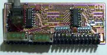
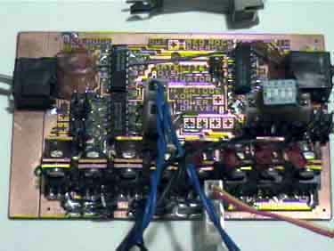
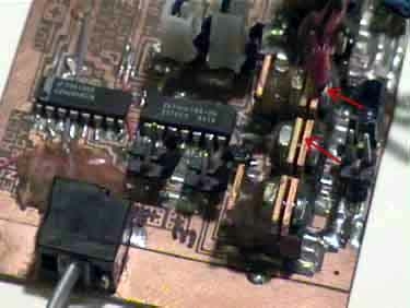
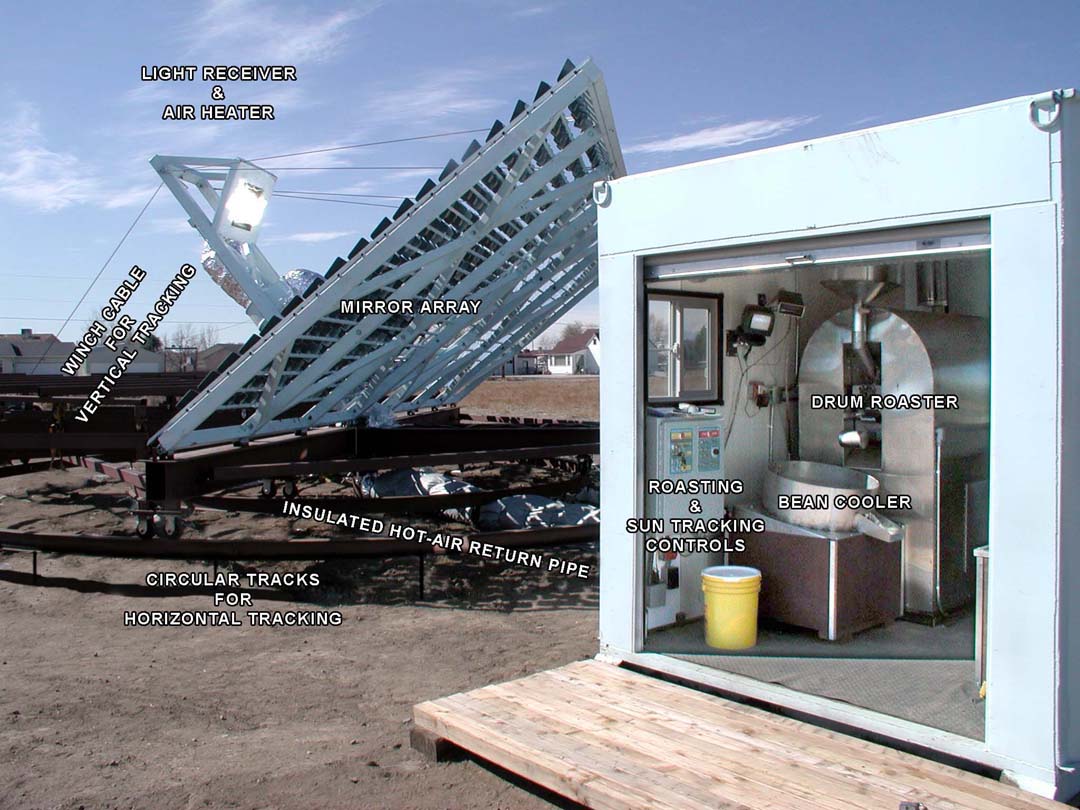
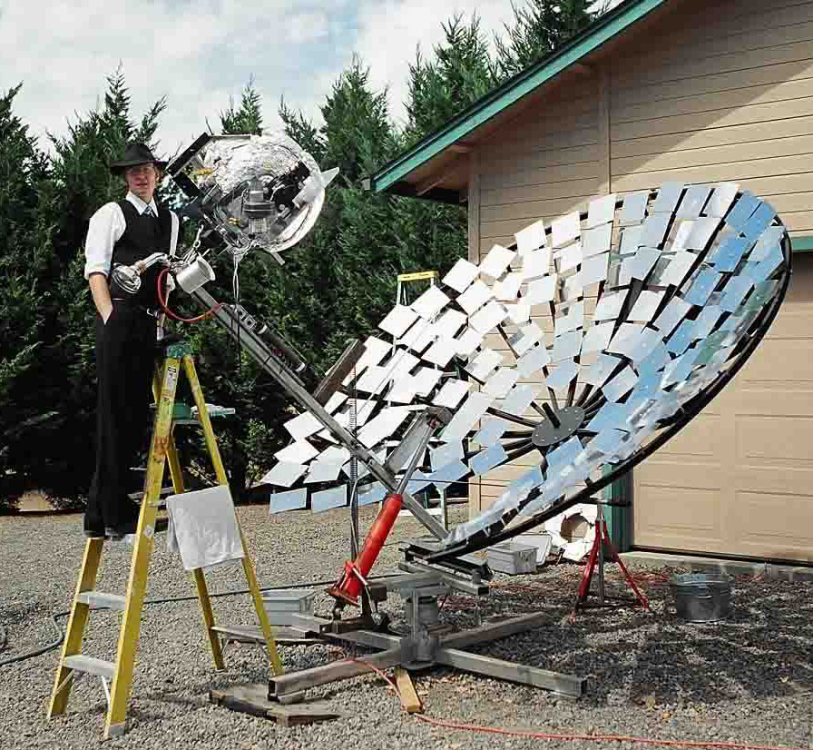

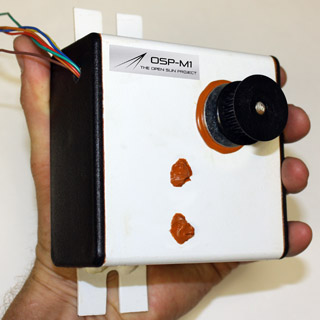 * Open Sun Project Stepper Motor.
 * SunSeeker Project
 * "Rich DeMartile" <rich_demartile@prodigy.net>
 * The Analog Guy Solar Trackers:
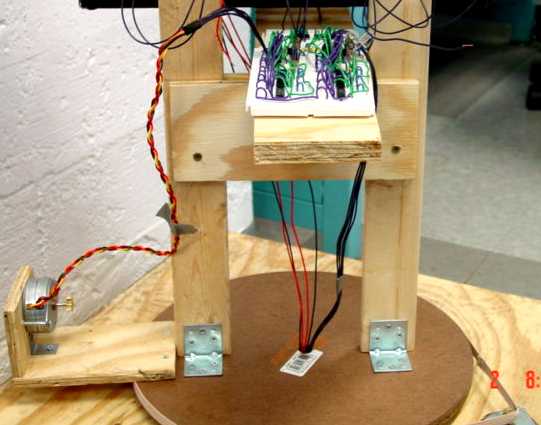
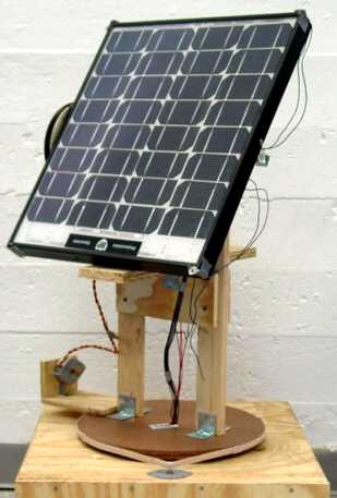
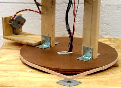
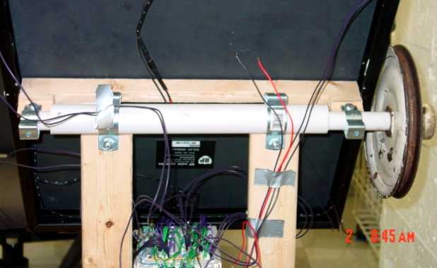
 CdS1
CdS1 LED1
LED1 LED2
LED2

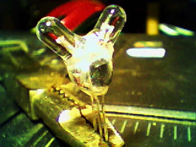
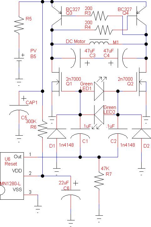 LEDSE
LEDSE
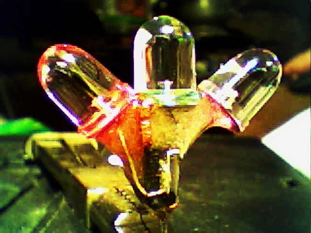
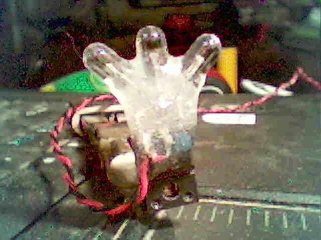
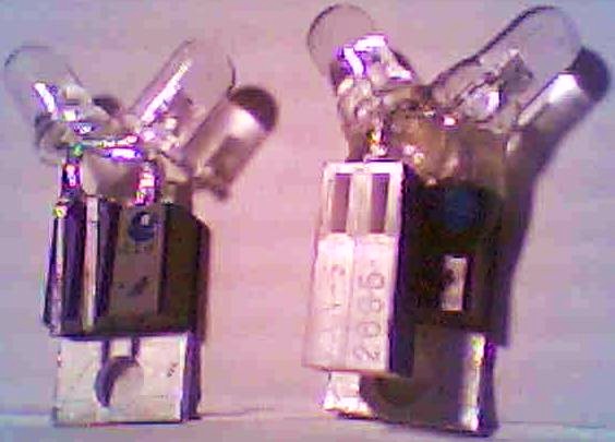
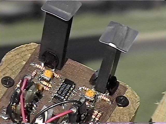 The circuit board and sensor assembly of the Chace tracker.
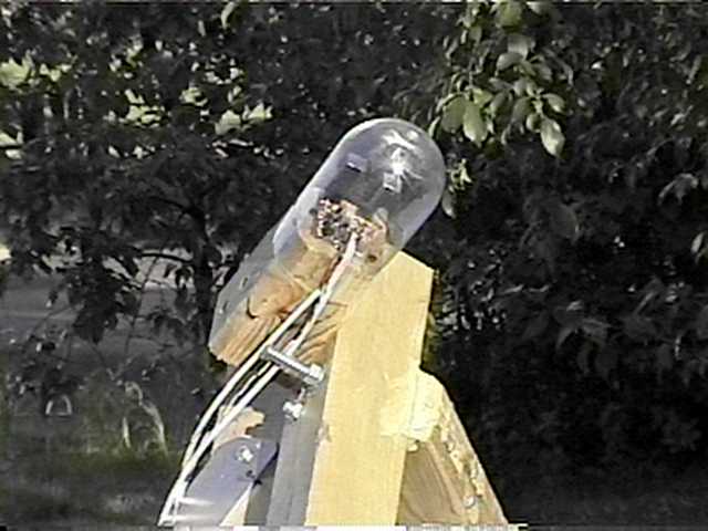 Dome on Chace tacker
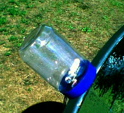
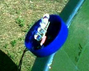
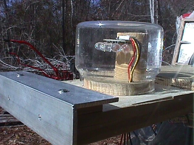
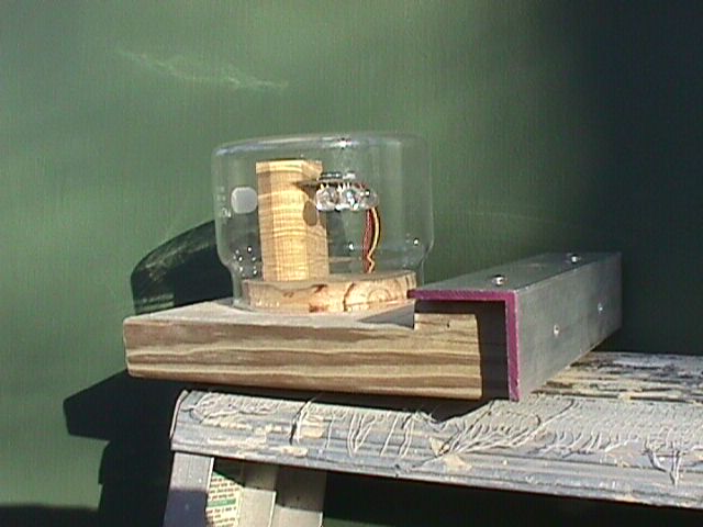
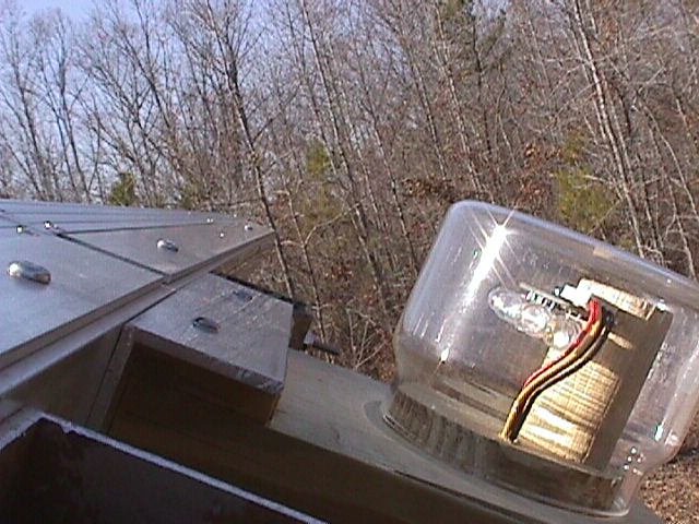
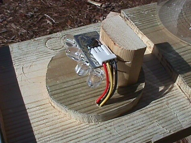

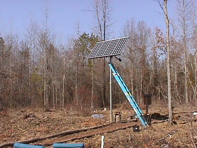
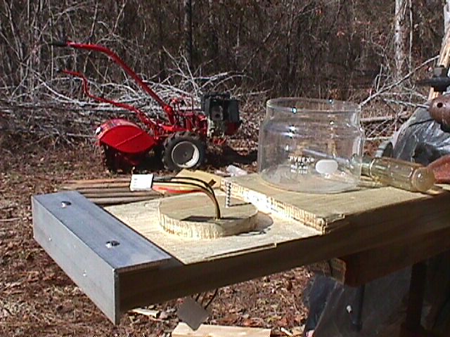
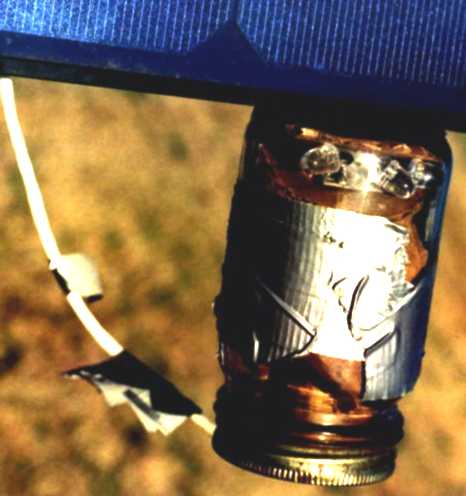
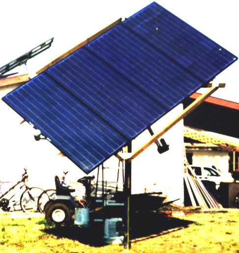
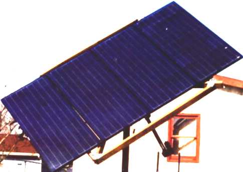
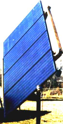
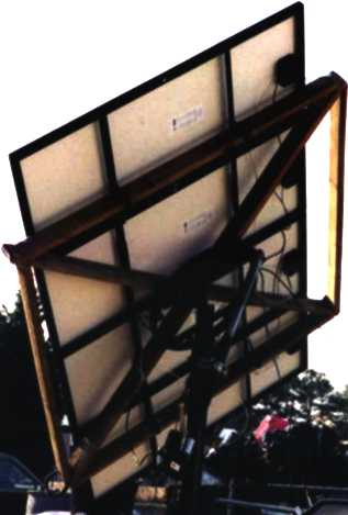

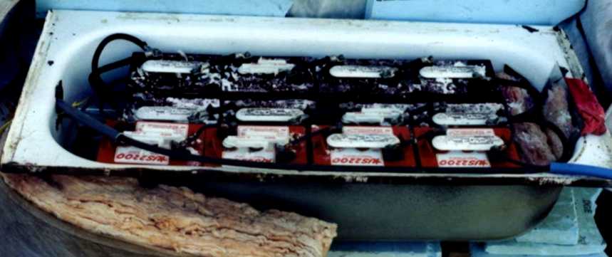
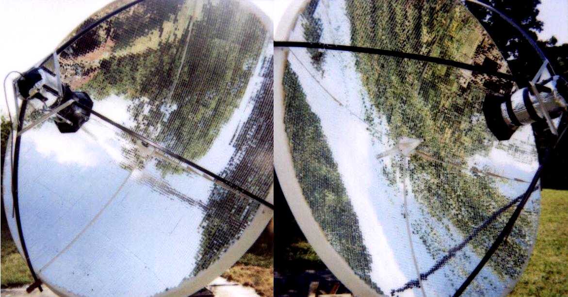
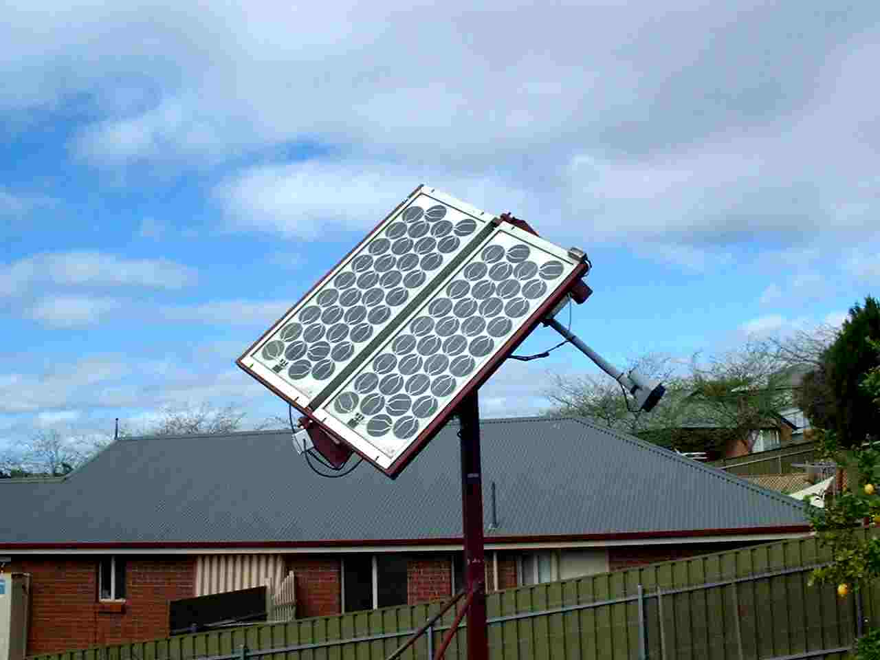
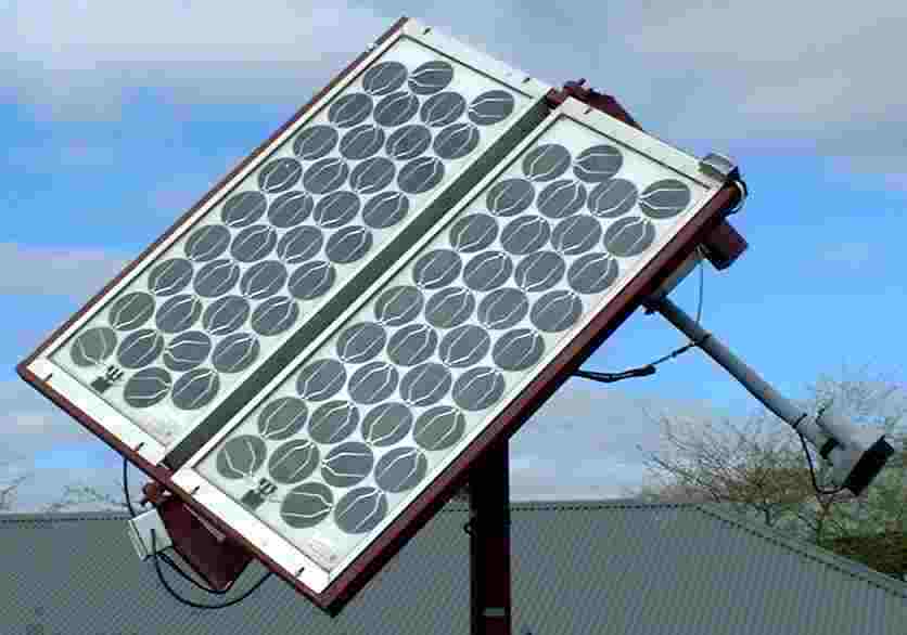
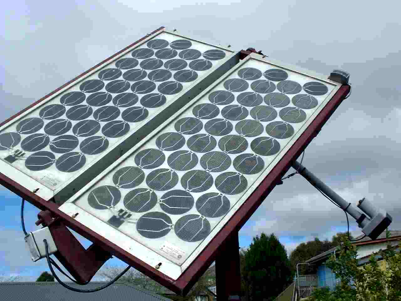
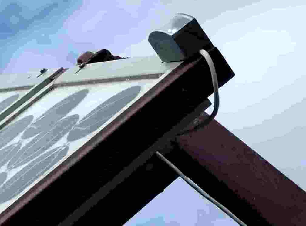
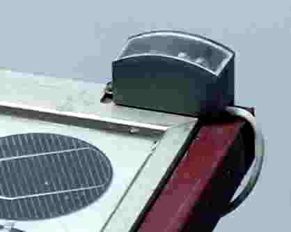
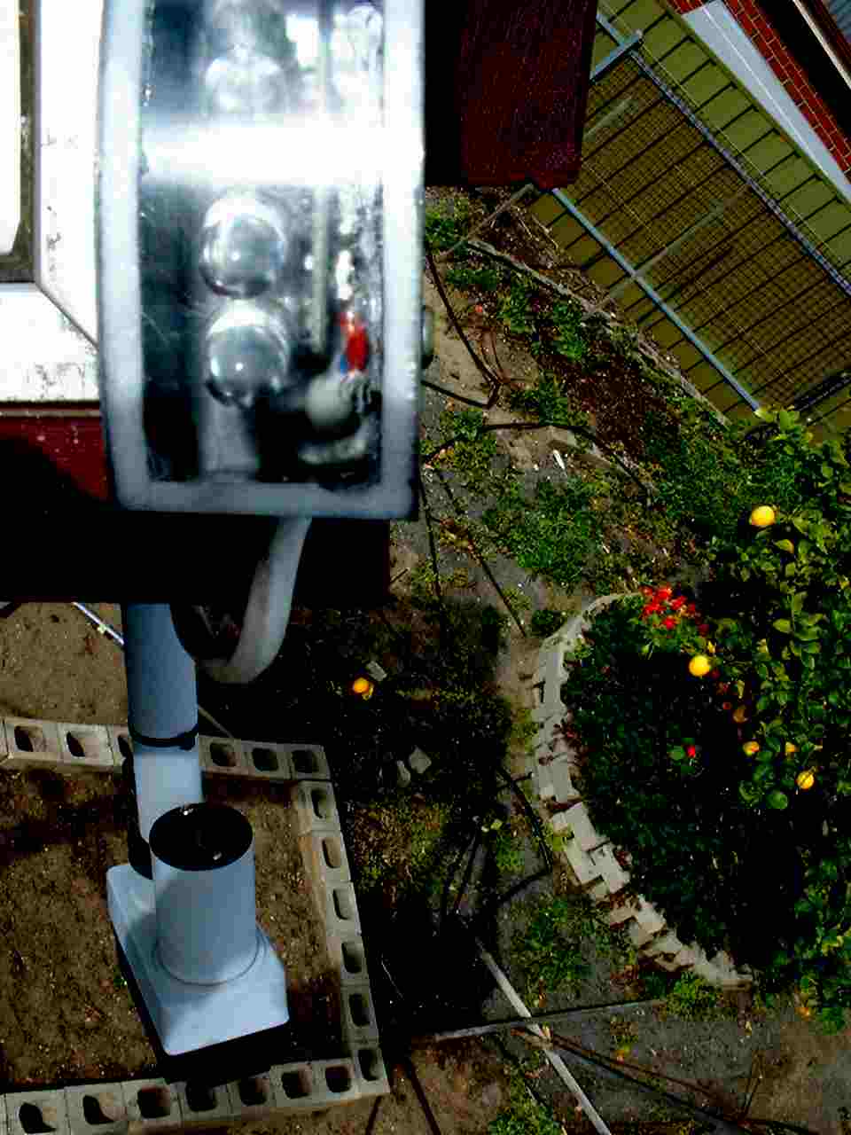
 LED3 Schematic
 Molex Connector
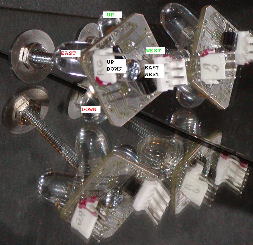
 Click the map!

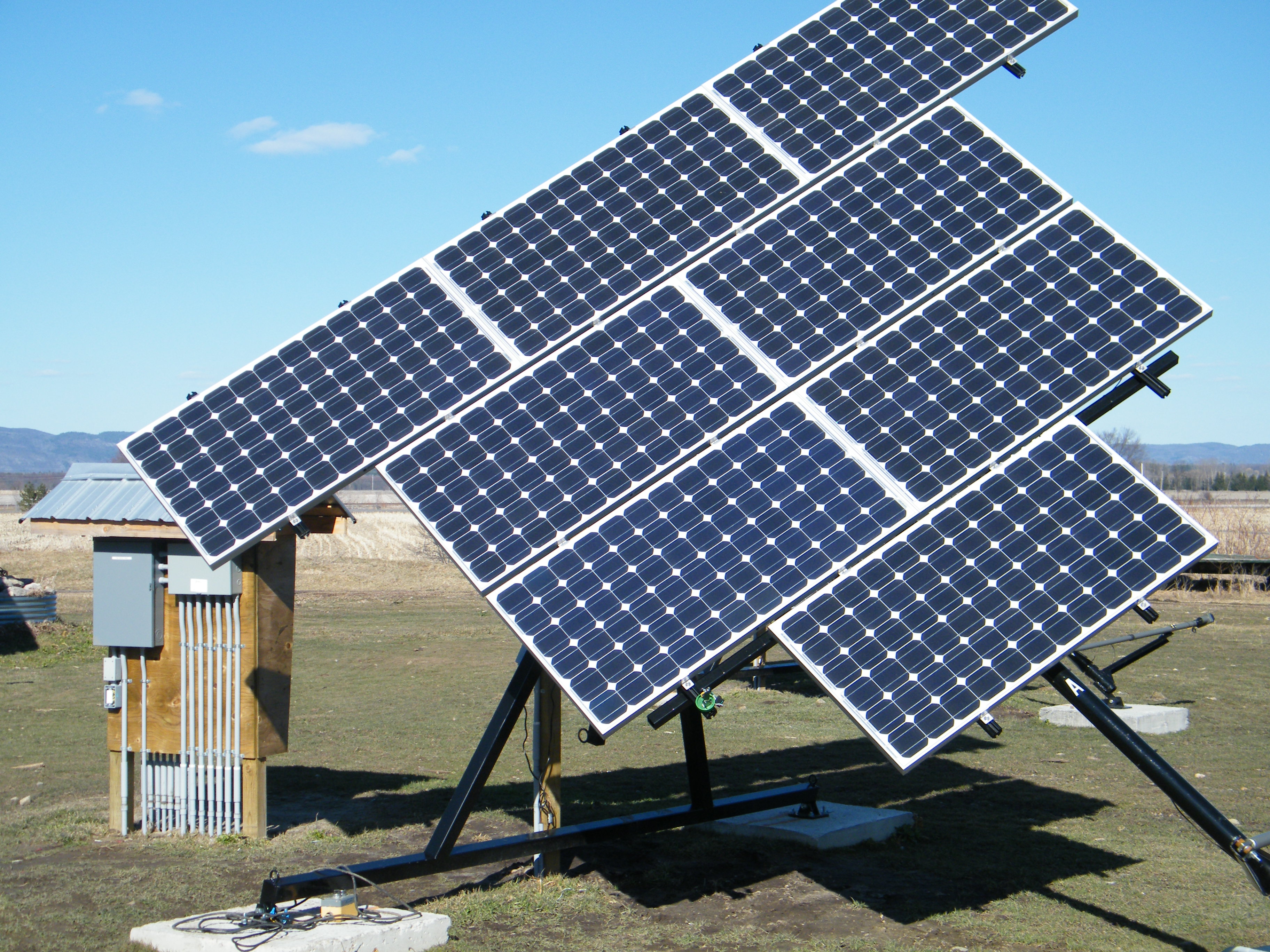
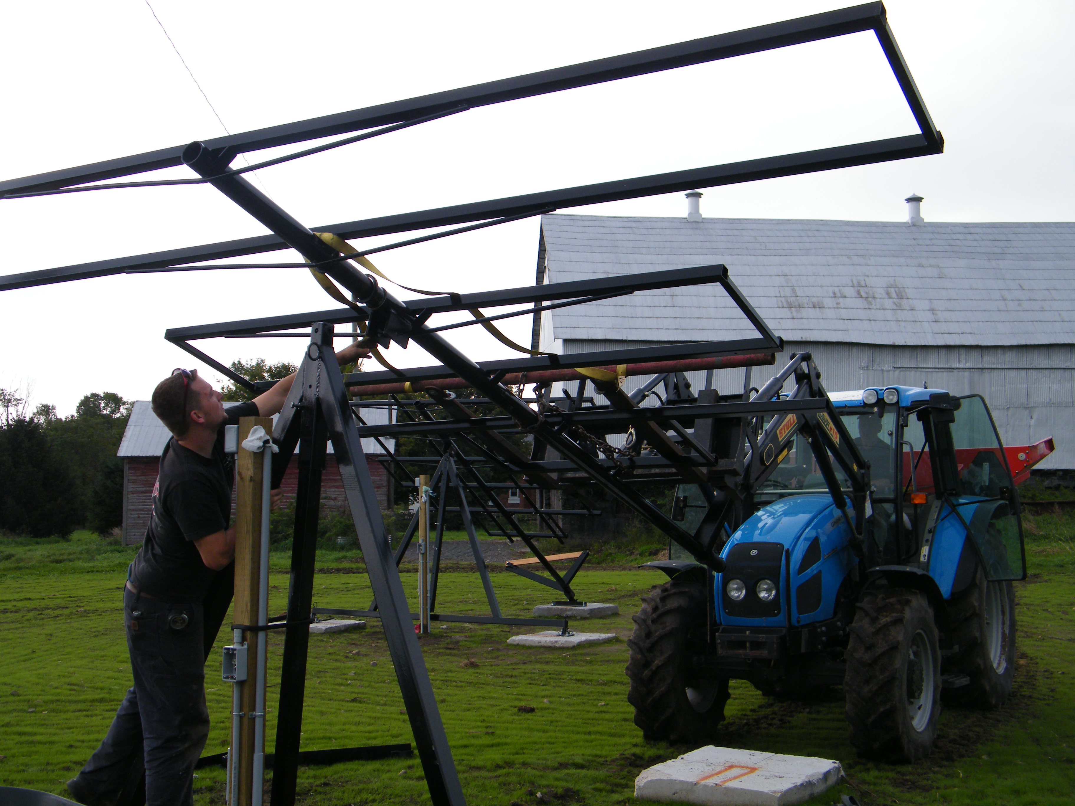
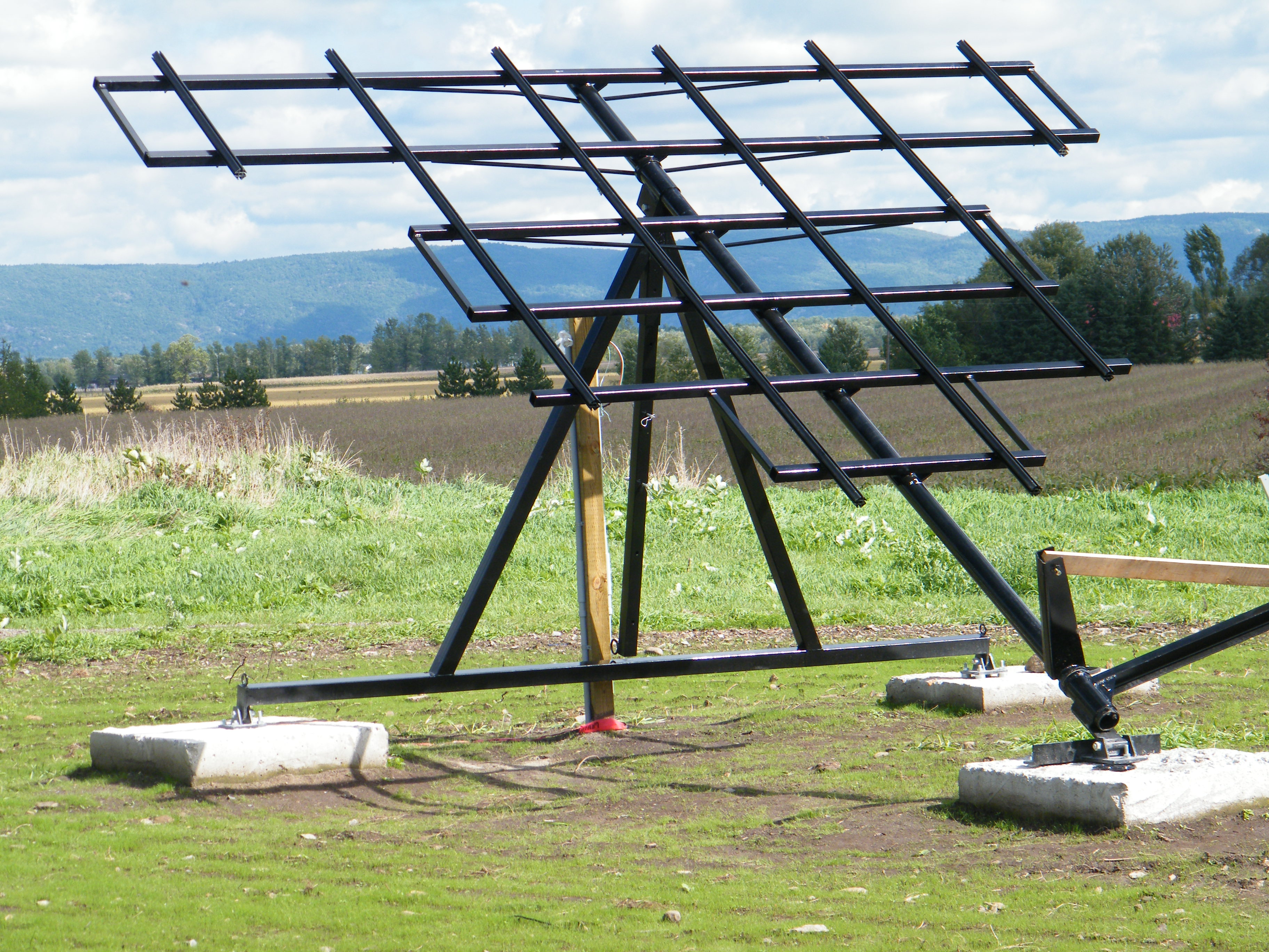
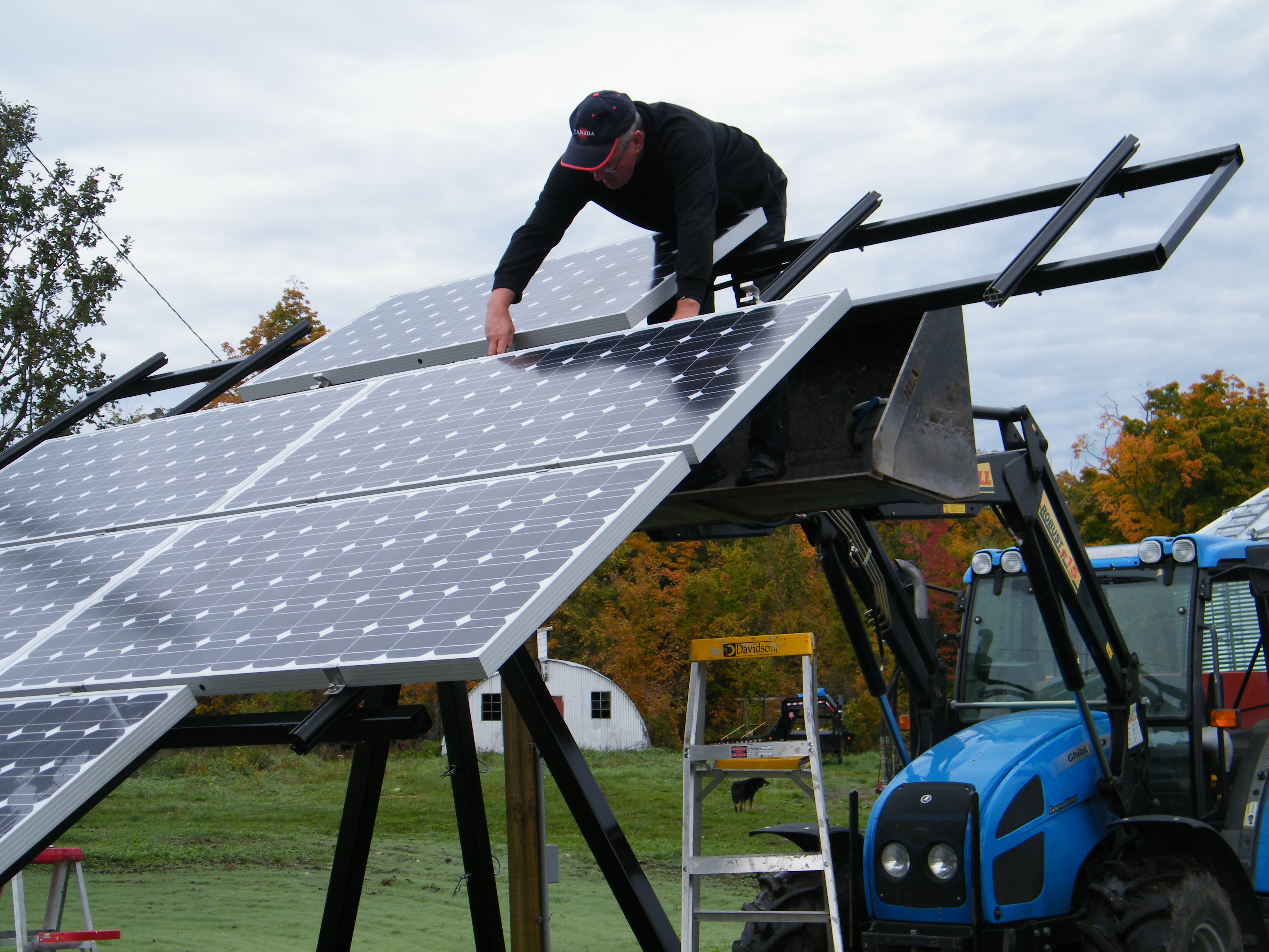

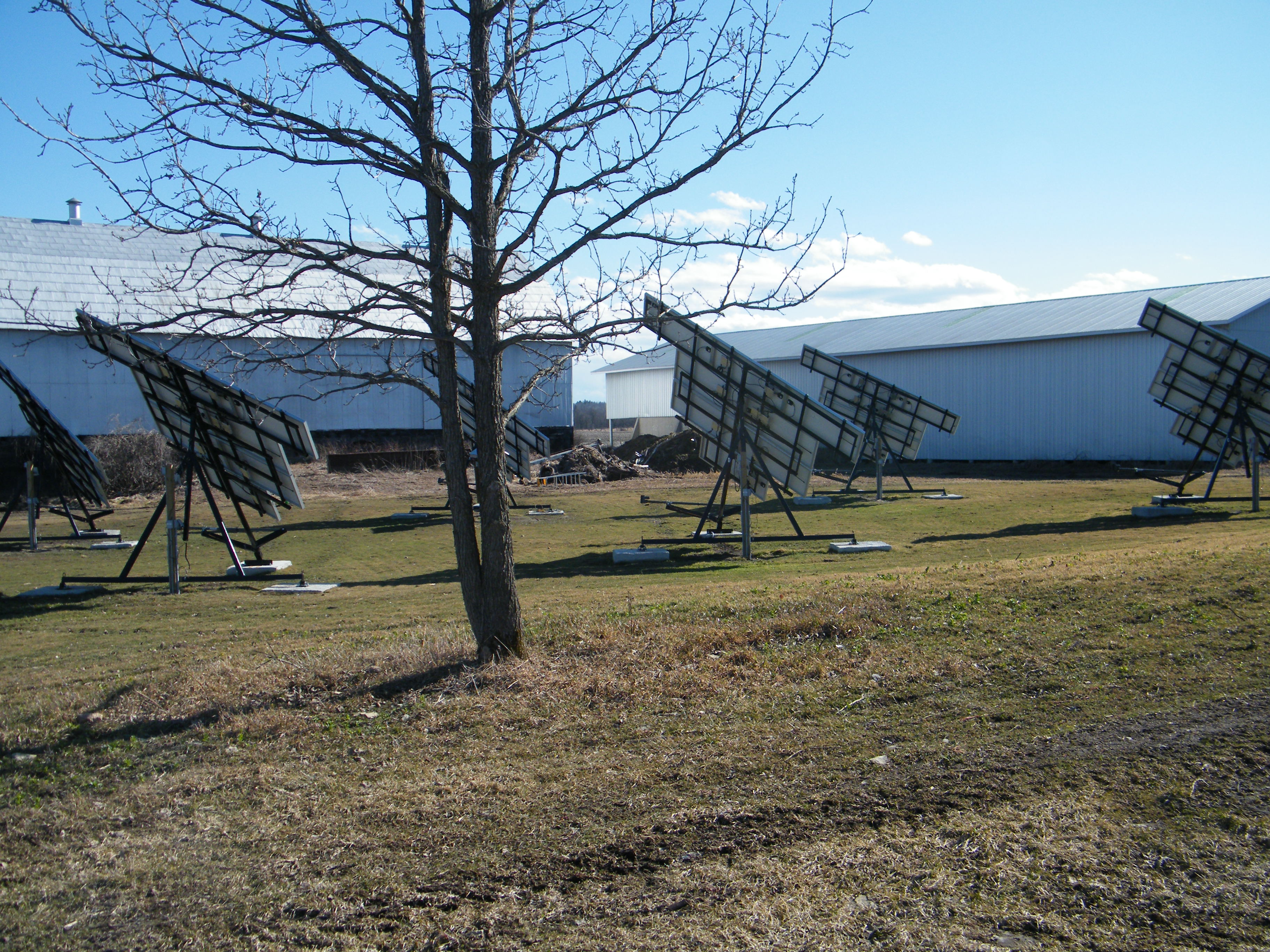
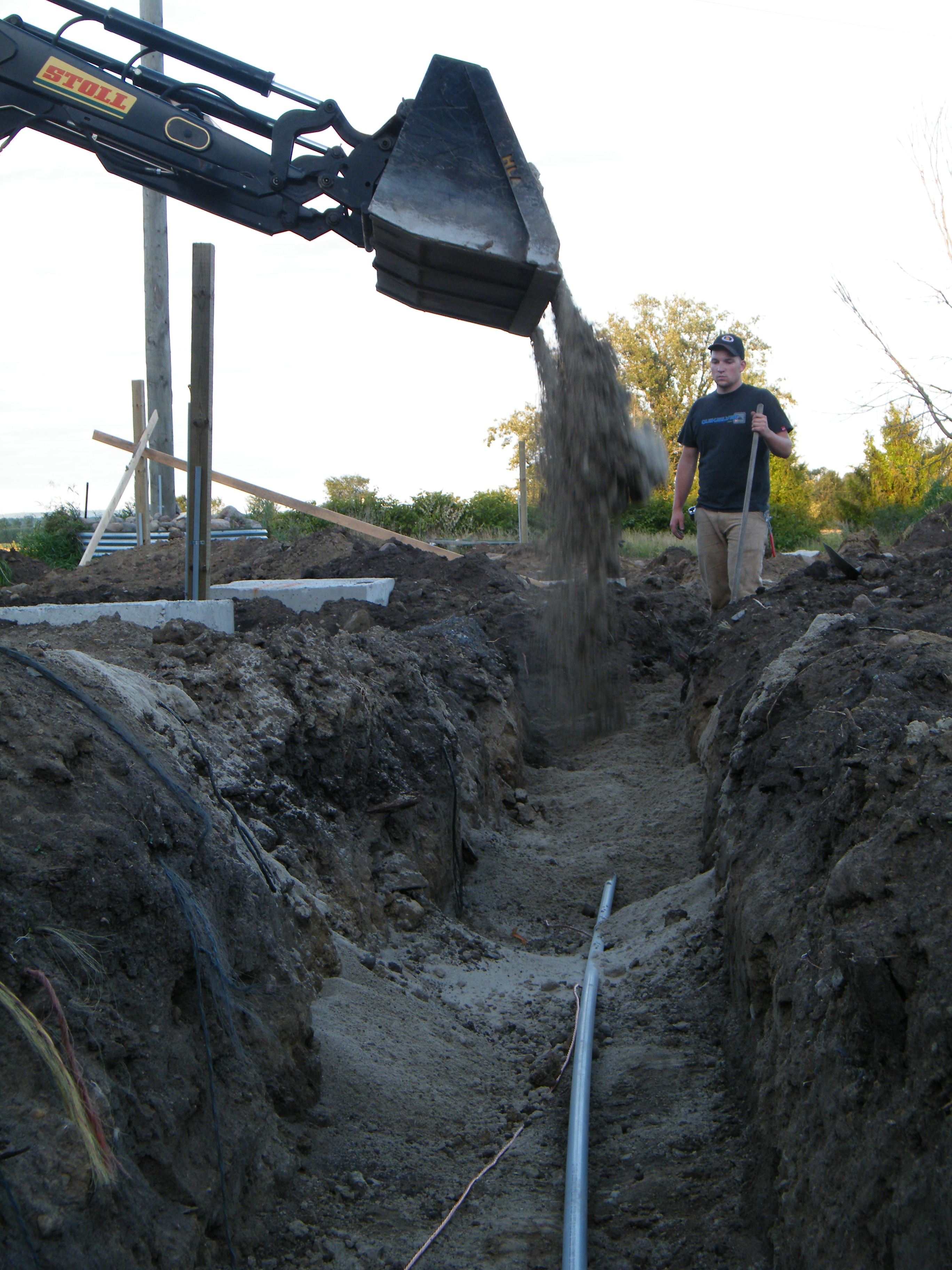
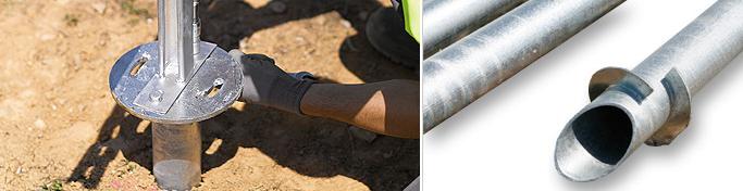 MecaSolar's MecaScrew earth screw.
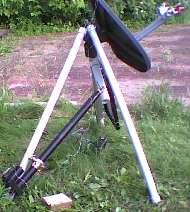
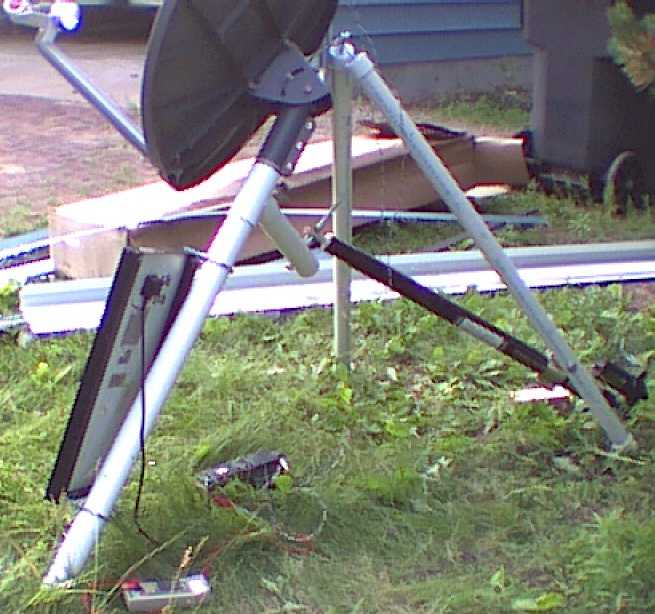
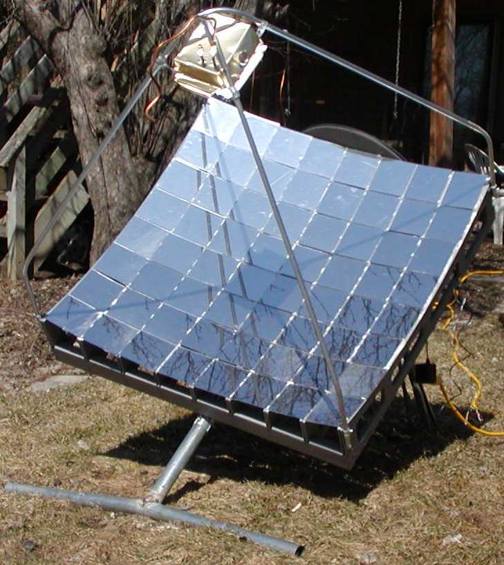
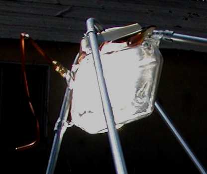
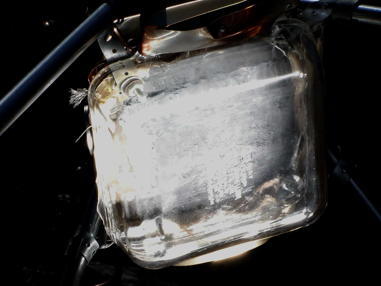
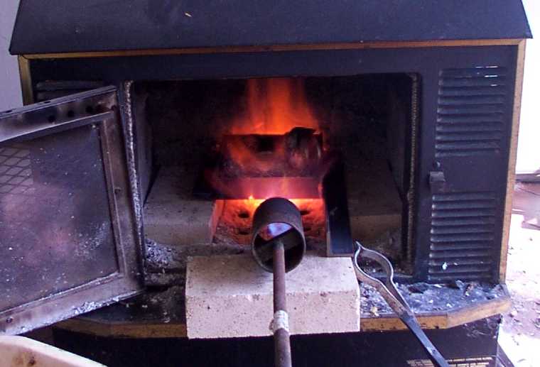
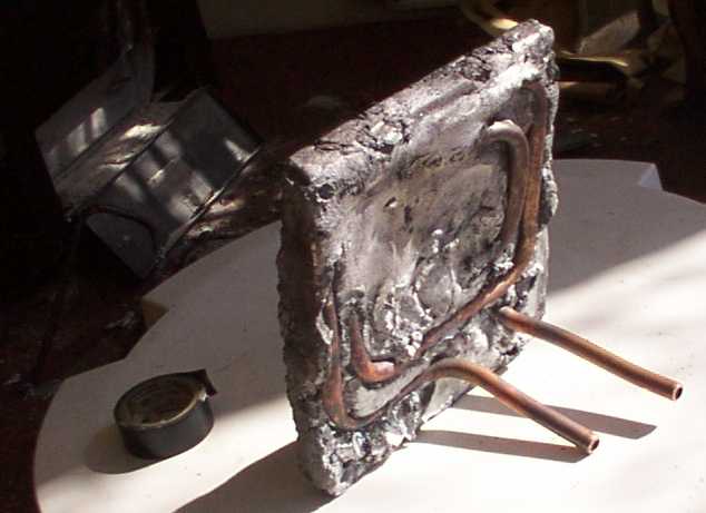
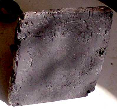
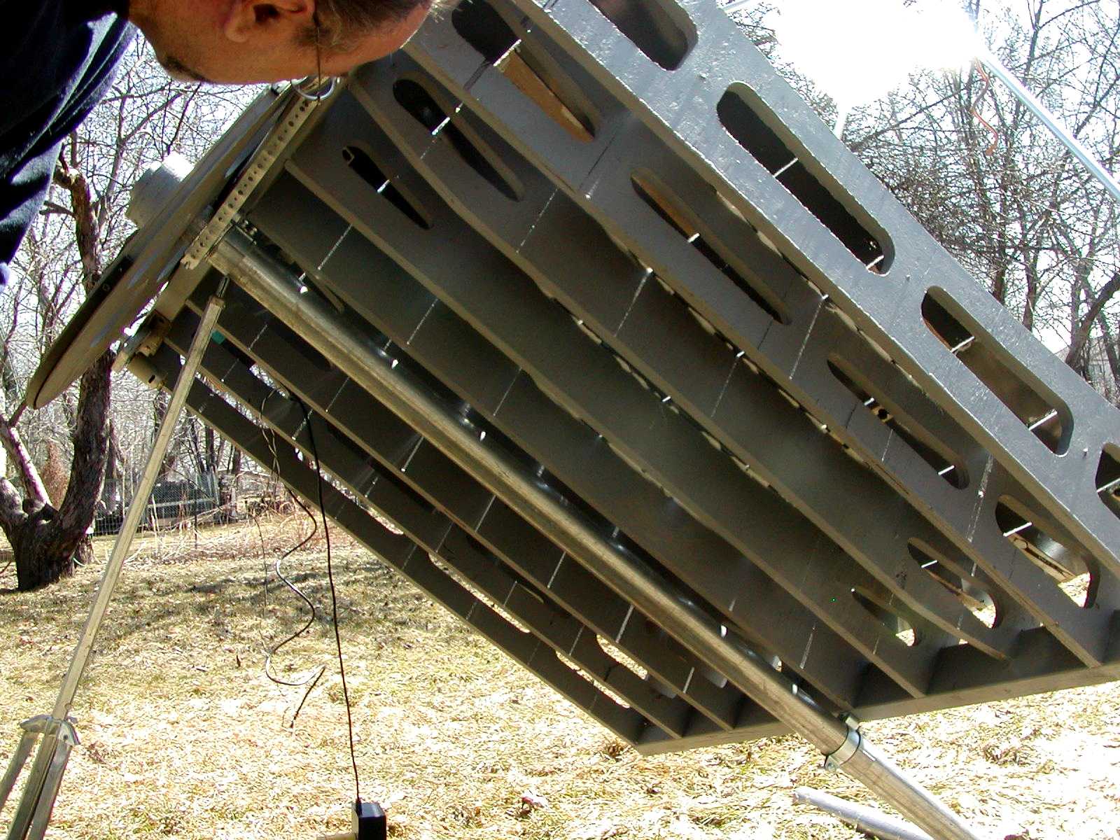
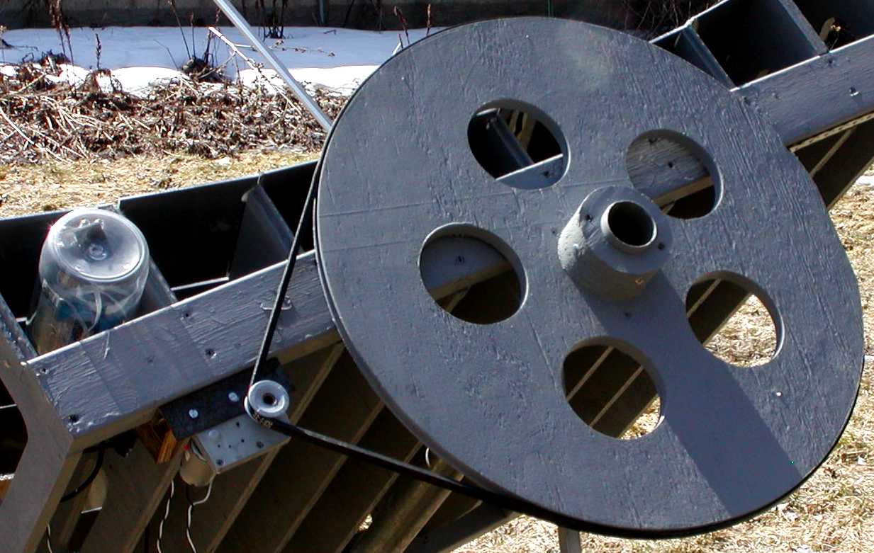
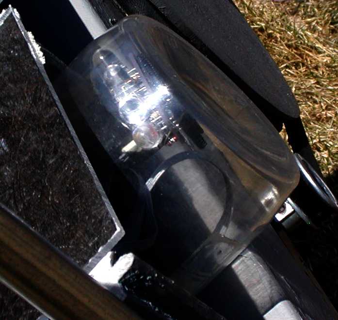
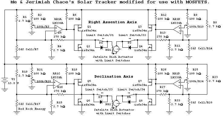 Chace1
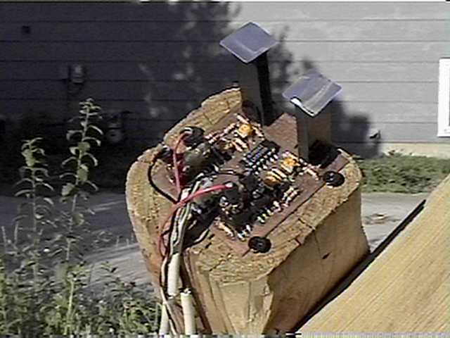

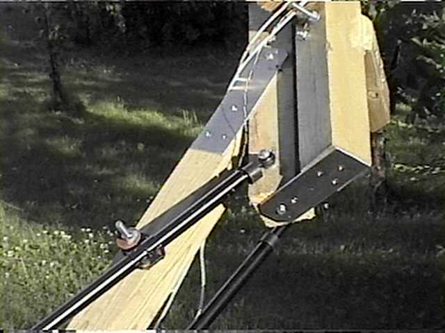

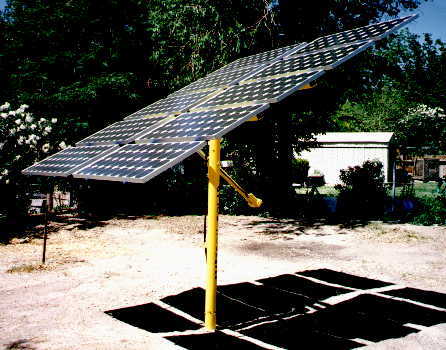 Brad's PV Solar Tracking Panel and Controller.