

Solar Tracker Operating instructions
These instructions are not completed yet. I am in the process of writing them.
Introduction:
The LED4 solar tracker is designed to track the sun by moving itself into a position where it is aligned with the sun. To accomplish this the tracker drives a linear actuator. Generally this actuator moves a solar collector with the tracker mounted to it.
Caution:
This board is made with high impedance circuits and is subject to static discharges which can damage the integrated circuits. When handling the circuit make sure you are well grounded. Your probably grounded by standing on the earth when working with the circuit. You can touch the edges of the board as these areas are all connected to the negative power terminal.
Mounting: 1. The easiest is to glue it along the bottom edge. Make sure the glue doesn't touch any of the circuit traces especially the timing capacitor area next to the 74AHCT14.
2. A small hole can be drilled in the corner of the board near the LM317L.
3. The best way is to solder a metal bracket in the corner near the LM317L. A small copper electrical ring lug works well for this.
The board is designed to have the circuitry mounted on the down side or closer to the earth, not upward toward the sky.
Weather Dome:
Connections:
If you want to remove a pin from the connector a small screw drive is inserted in the hole in the top to push the retaining clip down while pulling on the wire. The pin will come out. Make sure the retaining clip is slightly bent up before reinserting. Adjustments: If the tracker moves in the wrong direction reverse the leads on the motor.
I'm supplying the tracker without the eastward parking feature installed because I am not pleased with the sensitivity reduction the 22 megohm resister causes. I am searching for a 100 megohm resister supplier. This lack of a parking feature doesn't materially affect the operation of the tracker.
If the parking feature is needed we can talk about it later.
The tracker can be mounted in several ways.
A low cost weather dome to protect the circuit from the elements can be made with a 2 liter clear plastic soda pop bottle with the top cut off. The kind that has a black plastic foot. This foot is easily removed revealing a round bottom. I have uses a piece of 4"x4" wood with the corners rounded off. The plastic dome is snugly fitted over the wood.
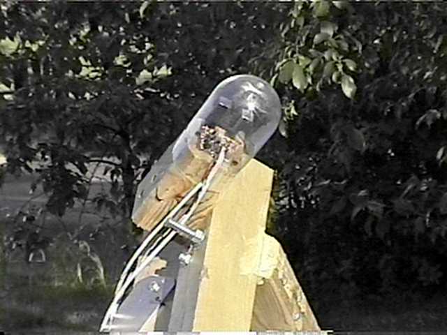
This is a picture of my old Chace tracker with a 2 liter weather dome.
A Molex connector is provided for all electrical connection. Pins 1 and 4 are for the power in connections and pins 2 and 3 go to the motor actuator. The pins are designed to use 22 gauge or smaller wire. However, I have used 20 gauge successfully. The wire doesn't need to be very large even when 10 amp motor startup currents are encountered because the currents are in a low 10% duty cycle.
The connector can only go on one way. The wedge is toward the PC board.
Once mounted the final adjustment is made by bending the outer LEDs to change the dead band. The closer the outer LEDs are parallel to the inner LEDs the less dead band one obtains.
LED4 Schematic