 Go back to Red Rock Energy.
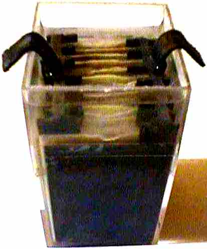
Peter <peterthinking@shaw.ca> is in the process of building this heat exchanger with plastic corrugated board called air core. Similar to some commercial units. Neat huh!
Hi Nick and Mark;
Nick Pine <nick_pine@verizon.net> wrote:
> Hi Duane,
> I'd be interested in learning more about how heat pipes work.
> Maybe you could post a short description of how to size them,
> how much to fill them, how to predict their performance, and
> how to make heat flow downhill...
Sorry nick. I am not aware of a method using heat pipes that will allow heat to flow down hill in any significant rate or distance.
Ever since you asked this question I have been wondering about things like the Servil refrigerators. They effectively pump fluids up hill with no moving parts. Of course they are optimised for refrigeration. Could something similar be made to work where hot liquids are moved and optimised for minimal delta Ts?
Greg Doty wrote:
> The Lorax <Lorax@pconline.com> wrote:
> > On Wed, 18 June 1997 Gary <GaryMay@aol.com> wrote:
> > > Does anyone know of a source for information on the design
> > > and construction of Freon based Solar Water Heaters?
> > > Any help would be greatly appreciated
> > They're in the process of phasing out the use of Freon
> > with the objective of stopping production of it all together.
> > I think you'd better look into a system that uses other chemicals.
> > The Lorax <Lorax@pconline.com>, St. Paul, Minnesota
> Thanks to DuPont, Freon is in fact being phased out of production.
> However, there are other chemicals with characteristics similar to
> Freon, some of which have even been approved by EPA, though they
> won't tell you what they are. A gas which is definitely NOT
> approved, BTW, is common ordinary propane used for cooking and
> heating. It works just fine in an auto air conditioner - just don't
> get caught with it, or get into an accident.
> Although I am not the original poster of the question, I also have
> similar interests, if anyone has info on the subject, relating to
> phase change generators somewhat popular back 20 - 30 years ago.
> The phase change generator, as a side product, could produce hot
> water.
Just for the record. Bill Dube' <bdube@boulder.nist.gov> said that;
Ordinary Propane is called R-290 &
Ordinary Butane is called R-600.
Bill and I have been using these gases in "Heat Pipes" to cool Electric Vehicle power controllers and other things. There are no moving parts, except for the fluid. These work very well. Butane pressure remains reasonably low and can be contained in reinforced plastic hose. The safety over pressure vent is directed to outside the car.
When asked what fluid is used in the heat pipes we say it's a refrigerant called R-290 or R-600 and leave it at that.
Besides, the amount of butane in a heat pipe is very small compared to the amount of gasoline in an ordinary car.
The gases tend to dissipate rather quickly and leave the vicinity of the car. Spilled liquid fuels tend to remain near the vehicle and are a hazard for a longer period of time.
I have developed a couple of tools that are useful in tapping fuel cylinders for use in experiments. If anyone is interested in these devices just email me and I can describe them in more detail so you can build your own.
I normally use the small propane torch cylinders for propane and the camping fuel canisters called GAZ for butane.
And another letter to Nick Pine <nick_pine@verizon.net> describing the details of a heat pipe I have made including the filling instructions.
Some thoughts on heat pipes I have made.
The main task of all thermal engineering is to move large quantities of heat from one location to another with as little temperature difference as possible.
There are a number of ways to do this task. Pumped liquid, moving gases, and transported solids. These techniques involve using motive power.
Convection, radiation and conduction are methods that use no motive power. However, these methods require considerable temperature differences to operate at high heat fluxes. Heat pipes are a special form of heat movement using phase change convection. Whereas normal convection doesn't employ phase changes as heat pipes do.
Heat pipes can be made in many forms and for many uses. I will describe two basic types.
The first type, a single tube type, is described well in these 2 web sites.
dehumidifier
This site has a good description of how heat pipes work. This site also has developed a thermally efficient dehumidifier that uses heat pipes:
http://heatpipe.com
enertron
thermacore
Heat pipes used to cool electronic components:
http://www.enertron-inc.com/html/reference_library.html
http://www.thermacore.com
Type 1 heat pipes are generally composed of a tube, closed at each end, that has a fluid in it. One end is called the "hot" end and the other the "cold" end. The pipe is well evacuated of air before the fluid is added. Usually there is a liquid fluid wick to help transport condensed fluid from the cold end back to the hot end.
Heat pipes transport heat introduced into the hot end to the cold end where it's extracted. The heat entering the hot end boils the liquid which turns to a vapor. The vapor expands in volume and travels to the cold end where it condenses to a liquid and gives up the heat.
In a perfect world there would be no temperature difference between the hot and cold ends no mater what the rate of heat transfer is. In reality there are physical limits to the rate of heat flow that can be transferred for a given temperature difference. The heat must conduct through several interfaces and each have delta Ts. This includes the metal thickness of the pipe walls at each end. Another temperature is the thermal path conducted through the liquid before it boils and after it condenses.
Another delta T is caused by pressure differences between the hot and cold ends. When the vapor travels to the cold end there is aerodynamic friction. This friction causes a pressure drop. The drop in pressure corresponds to a drop in temperature as referred to in the vapor temp vs. pressure tables for the fluid used.
There is another pressure/temperature drop caused by the transport of the liquid back to the hot end. The main reason for the wick is to prevent the high velocity of the vapor from interfering with the passage of the liquid by actually blowing it upward. The liquid is shielded in the wick from the gas and provides a return path.
This pressure drop can be minimized if the pressure of the vapor is made high. The velocity of the gas moving in the pipe is inversely proportional to the pressure. A fluid that operates at a high pressure will have less pressure drop even though the flow is the same. The friction is controlled by the Reynolds number which is exponential. Slower velocities are a good thing.
A really good performing heat pipe can have a delta T as low as 1C. Even 5C is probably better than anything using ordinary conduction techniques.
Bill Dube' <bdube@boulder.nist.gov> described a very interesting variation of the type 1 heat pipe that he worked with while in college. This tube was capable of acting as a temperature controller for photochemical baths. The source of the "coolth" was an Ice bath at the top. Ideally they would not be misible and had widely differing boiling points. This pipe purposely had 2 working fluids. This pipe had a resivoir at the top to contain the second vapor. This application could maintain the baths at any precise temperatures and all with no mechanical moving parts.
One use for heat pipes is a device called a thermal diode. If a solar collector is positioned below it's storage a heat pipe will transfer heat upward to the storage but not the other way. Neat huh.
Type 2, 2 pipe, heat pipes help reduce the effects of the counter flowing liquid and vapor.
In general 2 pipe heat pipes don't require wicks. The main pipe, generally larger, is for transporting the vapor to the cold end. A smaller return pipe brings the condensed liquid back to the hot end.
The type 2 should be plumbed so the top of the hot end connects to the top end of the cold end. Also the bottom of the cold end connects to the bottom of the hot end. Sometimes it's helpful if the liquid return line is insulated from the surrounding heat source otherwise boiling may occur and interfere with the passage of the liquid.
2 pipe heat pipes can be made using flexible tubing since no wick is used. I have made these using butane and nylon reinforced PVC plastic tubing. The cold end was made using copper fin tubing and the hot end a machined aluminium plate.
Generally heat pipes work best with the hot end at the bottom and the cold end at the top. The liquid is returned using gravity.
Heat pipes can be made that operate horizontally or even with the hot side on the top. These must depend on the capillary action of the liquid in the wick to to return the liquid to the hot end. Needles to say, these have severely reduced performance as gravity exerts a powerful force. The main limitation is the vertical distance the wick can pull the liquid up. Usually these heat pipes are less than a few inches high or are used where there is no gravity, such as in space.
Type 2 Heat pipes can be controlled using valves. Under the cold end and above the hot end is a reservoir sized large enough to collect all the liquid. The valve is used to admit liquid to the hot end when heat transfer is needed.
Water is often the liquid of choice as it has a high latent heat of vaporization, a desirable trait. One problem with water is that the vapor pressure is less than 1 atmosphere at room temperature.
Other fluids are refrigerant gases and fuel gases.
Butane, or pentane if you can find it, is preferred when using flexible lines as the pressures are lower.
Propane is preferred when solid lines are used as the pressures are higher.
Filling a heat pipe using the pressurized gases is easier than with water or other room temperature liquids as evacuation is not needed. I use a technique where I over fill the pipe and then carefully vent the gas. The venting expels the entrapped air and other dissolved gases. This venting process should not be used with Freons or other green house gases because it's against the law, besides it's expensive. The fuel gases are very cheap.
I have done some experiments using butane from a commercial product called GAZ that is obtained from camping equipment stores. it's about 95% butane and 5% propane. My experimental heat pipes, ( lets call them coffee coolers ), appeared to be cooler at the top then they should have been. Remember that heat pipes strive to be isothermal devices. There should not be much temperature difference between different regions of the pipe. After careful analysis I have determined that the propane portion was separating out, a kind of gaseous distillation, at the top and not condensing. To remove this bit of propane I run the pipe fairly hot and just tap the Schrader fill valve. This vents tiny amounts of the propane until only the butane is left. Now the pipe runs at maximum performance.
This technique works for removing air and other trace high volatile dissolved gases. Of course, the fill valve should be at the top where these gases accumulate.
The correct fluid fill is just enough to keep the hot end filled with liquid at the hottest expected operating temperature. The amount of fluid can be determined either by weight or a sight gauge. The refrigeration industry has solderable sight glasses. I like these because you can see the operation of the moving fluids. This is very educational. The flexible tubing used with butane are semi clear and work nicely as sight gauges.
Remember, as the temperature increases a higher percentage of the liquid is changed into vapor at higher pressures. If the liquid level is too low then the thermal performance will suffer and may even stop operating altogether.
I have a couple of tools that I use to fill my heat pipes. I use valves similar to those used for filling tires. The Schrader valves used for refrigeration gases are physically identical to those used for tires with the exception that they can take several hundred PSI of pressure. I buy mine at automotive stores. I ask for the ones used for air conditioning fittings.
I use brass threaded fittings to hold the valves. These are used to introduce air into pressurized water tanks. I get these from well stocked hardware stores. The fitting mates to the type of cap used on tires.
I make two types of filling adapter, one for the standard propane tank and another for camping GAZ canisters. They are both based on the machined brass tire valve caps. They are both built in a similar manner.
Brass tire valve cap drilled to the size of brass hobby tubing and soldered in place.
------------------                   -----------------------
v^v^v^v^v^v^v^\   \                 | Canister fitting
 Tire Thread  |    ------------     |
v^v^v^v^v^v^| |                |    |   --- O ring
------------   ----------------      ---( )----------
              ----------------------------------     \
             | brass tubing tapered, polished   \     ------
      --      -----------------------------------   --
     |  |  --                                  --  |  |
-----   | |  |--------------------------------|  | |   -----
Schrader| |   brass plunger used to open valves  | |Canister
-----   | |  |--------------------------------|  | |   -----
Valve|  |  --                                  --  |  |Valve
      --      -----------------------------------   --
             |  and soldered to the fitting     /     ------
Tire fitting  ----------------------------------     /
------------   ----------------      ---( )----------
^v^v^v^v^v^v| |                |    |   ---
Tire Thread   |    ------------     |
^v^v^v^v^v^v^v/   /                 |
------------------                   -----------------------
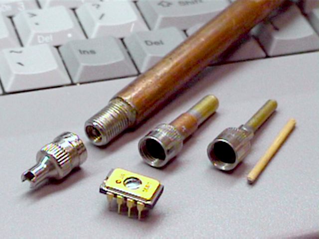
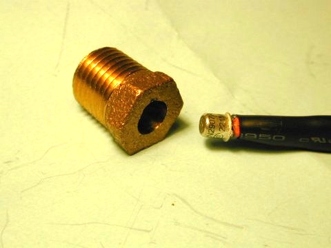
A common tire valve cap. The fill valve end of a 1/4" heat pipe.
Two tappers. Propane on the left, GAZ on the right.
A wooden toothpick plunger at far right.
An 8 pin PIC microprocessor for size comparison.
I build Propane and GAZ canister tappers by using brass hobby tubing that fits into the canister orifice.
Brass tubing diameter for Propane Cylinder = .188", 3/16"
Brass tubing diameter for GAZ Canister     = .125", 1/8"
This can be obtained at a hobby supply store. The internal valve to release the butane needs to be pushed in by the end of the brass plunger, or wood as in the picture. The GAZ canister has an "O" ring to seal to the tubing. It's best to taper and polish the sharp end of the tubing to protect this "O" ring.
The brass plunger is used to open both valves simultaneously to facilitate the liquid transfer. Make sure it's just long enough to open both valves. It should also be short enough to allow the mating to the "O" ring seals before the valves are opened otherwise gas will be needlessly vented. Sever frost bite can occur if liquid fuel is vented on your hands, not to mention the possibility of a fire.
Working with compressed liquid fuel gases can be hazardous. The liquid is becomes very cold when vented. This can cause severe frost bite. The gases are also combustable. They can cause a fire or even an explosion. Please use caution when performing these operations. It is best to do the work outside. A garage with the door completely open is acceptable.
Keep a fire extinguisher handy. I also keep a pail of warm water to plung my hands in to limit the posibility of deep frost bite.
I have transferred gas from the canister to the heat pipe and back easily. The basic trick is to slightly heat the source in lukewarm water. Then connect the two together with the warm source on top and the cooler one on the bottom. Liquid gas will be forced to run out of the upper into the lower with the aid of the pressure differential caused by the heat.
A second and more important reason to heat the source canister is to thermally expand the liquid propane. If the receiving container is accidently completely filled with warm liquid and subsequently cooled to room temperature the pressure won't explode the container. Once it's filled vent a small amount of gas to make sure there is at least some vapor space at the top. Of course a heat pipe is normally mostly filled with vapor with a smaller volume of liquid.
And this is the BIG CAUTION.
If, however, you transferred cold liquid and completely filled the container the pressure would get very high when later the cold liquid expands when heated to room temperature. This is a DANGEROUS condition! The Schrader valve will probably fail and vent all the gas uncontrollably. Again, make sure to vent some gas when done just to make sure.
Good luck!
 Data Logger.
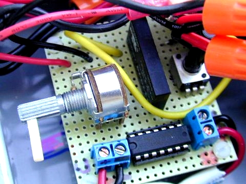
This site describes a temperature logging system. This system is the first phase of a Solar Heating Controller he's designing. Here you will find the PIC (16C84, DS1820) firmware source, hardware schematic, and logging / monitoring applications.
 The Copper Page
A service of the worldwide copper and brass industries.
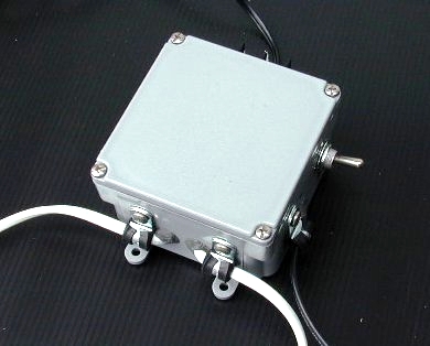
Differential Temperature Controller Schematics.
Based on Diode temperature sensors, Thermocouples, and Thermistors.
Specifications:
LM324,
LT1006C,
2N2907A
Walter Pearson built a working Diode sensor based Differential Temperature Controller. He drives a water pump in a solar thermal water heating application.
The LM324 in the circuit easily drives the 3.5A 24VDC solid state relay, CN024D05.
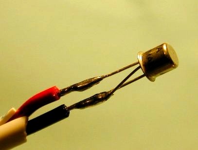
The 2N2907A is a metal cased PNP transistor which is particularly well suited for use as a temperature sensor as the metal case has good thermal connection to the silicon inside. The metal case is hermetically sealed and connected to the collector.
Nice job Walter!!
See Walter's Tripod Polar Axis Tracking Mount.
This DIFFerential AMPlifier can be used to read current shunts.
The ressistors should be closely matched to have good common mode rejection.
Specifications:
LM324
While I have tested this circuit there may need to be some component changes for your specific application. I use it to sense the indicator LED on my LED3X solar trackers.
Use a small lens, about 1" in diameter, with a short focal length. About 1" as tested using the sun. Then mount the lense about 2" from the sensor and about 2" from the pulsed light source. Mount in a tube to eliminate unwanted light from entering.
Use an LED sensor of the same color as the indicator LED one is sensing.
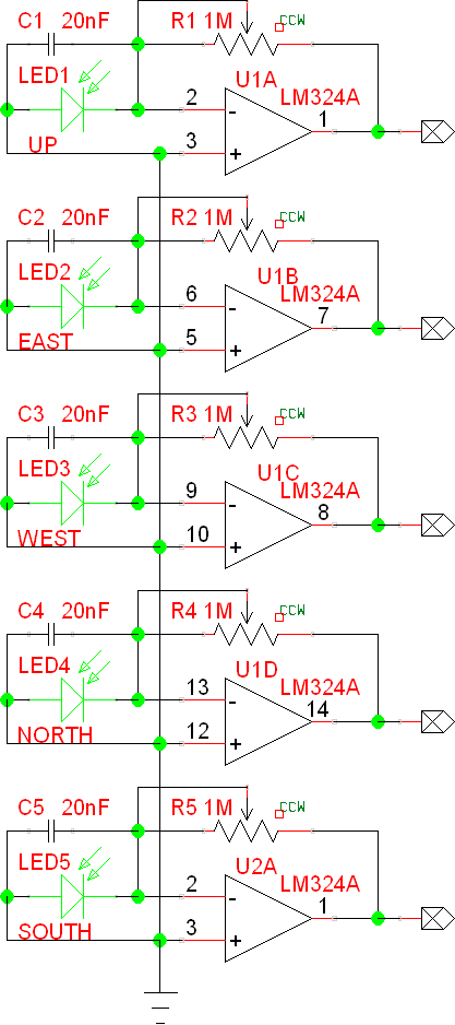
The LED pulls current from the node into the Cathode attempting to bring the voltage negative. The OpAmp counters this by bringing the output voltage high enough to develop just enough current, equal to the LED photo current, across the feedback resistor. The output voltage is directly proportional to the photo current.
For a given light intensity the photo current is dependent on the cosine of the angle of light entering normal to the sensor. Strait in, 0° = 100% or 90° = 0%. By measuring the 5 outputs the direction in AZimuth and ALTitude of the brightest average direction relative to the stationary can be determined.
Specifications:
LM324
Over the years I have made a number of Broken Filament Anemometers based on this general schematic. These are usually called "Hot Wire Anemometers".
Specifications:
LM324
The lamp I like is a 14V 80mA lamp but just about any low voltage low current type can be used. Carefully crack the glass in a vice to expose the filament. The filament is very fragile so be careful.
The way it works is by heating the filament. The hotter the better but not so hot that it burns out. The circuit tries to maintain a constant temperature. The faster the air blows over the filament more power is needed to maintain the temperature. The current meter reads this power and is fairly proportional to the air speed.
The anemometer can be calibrated by hanging it out a car window. Since the measurement is based on filament temperatures higher ambient temperature will cause the measurements to read low. This error is minimized by using higher filament temperatures. In general try to measure velocities at ambient temperature.
When measuring air velocities on solar heating panels measure at the cooler inlet side.
Cool huh!
Here are some others:
Thermal anemometers
Amateur design report by Johan Liljencrants
"Electronic Design" Design Briefs, Oct 3rd, 1994
Hot-Wire anemometer
"Measuring Circuits" by Rudolf F. Graf
This circuit has a linearizing circuit.
Direct Temperature Sensors based on the venerable LM34.
LM34
The LM34 reads directly onto a voltmeter at 10mV/degree F.
The range is +5F to +300F.
There is a distinct advantage to the LM34 as it starts running at a temperature below the freezing point of water, (-15C).
LM35
The LM35 reads directly onto a voltmeter at 10mV/degree C.
The range is +2C to +150C.
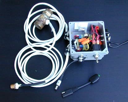
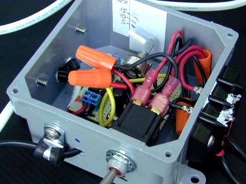
A simple low powered inverter.
Conventional DC power switches are generally quite expensive compared to AC power switches when uses in alternative energy applications, especially when switches are installed in house wiring boxes and switching heavy DC currents.
AC power switches are not suitable in DC applications because they don't have DC arc quenching features. Once a DC arc is started it can be very destructive. If the arc is not started in the first place these switches can carry the full current rating of the switch. I designed an electronic circuit that prevents arcs from starting which can be added to conventional AC power switches.
This circuit operates by selectively shunting a pair of switch contacts for a short period of time after it is opened. In this case I used a standard 3-way switch, sometimes called a Single Pole Double Throw, SPDT. However, it is not used in the 3-way mode. The second contact is used to shut the MOSFET off after guaranteeing the main contacts are fully open.
Please, select "Snap Action" or "Toggle" switch types, not the quiet or silent types. The snap action switches quickly move from one contact to the other. The advantage is there will be less power dissipated in the MOSFET.
The MOSFET doesn't need a heat sink in this application. The MOSFET conducts high current for only an instant until the switch shorts it out and significantly reducing the current. The switch conducts nearly all of the current.
When the switch is opened the MOSFET takes over for a while until the contacts are completely open. No arc can occur across the contacts because the voltage is very low and there is little current to establish the arc. The MOSFET then opens up when the second switch contact is made. Since the MOSFET conducts high current for only a short time no heat sink is needed. OK, you can't switch it to often, but normal switch use is well within thermal constraints.
I'm specifying a strong transistor in the schematic that will cover most applications. This is a $2 transistor. I have done my testing with a much smaller transistor, MTD5P06V1, and things have worked well at 15 amps. The IRF5210 is getting hard to find. I now would use the IRFP9140N.
This circuit was designed for 12V or 24V systems, this implies a voltage range of 5V to 44V. I have tested it throughout this range. I think it can be used in a 48V system but I haven't tried this yet.
Tim Keating and daestrom correctly pointed out that some switches could cause the MOSFET to over heat if the switch was somehow set to a center position where the main contact wasn't made. For this reason I added a Raychem RXEF160 PolySwitch resettable fuse. This PolySwitch is epoxied to the surface of the MOSFET. It only costs about $0.46 each.
This circuit works with "Quiet Action" switches, the ones without "snap action" operation. However, I wouldn't use them.
In my response to daestrom I suggested that "sparks" are desirable when closing contacts to keep the contacts clean when using AC switches in low voltage DC circuits. While the 1uF capacitor does hold off the MOSFET about 35mS, in some circumstances this may not assure the main contact has it's closure "spark". I added the NPN transistor circuit to guarantee this small spark will occur. It delays the MOSFET turn ON timing until the main switch contact has closed and is delivering power to the load.
Have fun!
BTW, does anyone want me to make a small PC board for this?
Basic driver program
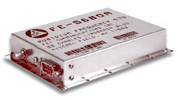
I needed a high accuracy high stability frequency reference for a NASA Space Elevator Contest project. I chose the Frequency Electronics FE-5680A rubidium reference. The cool thing about the FE-5680A opt. 02 as it has a DDS, Direct Digital Synthesis oscillator. This means it has a programmable frequency output of 0Hz to 20MHz with a resolution of about .01Hz. The accuracy is about 1 part in 10^9 or better.
I wrote this program to conveniently operate the FE-5680A. The program is written in BASIC. Actually Borland's Power Basic as I needed to use COM4: for my Windows XP computer. You could run in native BASIC if you have COM1: or COM2:.
I included the program in:
1. Native BASIC form
2. A compiled .exe executable
3. A config file for selecting the com port and a preset frequency.
4. Some notes in a .txt file.
I made some modifications to the FE-5680A described in these documents.
FE-5680A precise reference frequency rev-1_0
FE-5680A Rubidium 10MHz Reference
Good luck.
This web site is devoted to the exciting activity of Amateur Experimental Rocketry
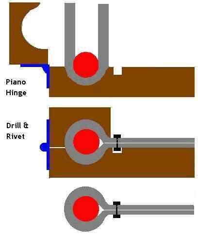
Wrapping Jig
Home made solar collector
<J. Ersing> made this jig to wrap aluminum sheet around copper tubing. I posted his pictures an instructions here:
I have attached a JPG of the jig that I made. On the only test piece that I made I used 1/2 inch dia copper and aluminum flashing and the length of the jig was 24 inches. I riveted every two inches. However, I think that the rivets could be spaced about every four to six inches depending on absorber material used. Aluminum would have more tension than copper. The bond was very strong. I couldn't pull it apart. I suppose that to increase the mating surfaces one could include a brushed on layer of thermally conductive grease.
Required materials:
One each 2 x 4 x 96 inches
One each 5/8th diameter round nose (core box) router bit
One 48 inch piano hinge or three or four heavy door hinges
The illustration is pretty much self explanatory to any average woodworker / hobbyist / builder / tinkerer.
Instructions:
After placing material into the jig (top pic), close the upper part of the jig and secure with a few clamps on the hinge side. Drill and rivet.
Let me know where you post it at redrok. I have visited your site many times over the since six months since I first became interested in solar thermal. I have found it very educational. Consider this my return contribution. I only require that you do not make this a commercial item for sale in any way (sell plans or sell a finished clamping jig) Consider this my small contribution to the big picture for all the other DIY and enthusiasts out there in the world.
Regards,
J. Ersing
Thanks J.
beadingjig1
Beading Jig
For use with sub-floor heating.
I've been thinking of a different method for use with floor heating. This method needs a deep bead rolled down the center. The beading press die should make the bead with the depth about 3/4 of the tubing outside diameter. Also an angular deflection should be pressed in at the same time.
This press die should be able to bead aluminium sheets about 1 foot long and about 16 inches wide, to be optimised later. The sheet bead is chalked with RTV and stapled in place. The V bend is reversed to somewhat wrap around the tubing.
And here is another bending jug:
This is by Gary on his Build it Solar web site.
Make the tool fairly large, maybe 2 foot square. The larger the size the less fringing effects will affect the accuracy.
The aluminum plates tend to spread the heat and average variations in the wall. I would use thermocouple temperature sensors although I have used diode sensors which can be cheaper. Make the plates quite a bit smaller than the insulation sheet.
The reference insulation should be high quality. I use Polyisocyanurate foam. The R value for mine is 5.30 (ft^2 F hr)/(BTU) for 1" foam.
http://en.wikipedia.org/wiki/Polyisocyanurate
http://en.wikipedia.org/wiki/R-value_%28insulation%29
Make 3 temperature measurements: Standard Microsoft Basic program (BASICA or GW-BASIC).
10 Tin   = 65   :REM inside plate temperature in degrees F
20 Tmid  = 60   :REM middle plate temperature in degrees F
30 Tout  = 37   :REM Outside wall temperature in degrees F
40 Rref  = 5.30 :REM R-value of the reference in (ft^2 F hr)/(BTU)
50 Rwall = (Tmid - Tout) / (Tin - Tmid) * Rref
60 PRINT "R-factor for the wall = " ; Rwall ; "(ft^2 F hr)/(BTU)"
99 END
This particular set of readings shows a wall R-Factor of 24.38(ft^2 F hr)/(BTU).
This is based on a Reference R-Factor of 5.30(ft^2 F hr)/(BTU).