 πΩθ©±°²³µ¼½¾÷ø
Last modified on 20180222
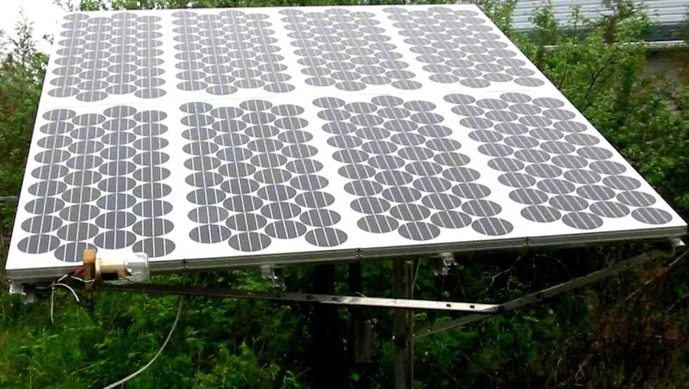
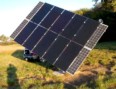
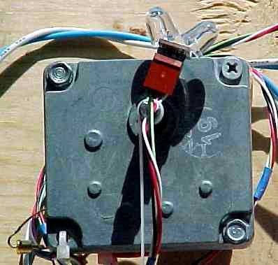
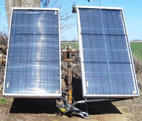
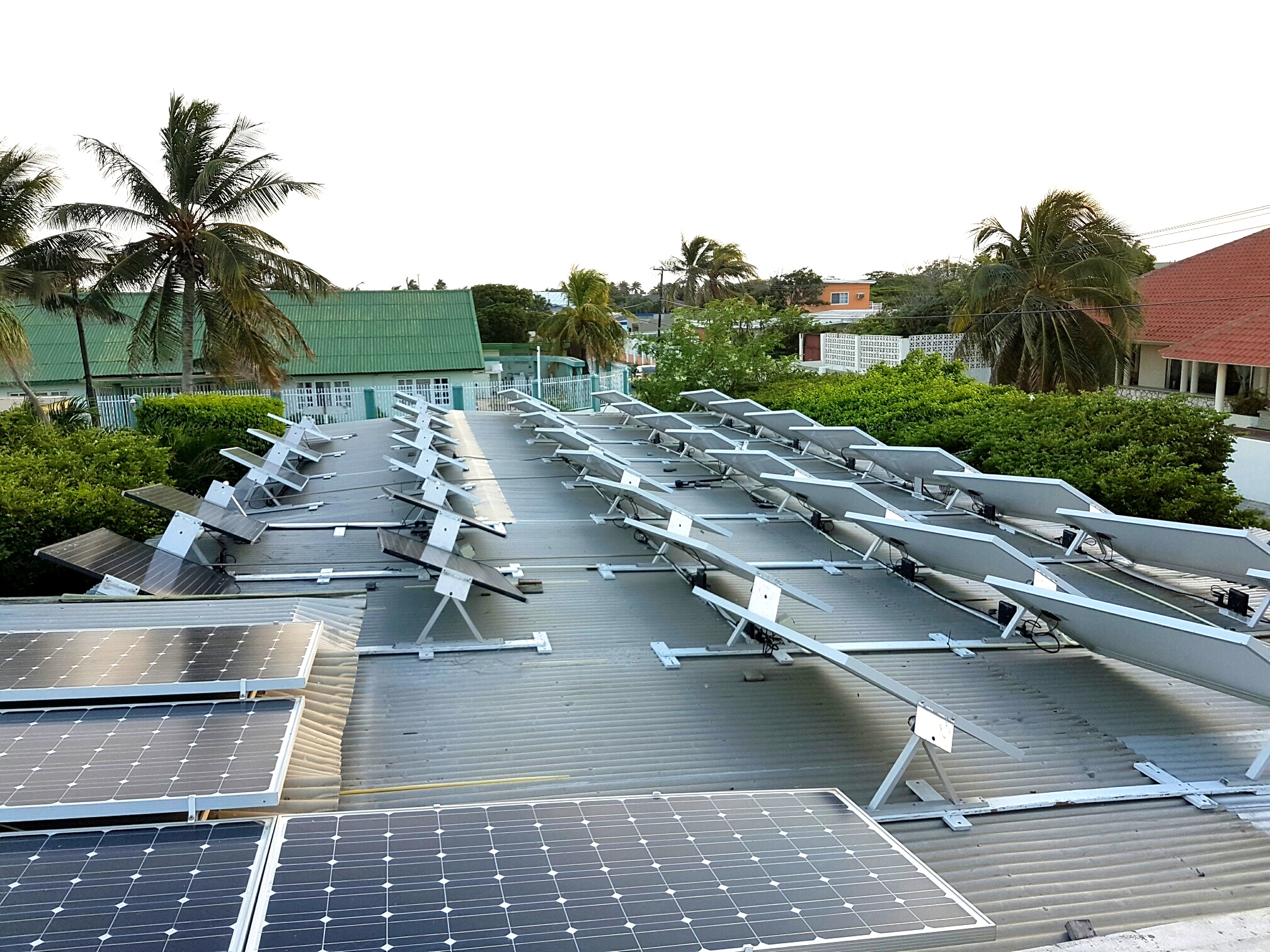
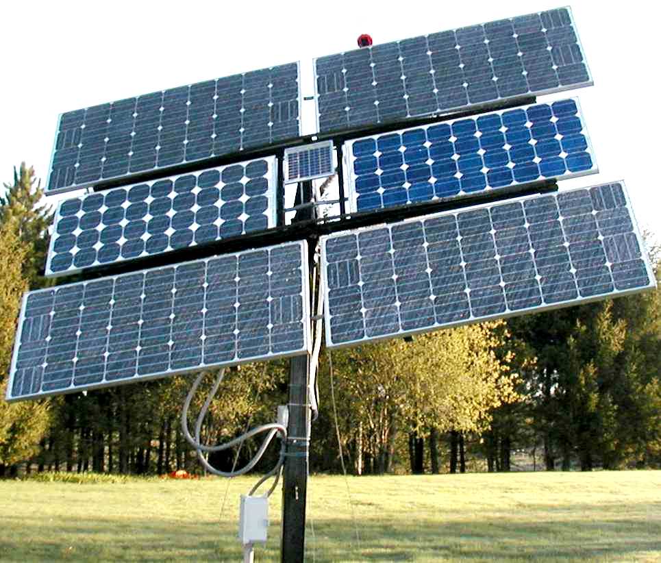
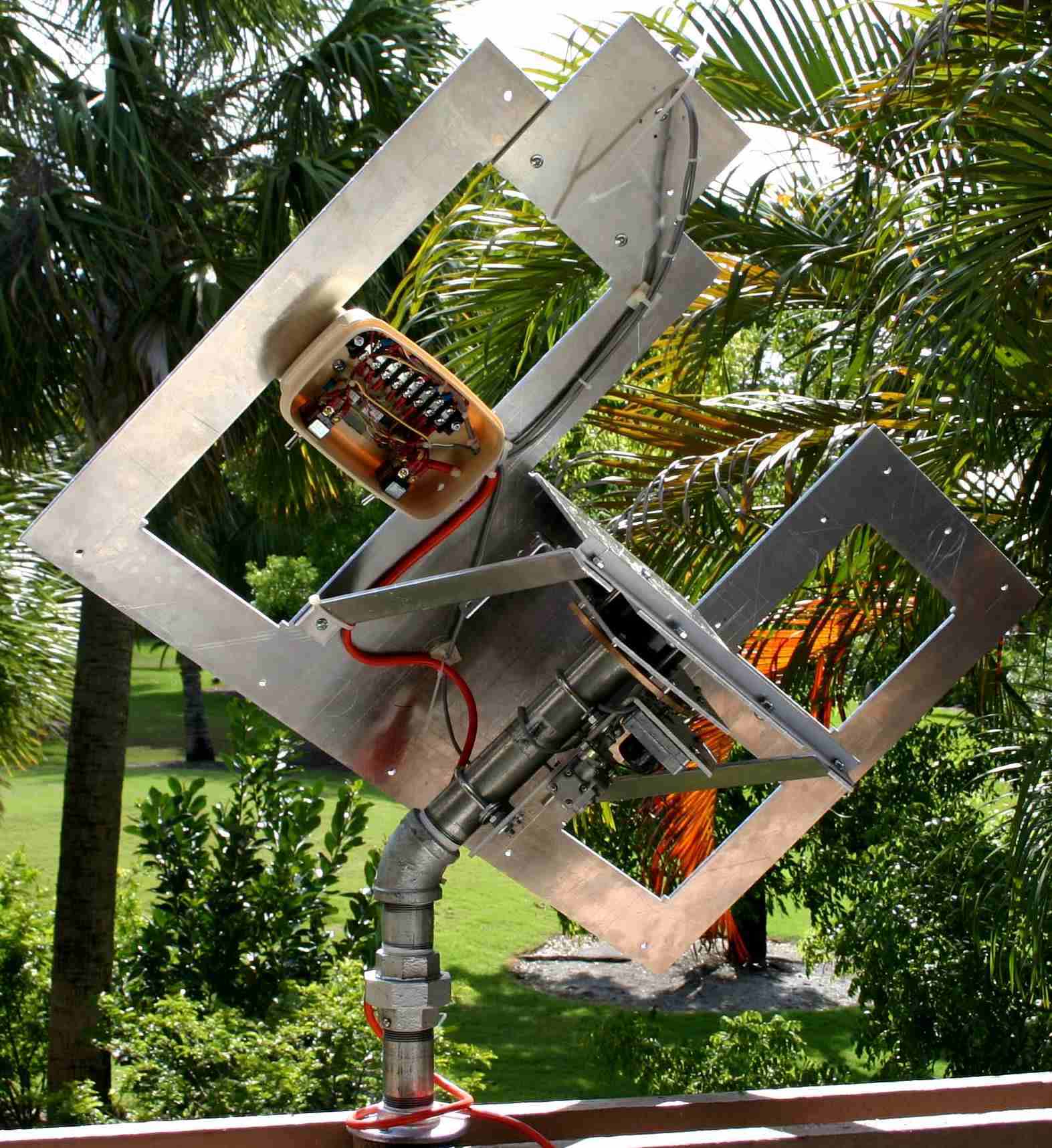
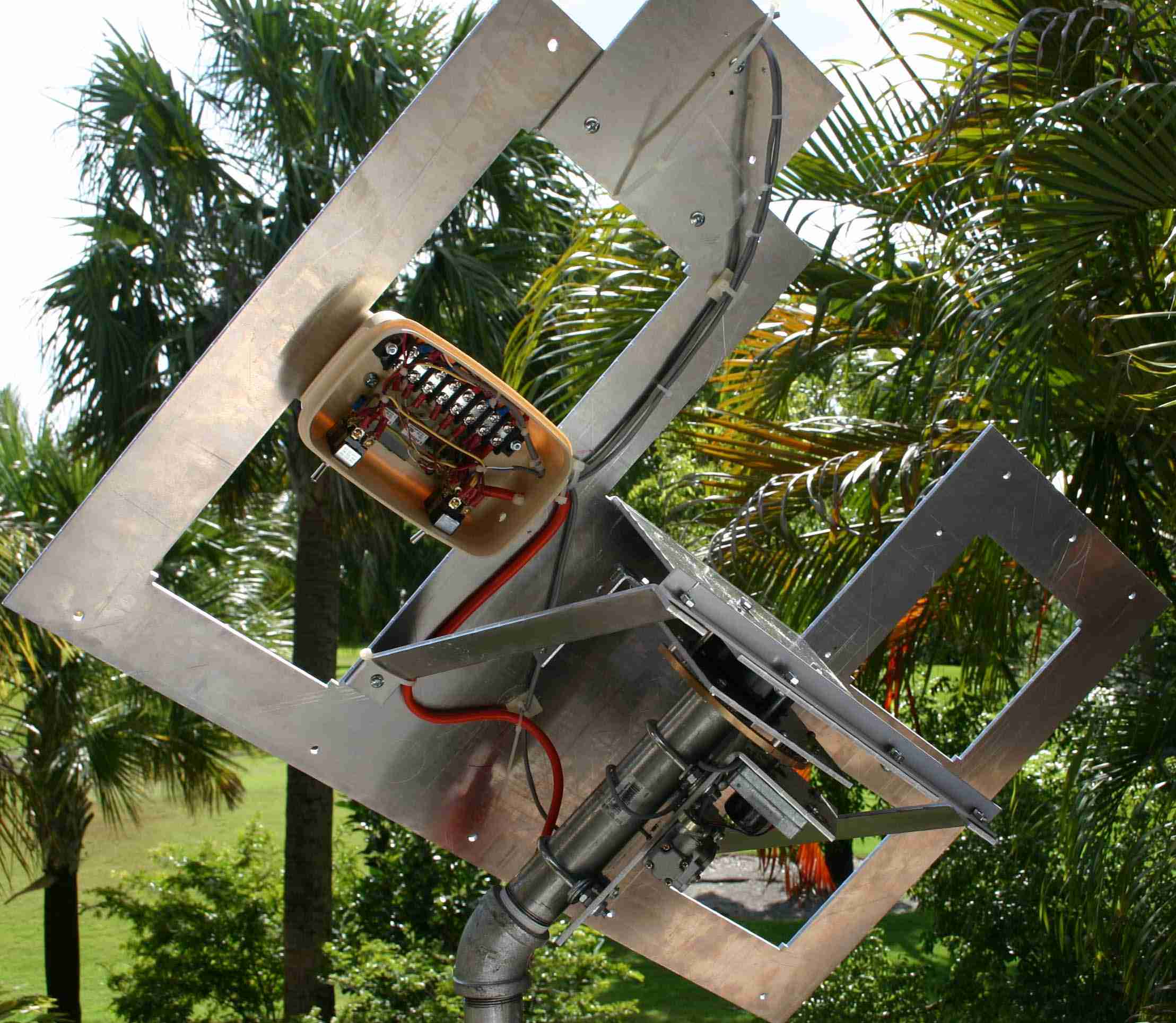
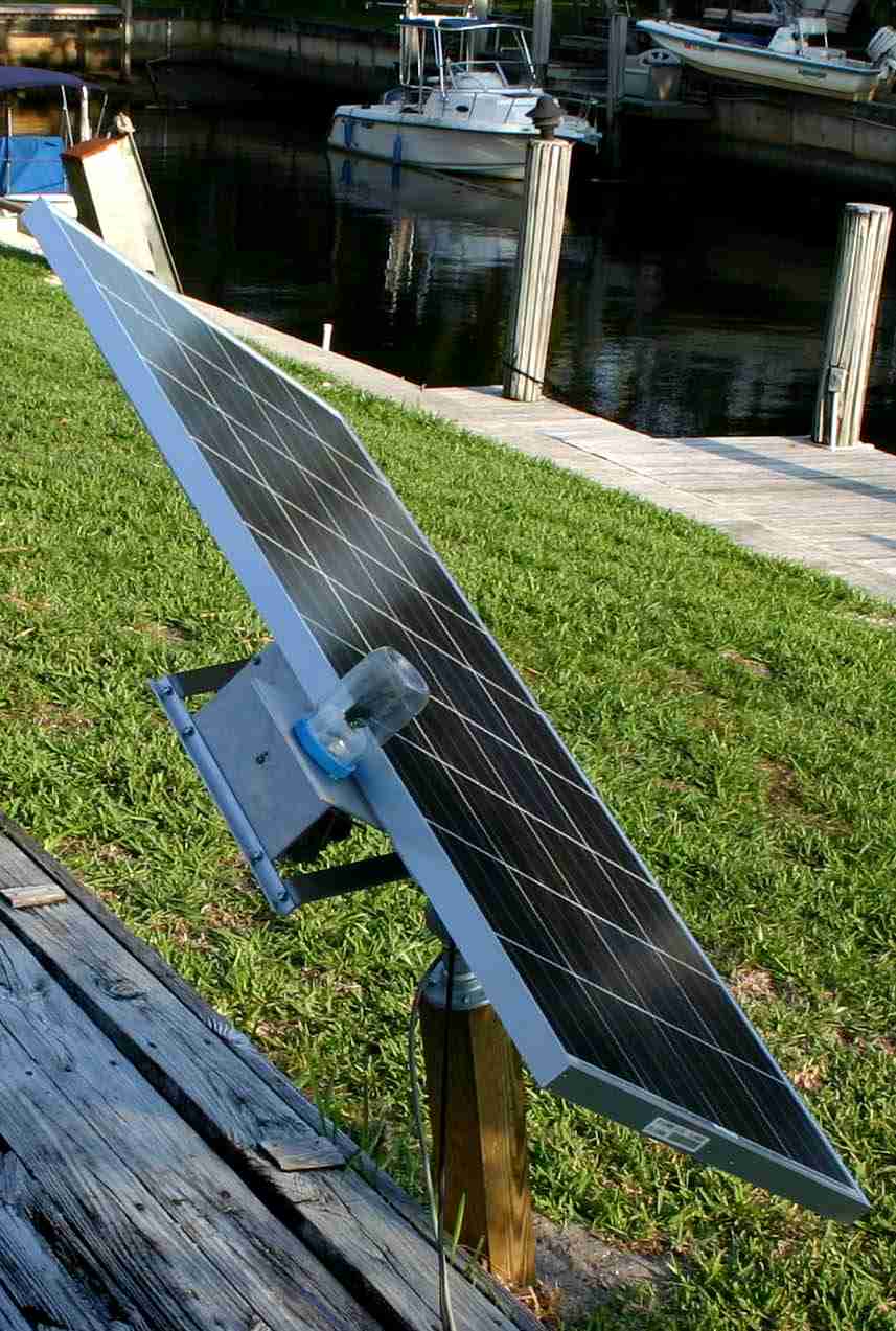
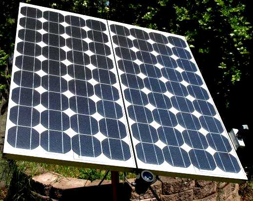
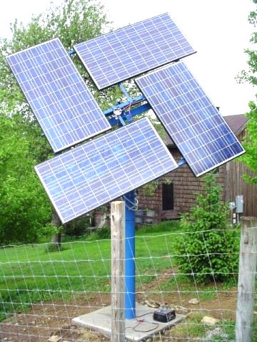
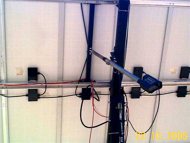
 West Front. |
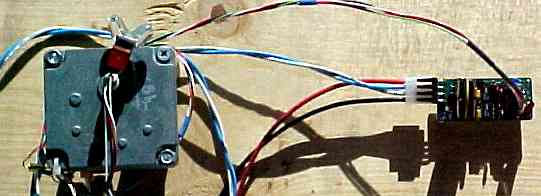
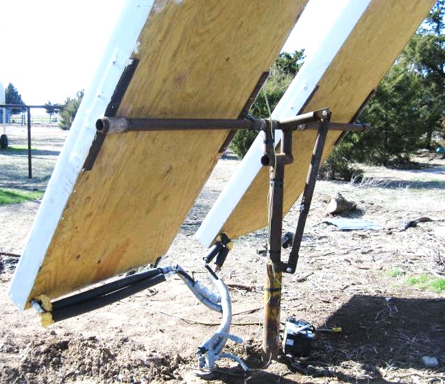
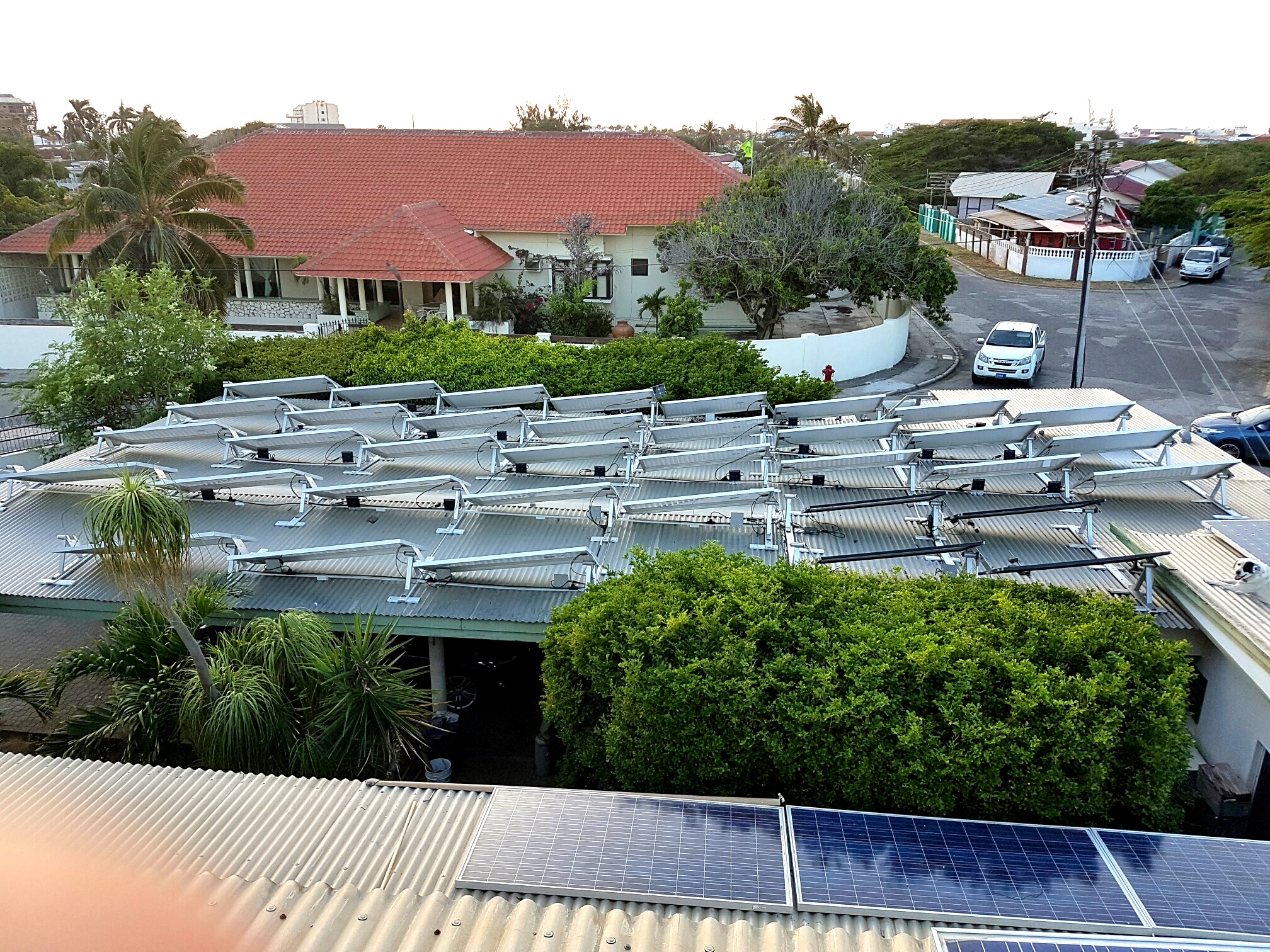
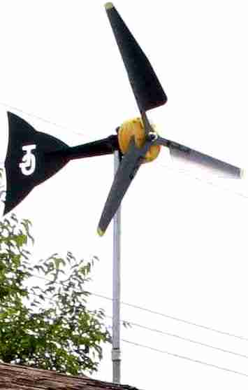
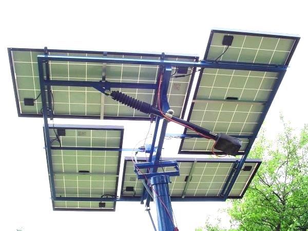
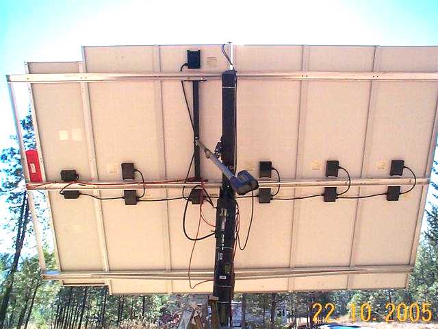
 East Rear. |
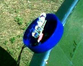
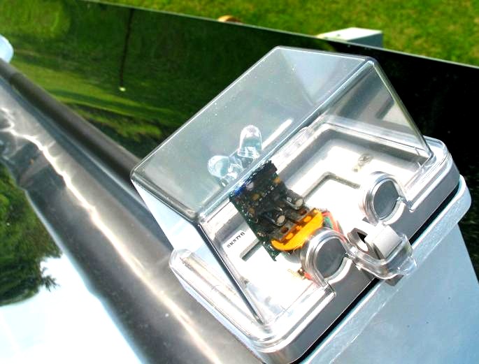
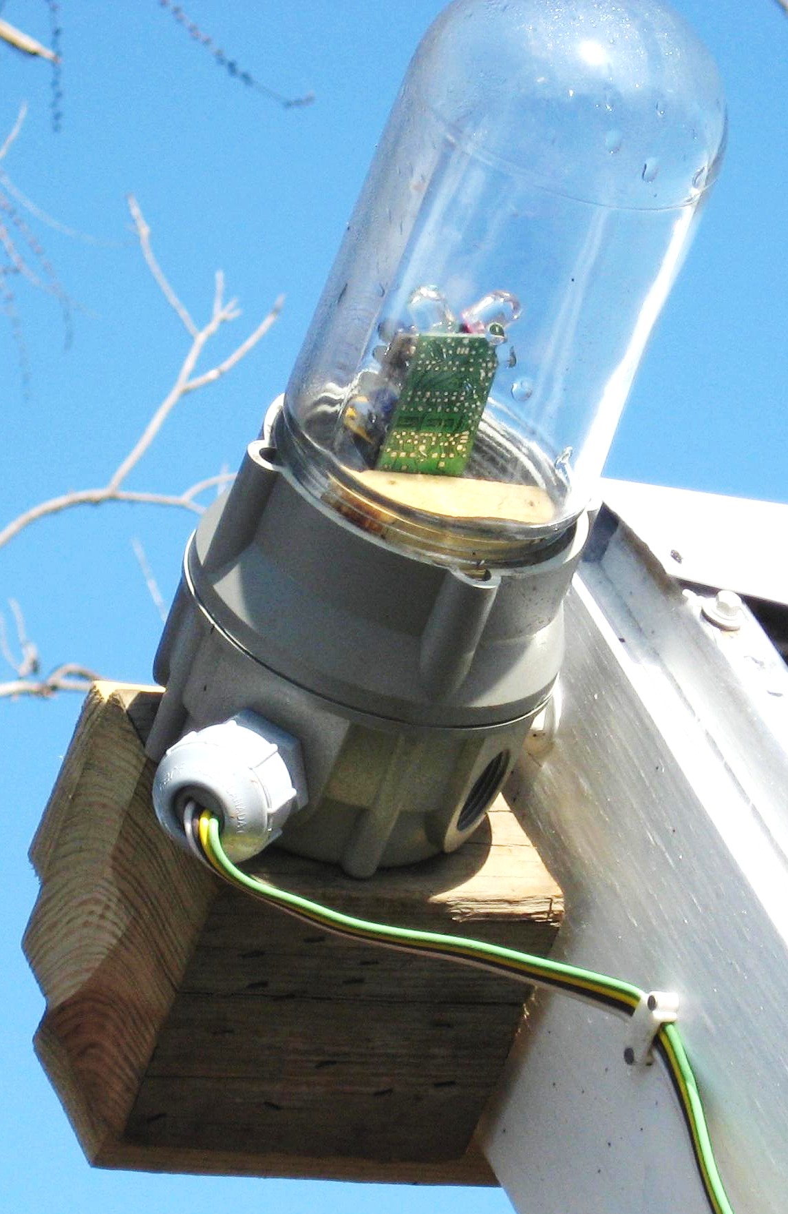
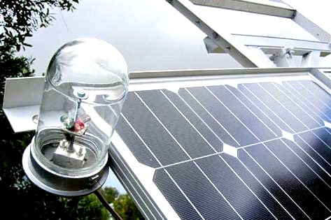
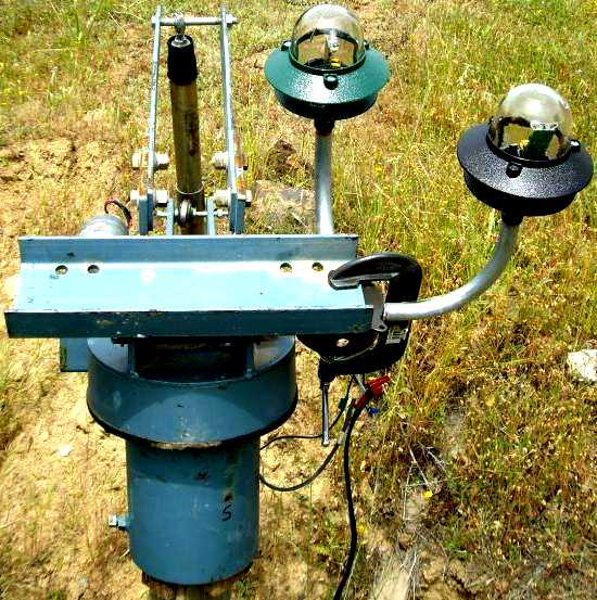
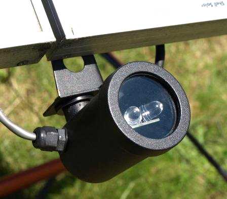
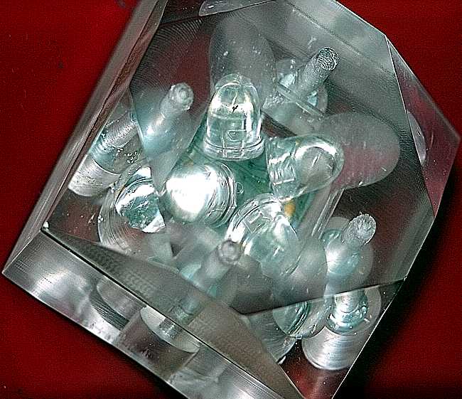
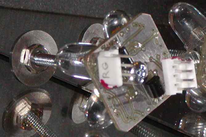 ReMote sensor. |
c1assm c1introduction The enhancements are: Other features:
c3assm
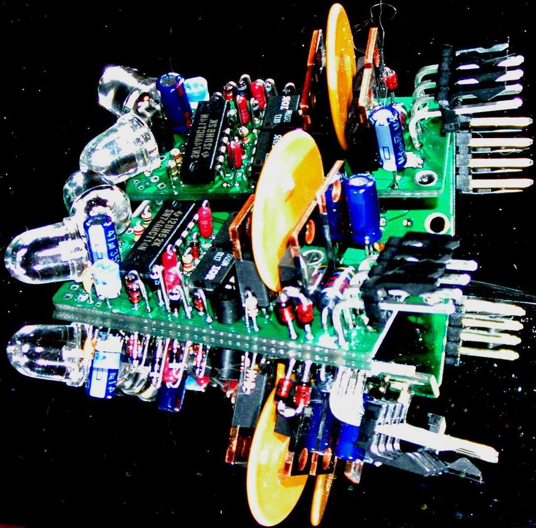
LED3Xc3 & LED3Xc1 Solar Tracker Assembly
c3introduction
Introduction:
The LED3X series of solar trackers are designed to drive satellite dish linear actuators. These actuators have built in limit switches.
Revision "c3" is nearly identical to "c1" but has some edited component footprints and some extra pads to allow the addition of a small daughter board for the reverse inhibit feature.
Revision "c1" was designed as an enhancement to "b2".
Other changes as noted below.
Revision "c3" are minor layout changes, I might as well do these when I order a new set of boards.
1. Adjustment for duty cycle from 0% to 100%. The cycle time is about "c3" = 60 seconds, "c1" = 18 seconds. ( This can be changed from a second or so to over 5 minutes if needed. )
2. Over current protection using a 3.75 amp Raychem PolyFuze resettable solid state fuse. This fuse limits the average current a bit over 3.75A. When tripped the PolyFuze goes into a high resistance state. To reset the PolyFuze one must remove power to the LED3X to let it cool down.
3. Over temperature protection for the MOSFETs by thermally coupling the PolyFuze to the transistors.
4. A higher current rating for the power connector of 7 amps. The pulse currents can be much higher. I have experimented with pulse currents of over 50 amps & 1/2 second, probably near the fusing limit of the traces on the board. Much higher average currents could be used if an external heat sink were used. (Ok, while the board was designed to be able to make use of an external heat sink, I have not found the need to try it yet.)
5. The board has mostly 15mil spacings to reduce the tendency for shorts.
6. The board has LPI solder mask to further reduce the tendency for shorts and reduces leakage currents.
7. 2 LED light sensor.
8. In addition to the standard sensor position that "looks" off the end of the board the LEDs can be positioned to "look" up from the board.
9. Wide operating voltage range of 10.5V to 44V for the standard unit to up to 91V for the high voltage version. While I haven't tried it, the voltage limit is 600V on the IR2184 power MOSFET drivers.( But who would want this anyway. )
10. Provision for external sensors, either close or very remote.
11. Under voltage protection of about 10.5V to both protect the MOSFETs and prevent damage to a lead acid battery that may be the power source.
12. The LED3X can be used as a general power H-bridge motor driver.
13. The normal board doesn't use a heat sink. Provision is made to use an external heat sink so the operating currents are limited only by the MOSFETs one chooses.
| Electrical specifications for LED3X24Vc3, LED3X24Vc1 | ||
| Parameter | Operating | Absolute Maximum |
| Input Voltage (12 / 24 volt nominal) | 10.5 to 44 Volts | -0.7 to 45 volts |
| Load Current with PSMN017-80PS (Standard 12 / 24V MOSFET) | 7.1 Amps 50 Amps with heat sink |
15.8 Amps for 1 seconds 150 Amps for 20mS |
| Load Current with IRFZ44N | 7.8 Amps 55 Amps with heat sink |
17.4 Amps for 1 seconds 220 Amps for 20mS |
| Load Current with IRFZ48V | 9.1 Amps 72 Amps with heat sink |
20.4 Amps for 1 seconds 290 Amps for 20mS |
| Load Current with IRF1405 | 13.7 Amps 169 Amps with heat sink |
30.7 Amps for 1 seconds 680 Amps for 20mS |
| Electrical specifications for LED3X48Vc3, LED3X48Vc1 | ||
| Parameter | Operating | Absolute Maximum |
| Input Voltage (48 volt nominal) | 10.5 to 91 Volts | -0.7 to 93 volts |
| Load Current with IRF520N | 2.2 Amps 5 Amps with heat sink |
9.7 Amps for 1 seconds 38 Amps for 20mS |
| Load Current with FQP46N15 (Standard 48V MOSFET) | 5 Amps 40 Amps with heat sink |
12 Amps for 1 seconds 180 Amps for 20mS |
| Load Current with IRFB59N10D | 6.3 Amps 59 Amps with heat sink |
14.1 Amps for 1 seconds 236 Amps for 20mS |
| Size specifications for LED3X series | |
| Parameter | Dimension |
| Length of the PC Board | 2.25" |
| Total Length Including the LED Sensors and Connector | 3.25" |
| Width of the PC Board | 1.00" |
| Total Width Including the LED Sensors | 1.25" |
| Total Height Including the PolyFuze | 1.25" |
Caution: An experiment I have done was to drive a 12V automotive door window motor. This motor draws about 4 amps at 13.8V. I raised the voltage to 44V with a pulse width of about 1 second out of a cycle time of 18 seconds. The peak current into the motor is 55 amps @ 1/2 second! Everything remained reasonably cool. Cool huh!
The LED3X series Tracker PC boards uses through hole parts. These components are easier to assemble than the surface mount parts on the previous LED3 tracker.
The assembly should be done in the specific order outlined to minimize the risk of damage to the circuits in case there are solder shorts or misplaced components.
Caution: Assembly Tools:
1. A low wattage temperature controlled soldering iron that can be set to 700°F.
2. Small diameter wire solder. I use Kester RMA, Rosen Mild Activation, based 37/63 solder in .014" wire size.
3. Metal tweezers for manipulating the tiny components.
4. Magnifiers or high magnification reading glasses. I use 3.5 or 4 diopter reading glasses.
5. Solvents to clean the solder flux. I use 91% Isopropyl Alcohol, available in the drug department. Cleaning should be done in a well ventilated area. Isopropyl is Flammable so be careful. You can also use "Heat" automotive gas line antifreeze. Don't use the newer isopropyl version of Heat, Red container, as there is some kind of residue left. Use the older methanol based "Heat" in the Yellow container.
6. A digital multi meter with sharp pointed probes for measuring resistance and voltage.
7. A current limited power supply that can be set to about .25 amps or lower. To further limit the current put a 500 ohm 1/2 watt resistor in series with the output. This power supply should be adjustable from at least 10 volts to about 18 volts to adequately perform the tests. It would be nice if the power supply can go as high as about 44 volts. However, make sure that you don't go any higher than 44 volts as this could damage the shunt protection zener diode D5. So be careful. 8. A bright light source for testing the tracker operation. I use a 150W halogen reading lamp.
c1schematic c1timing c3layout c3youtube c3assembly When I say to "Tack Solder" this means to solder one lead of a component on the top side of the board. I have arranged all the components so one easily accusable lead is always on the end closest to the mounting hole. The components are small and light and one can't turn the board over unless tack soldered because they will fall out.
Lay the board flat on a table and insert the components so the leads are flush with the table. This make for a clean flat back side. I assemble and tack solder all small components on the top side before turning over to complete the soldering.
Note! Some components may not be in the kit. These are for other options such as ReMote sensors, (CONN2, R11, R12) or direct drive control, (CONN3, R10).
Also! There have been some substitutions of parts throughout the circuit. These were done mainly due to parts availability. OK, to be honest, I got some good deals on parts at ebay. I will comment about substitutions throughout the assembly instructions. These substitutions generally improve the circuit reliability.
The most important test to perform is the Ohmmeter test. This board is laid out in such a way that almost all circuit traces can't short out to each other, rather, these shorts will be to ground. Shorts can be caused by a variety of things. The most common is a solder bridge but shorts could come from the PC board manufacturer also. The Ohmmeter test is easy to do. Just set the Ohmmeter to something like 20K Ohms with the - terminal connected to the ground plane. The + lead then tests all the circuit pins looking for zero ohms or shorts.
Don't worry if a higher value is read as this is most likely just the forward drop of the circuit junctions. You can prove this by changing the Ohmmeter scale. If it is a junction the resistance value read will change. If it is a true resistance the value will be the same.
Step 1. Mount all horizontal components.
Step 2. Tack solder the top side.
Step 3. Mount all the vertical small components.
Step 4. Tack solder the top side.
Step 5. Q5 MPSA18 NPN Transistor. This can also be a BC337 or 2N3904. Note! the different orientation if a BC337 from the diagram. When mounting Q5 keep the body above the PC Board a bit so it can be effectivly cleaned of flux later. Step 6. LED1, LED2 Large 10mm Lumex Green clear cased LED. (Not used if this is a remote sensor version.)
Step 7. CONN1
Step 8. Turn over and solder all installed components.
Step 9. Install the PolyFuze and solder.
Step 10. Do an Ohmmeter check to see if there are any shorts to ground and fix any.
Step 11. Turn the potentiometer clockwise to 50 Seconds, Step 12. Install Q6 KSC2330YBU or 2SD667-D NPN Transistor and solder. A BC337 or 2N3904 can be used for 24V operation. Note!, the different package orientations. The BC337 or 2N3904 needs to be installed with the Collector and Base leads reversed. ("c3 revision" has the leads correct for the KSC2330YBU and 2SD667-D.) Step 13. Do an Ohmmeter check to see if there are any shorts to ground and fix any.
Step 14. Turn the potentiometer clockwise to 50 Seconds, Step 15. U3 74AHCT14 hex Schmidt Trigger logic gate and solder.
Step 16. Do an Ohmmeter check to see if there are any shorts to ground and fix any.
Step 17. Turn the potentiometer clockwise to 50 Seconds, Note! U1 pin 2 is actually a pulsed signal that's about 20% 0 volts and 80% 5 volts at 1.7Hz for the "c3 revision", (was 250Hz in the "c1 revision").
Note! This assumes low light on the sensors to simulate Parking.
Shine light onto LED1
Step 18. U1 and U2 IR2184, Q1, Q2, Q3, Q4 and solder. Step 19. Do an Ohmmeter check to see if there are any shorts to ground and fix any.
Step 20. Add C7 47uF 100V Capacitor. Observe the polarity. The stripe is ground. And solder.
Step 21. Turn the potentiometer clockwise to 50 Seconds, Step 22. Apply full unlimited power to CONN1, +11 volts between pin 1 + and pin 4 -.
Be very careful and make sure the current isn't more than a few 10s of mille Amps. The drivers can be damaged if the current is excessive due to a circuit short. Remove power immediately if a fault is detected, especially if the drivers get warm. And test for:
Observe the operation of the indicator LED.
Drop the power supply voltage to less than about 10 volts. Adjust the power supply to find the point where the indicator LED operates. This should be around 10.5 volts with a hysteresis of about .5 volts or so. This parameter is fairly loose in the IR2184 specification. Step 23. Connect a reversible permanent magnet DC motor with limit switches between CONN1 pins 2 and 3.
Observe the operation of the motor to see it go reverse, stop, and forward by moving a bright light in front of the sensors.
Observe the operation of the limit switches. c3pot pete Step 25. Good luck.
Step 26. If you are building an RI, Reverse Inhibit, or RI, Limit Switch, version continue onto: How I do it? I use an assembly board that holds 11 units. I first hand solder the two SMT parts, then place the LED sensors and connectors. I then place all the other parts. I use a small solder pot to dip solder the whole board. I use a very nice high activation solder flux that must be removed shortly after soldering. This stuff is like magic.
I clean up the possible solder bridges and failed connections.
I then test the board using a VERY GOOD current limited power supply, a Kikusui PAL 35-10. This power supply prevents damage to any parts if there is a solder short anywhere on the board. c3c1operations LED3X Solar Tracker Operating Instructions
c3c1installation Installation: jiff It can be mounted almost anywhere on the movable portion of the mount. Generally the best location is on the north eastern quadrant. (South eastern in the southern hemisphere.)
Be careful to avoid reflected light. One of my customers had quite a bit of a problem with reflection from the panel frame. The solution was a small light blocking between the reflection and the sensor.
In general, mount the tracker so the sensors are "even with" or "slightly behind" the plane of the PV Panels. These trackers are designed to drive "Permanent Magnet DC Motors".
Most of my customers use satellite dish actuators to move their mounts. The nice thing about satellite dish actuators is their relatively slow speed of motion, low operating current, and the integral limit switches and they are usually quite well built. However, I don't put them in the "Good" category as they ARE linear actuators operating lever arms. This causes the speed to vary throughout the day and have poor mechanical advantage at the extremes so, generally, are limited to about 150 degrees of rotation.
I like running 24V or 36V satellite dish actuators on 12V so they move at 1/2 or 1/3 speed. Permanent magnet DC motors generally don't have a problem running at the lower speed and the developed torque is only marginally lower than at rated voltage.
Many of my customers build their own drives. The most successful have very high gear ratios and use "Rotary Motion". I recommend the total gear ratio be something like 100,000 to 1. 300,000 / 1 is even better. I like to see the system take at least 10 minutes to go from limit switche to limit switche. 1/2 hour is even better. 1/2 hour is still 24 times faster than the sun moves.
It's a REQUIREMENT to have limit switches in the motor circuit. When the tracker goes to park it drives the motor to the east and doesn't stop. The limit switch stops the movement. So you just have to have limit switches!!! parking Normal tracking motion will resume immediately when the sensors see bright light again. dualsetup The standard way I like to setup dual axis tracking systems is to make the PV panel or other concentrators orientation to Park overnight in a position, generally, vertical so snow, water, or leaves can be shed. Usually this means moving to the East and South in the Northern hemisphere. Or to the East and North in the Southern hemisphere. The notation on the remote sensor is for the Northern hemisphere.
There are 4 basic orientation combinations for the standard remote sensor because both halves are normally built for Parking.
These sensors can be made as No-Park types also. Or one side Parking and the other No-Park as required. That makes for 16 different orientations and types.
The first thing to do is remove the remote sensors to initially setup the motors for parking the way you want.
Each power unit has a small white square surface mount indicator LED next to pin 4 on the main connector. It flashes Green for forward and Red for reverse or the Park position. With the remote sensor removed it always heads to the Red or Park position. Make sure the motors are moving in the desired Parking position. If they are going in the wrong direction reverse the wire connections to the motors going wrongly. The motors are now moving correctly.
You may want to set the motor timing to 100% ON by turning the small 1/8" (3mm) square surface mount control clockwise to 50 seconds Make sure the limit switches are correctly set otherwise mechanical damage to the motors, mount, or the PV panels could be damaged, an expensive lesson.
The LED sensors on the Remote sensor have been painted with Red and GREEN paint to help understand which way the motors will be moving. Again Green is forward and Red is reverse or Parking direction.
Rotate the sensor in such a way that the RED sensors are orientated in the desired Parking directions. Now connect the power units to the appropriate connectors. The notation on the connectors have an arrow sort of pointing to the sensor pairs with which they are associated.
Hope that helps.
polaraxis The best solar tracking mounts have the main axis aligned with the polar axis and rotates in Right Ascension, sort of East and West.
If dual axis, the secondary axis is oriented 90° to the polar axis and rotates in DEClination, sort of North and South.
To set the Polar Axis, angle the North end up from the North horizon by your local LATitude.
pseudo There is quite a bit of confusion about "True" vs "Pseudo" polar axis mounts and how they operate. Polar Mounts on Wikipedia The difference between solar and satellite use is the solar application will have no offset angle. The sun is a long distance away and the satellites are much closer. Offset angle is caused by ones location on the earth. At locations other than on the equator the one needs to look down a bit to see the satellite at an orbit of 23,000 miles. This effect is essentially nil for the sun at 93,000,000 miles.
True DEClination is the seasonal adjustment, a tilt "ON" the main or polar axis. Not the polar axis itself. The example shown is for a satellite dish but is equally applicable to anything needing to be tracked. Once the true polar axis is set it is permanently fixed never to be changed. Seasonal adjustment is done only with the DEClination angle.
Lots of people have what I call "Pseudo Polar Axis" mounts. They adjust the main axis up and down to simulate true DEClination. Moving the main axis up and down is what I call "Pseudo Declination". This works OK for flat panel or low concentration use, 10X or so. However, there is considerable tracking error compared to the true mounts. Error is greater near the solstices and zero at the equinoxes. I would not use a pseudo polar axis mount on any concentrator of more than 10X or so.
Of course the daily motion, or Right Ascension, works in the normal way.
Just to be complete: Great page on dish specs. High winds are unpredictable. Especially a type of wind called a "Downburst" or "Microburst".
This is usually the highest survivable wind. OK, tornados have much higher wind speeds but are not survivable nor predictable. Hurricanes have very high winds and quite predictable so the panels can be removed and stored.
When I design tracking mounts I use the local building code horizontal wind loading specification. In my locality this is 10 lbs/ft² at 90mph. In Florida this is 15 lbs/ft² at 105mph. I assume the tracking mount must withstand these winds in any orientation at any time.
Normal "weather" based wind is generally limited to a peak of about 70mph or about 5 lbs/ft².
Wind pressure can be calculated with this general equation. BTW, some localities such as mountain tops and deep in valleys can have peak wind speeds far in excess of the above recommendations.
I never use wind sensors for shutdown because this would only give false security. Just make the mount strong enough in the first place and you shouldn't have any problems.
Some ask why not "Table" or park with the face in a horizontal position looking strait up at the zenith. Several reasons.
1. Hail damage is more likely in this position.
2. Some want to move into the table position when a wind sensor detects high winds. They mistakenly think they can save cost by using a lighter weight mount. However, in the case of a downburst, which can happen in seconds, there wouldn't be enough time to go to the table position. The wind sensor is just "False Security". Make the mount strong enough to take any reasonable wind at any time in any orientation.
3. When parked overnight with the face oriented, generally looking at the horizon, snow and ice sliding off in the morning partially cleans the surface. (Of course, periodic maintenance cleaning must still be done, but the snow really does a good job until springtime.)
4. And of course, with a dish it would just fill with water. Nice for the birds but bad for the reflector.
windsensor I have the standard LED3XS24Vc3P solar tracker available for sale for $35.00us fully assembled. This includes the power connector and 5 pins (an extra pin, just in case).
I have a number of variations for special applications. Please email me for particulars on special application trackers including versions with: sh wu Please don't forget to include:
Your shipping address. Places I can't ship to: Problematic shipping to: I don't accept credit cards.
whatubuilding address Email address: Phone number: Note! All the standard trackers have the "Parking" feature unless otherwise noted.
Top. Normal operation between limit switches. Select a diode or rectifier rated at the maximum motor current plus some margin. Also the voltage should be at least 100V and preferably 200V.
Needles to say, the limit switch must operate before the mechanical limits are reached. If the mechanical stop is reached before the switch the motor can draw quite high currents and can destroy the solar tracker, motors or even the thing being tracked.
limitthermostat Of course, parking and limit switch operation is unaffected.
power Ok, lets get serious here, there is no earthly reason to require high powered motors. The Sun moves very slowly so low power motors with high gear ratios work best.
relaydc1 I basically don't recommend using relays or contactors in DC current solar tracker applications. The tracker will be energizing them thousands of times each day. This tends to wear out the contacts, especially in DC circuits. In 10 years that would be about 7 million operations. Not all relays can handle that. If you have to use relays make sure they are SPECIFICALLY rated for use in low voltage high current DC applications. Mercury Plunger relays are the best as they also don't have a wear out problem.
relayac1 relayac2 manualops Some of my commercial customers like the 2nd circuit. Essentially, forward and reverse manual motion is done with 2 pre wired plugs. Just unplug from the tracker and insert the pre wired plug. This guarantees that no damage can be done to the tracker because it is entirely out of the picture.
The power contacts are sized to accept a wire size up to 18 gauge. I usually use 24 gauge. High current motors may need a bit larger wire. However, even for high current motors large wire size is not required as the average current is less than an average of 3.75A.
The tracker was designed to be used in the northern hemisphere and park in the east. The components will then be up on the board. To use in the southern hemisphere flip it over with the components down. If the motor tracks in the wrong direction just flip the motor leads around.
If you want to park in the west, (not recommended), flip the circuit opposite from above.
trough This turns a bit fast without speed reduction but this was only a test besides it can be slowed down considerably with the duty cycle control. The diode that shows on the side of the motor is one of two across the limit switches on this gear motor. The motor was originally used on vending machines, and paper shredders, however it is no longer in their catalog.
Thanks for the pictures Patrick!
Note!, the current revision LED3XS24Vc3RM variant with external sensor, and connectors costs $45us + $4us s/h. The new one includes a single axis ReMote sensor PC board called the LEDSRMP with parking. A pack of all parts is the LEDSRM24Vc3PPack.
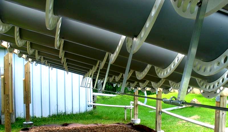
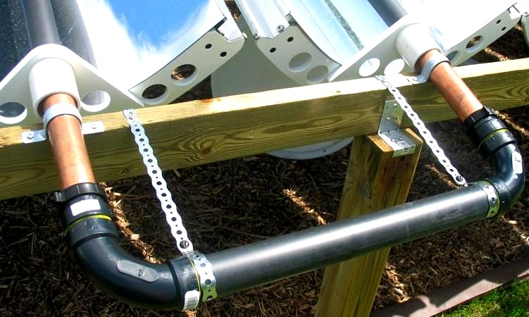
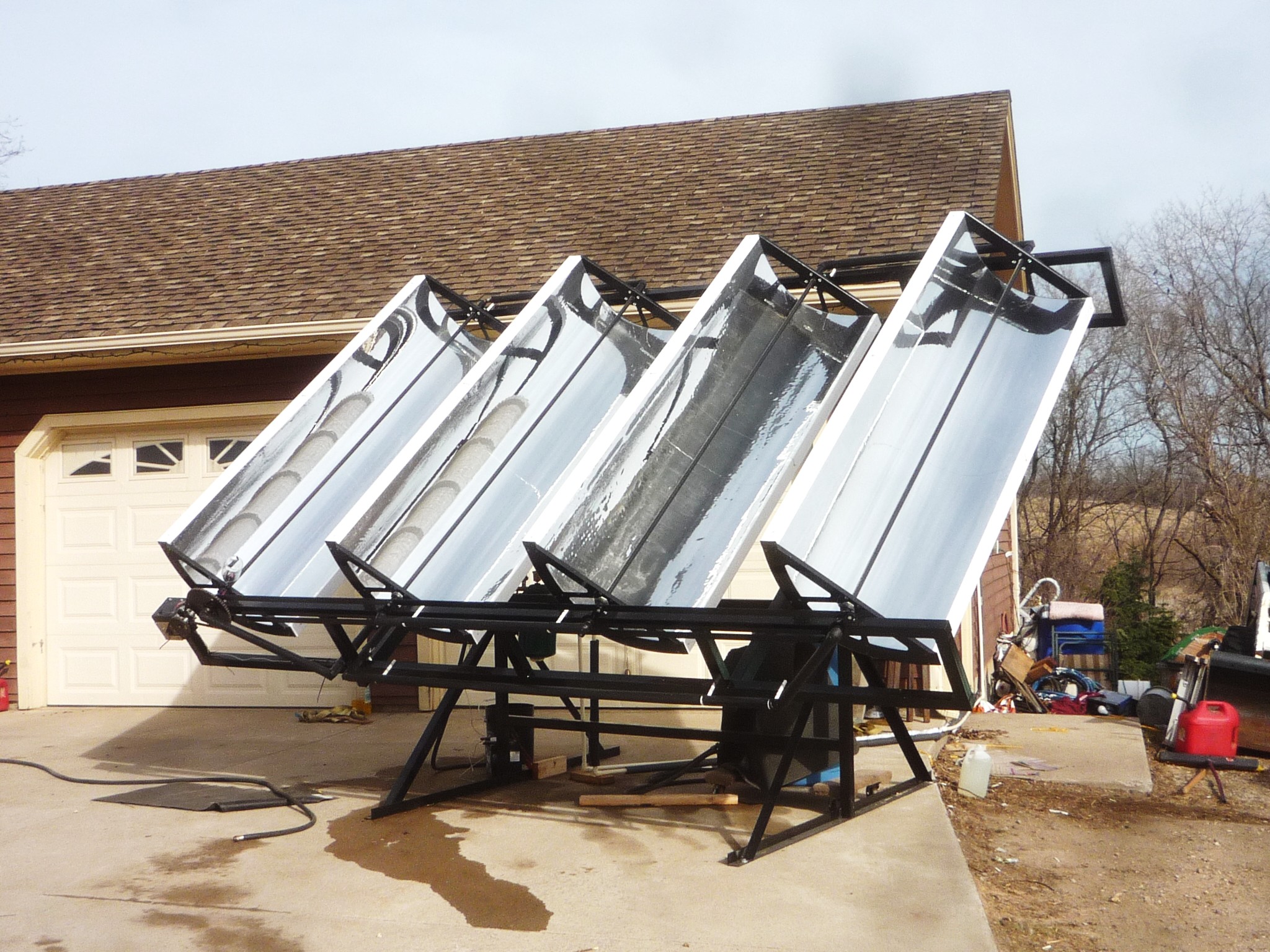
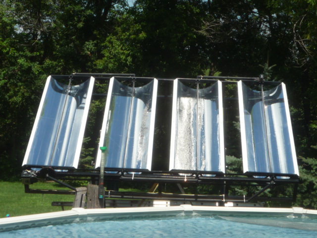
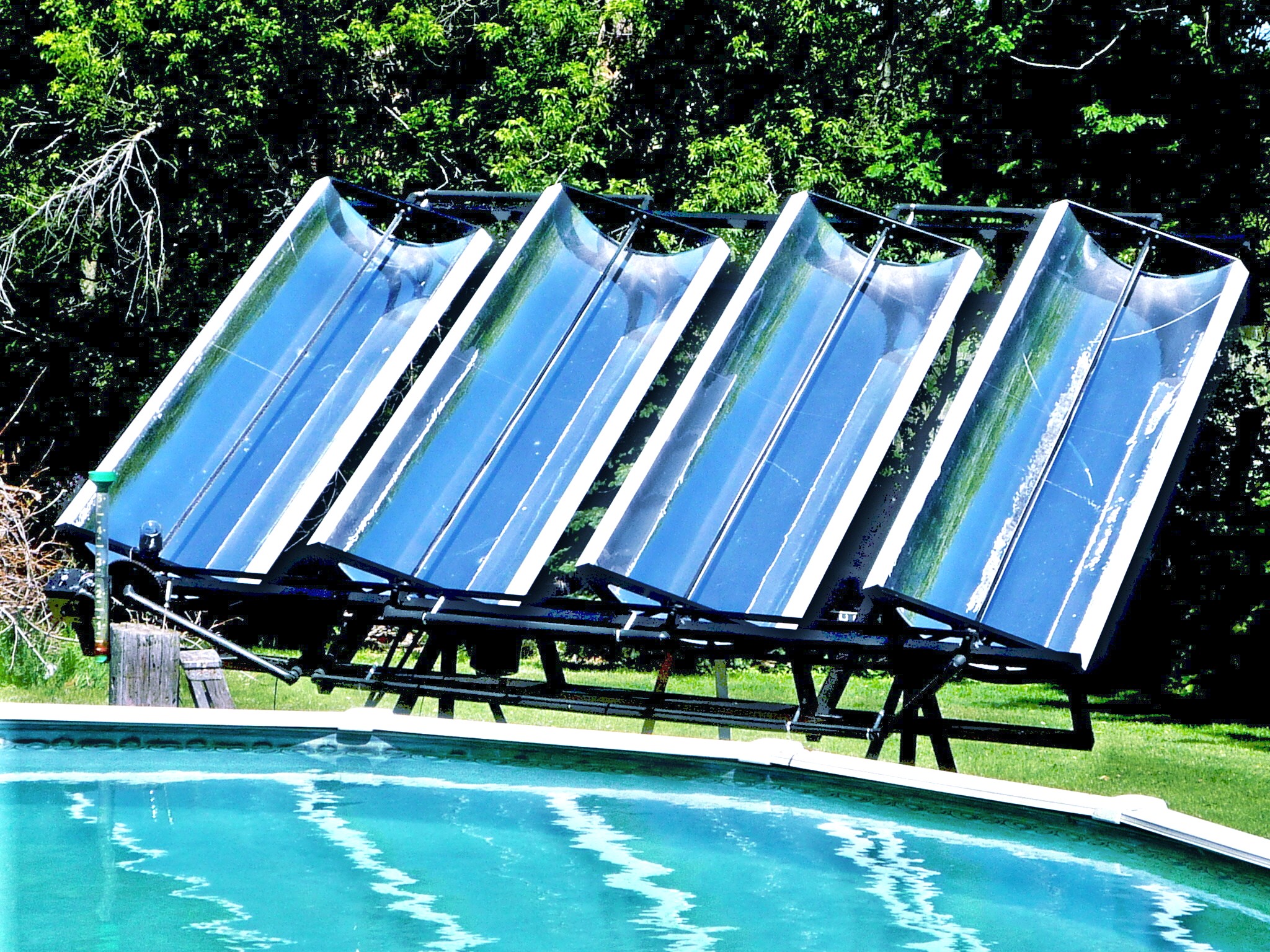
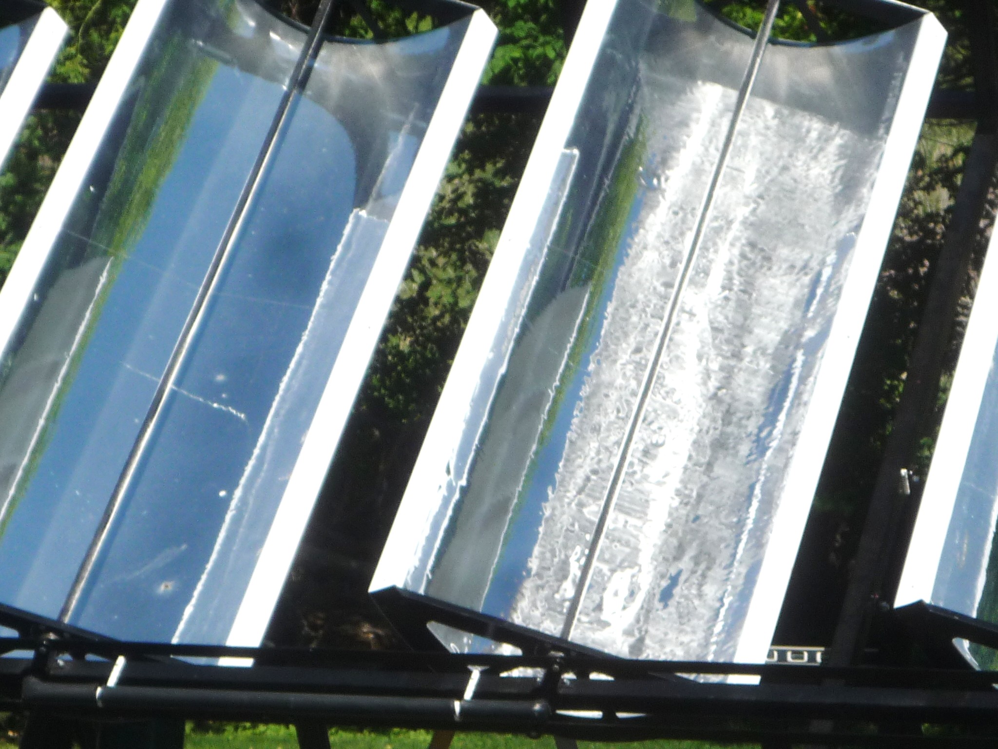
george George has a beutiful looking activly tracked trough array. The parabolic troughs are arranged so the main axis oriented in a North-South direction. The North end has been elevated a bit so the main axis is between horiziontal and polar.
The water piping doesn't move, similar to Rowe's example above. This method has a distinct advantage as there are no rotary joints that can cause leaks. Cool huh!
The LED3XS24Vc3P tracker is enclosed in a weatherproof enclosure from Leviton. George is selling plans and passibly some hardware parts for this project. smith Ron Smith has built this impressive polar axis parabolic trough water heater.
He says, "The unit runs well and produces the same water temp rise As a 7 KW mini boiler. That would be: britton envsolar grabon solarthermo Note!! A basic measurement needed for accurately determining performance is the "Stasis Temperature" of your particular collector. I describe how to do this in the documentation as well as in more detail here.
I wrote this using Excel 2007 but works with older versions too. If there are any errors please report them to me at <redrok@redrok.com>.
lee Gary Reysa of Build It Solar published Lee's system.
We don't see very many tracked flat panel water heaters. They are benefited by tracking by reducing cosine losses. However, they still have low collection efficiency compared to the concentrators.
He is using the LED3XS24Vc3RIP Single Axis Solar Tracker with Reverse Inhibit.
shadowing set Worse yet, as in the picture above you can clearly see that shadowing is already occurring. Of course, if the panels were spaced further apart they could rotate more without shadowing. but that would mean length at greater expense.
As of 2017 or even a couple of years ago, PV panels are getting so cheap the East/West motion in this design is not needed at all. Just pack more panels in the same space. Remember, all East/West Horizontal Axis tracking mounts suffer severe "Cosine Losses" in the East/West direction. If you consider the total area of the mount, not just the area of the panels, there is no increase in the energy production of the SET design over the same mount area covered by panels. (Ok, the SET design may do a bit better because they have less "Snell Reflection Losses", although modern panels tend to limit this.)
Anyway, if you require an East/West Horizontal Axis tracking mount just fill the mount with panels and use a single axis North/South axis tracker.
More Importantly!!!! How I would do it.
I believe this tracking mount should be orientated North/South. And possibly the North end raised to reduce the shadowing effects to greatly increase the captured energy per day. See the Excel "Shadowing Spreadsheet".
This design is well built and should be a good example of a dual axis system, if properly orientated North/South.
They are using the Yokogawa HXS10 microprocessor solar tracking controller. This is a very nice unit, albeit fairly expensive. The HXS10 can also drive heliostats. The SET East/West mount would work nicely with mirrors for lighting heliostat applications. The Yokogawa HXS10 knows how to do this. scorpius I'm not going to second guess the reason they are not spacing them a bit further apart to lessen shadowing effects. I suspect they are maximizing power output near noon vs more even power output for more of the day with more spacing.
You can see the "BackTracking" motion to prevent any shadowing, similar to the motion in the SET design.
Scorpius does have a unique flexible, kind of a leaf spring, mechanism which eliminates any bearings. Their design used springs. However, a similar thing can be done with tension bands or cables wrapped around a pair of circular cylinders.
loonstra epicycloid While there is metal to metal contact I'm not sure it can be called a "bearing" as the metal surfaces don't slide over each other. Just as in the Scorpius spring design no lubricants would be needed.
Technically, the Epicycloid Bearing can be superior to the Scorpius design as it can rotate at least 180° and probably to 360°.
See some info on the Epicycloid Curve. This example would be of the "k = 1" form.
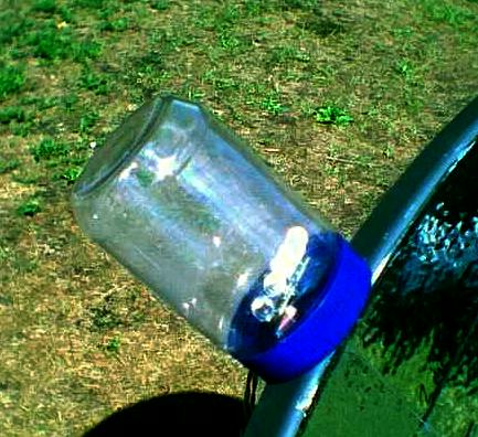
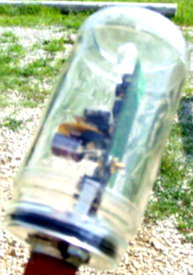
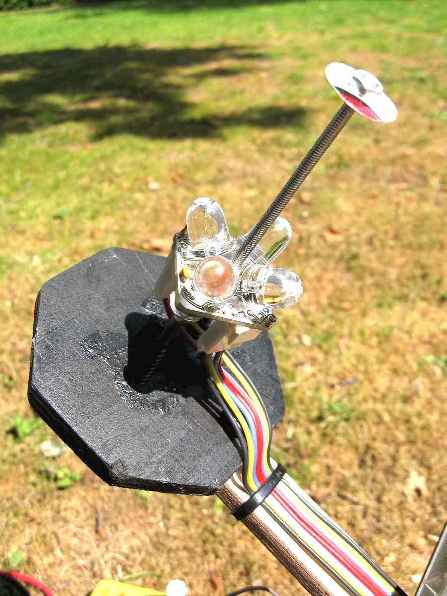
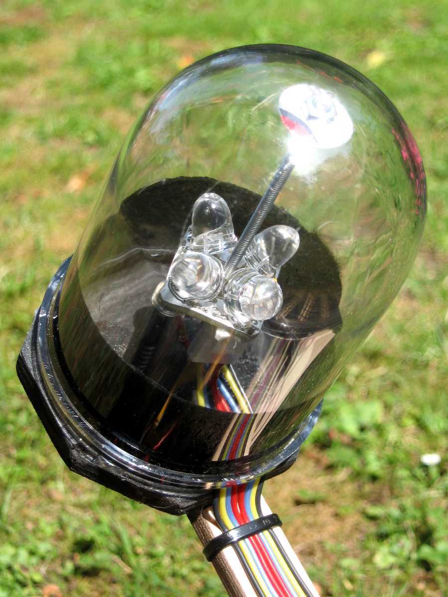
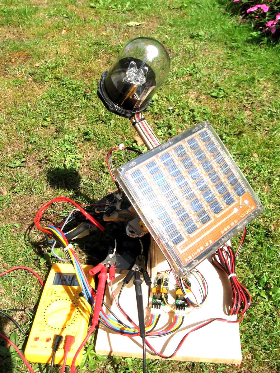
youtube paulpakelson lancette This design uses a "Sanka" coffee glass jar mounted on an aluminum plug he machined. It includes an O ring for a seal and friction lock. This plug is threaded onto a conduit which acts as a mast, a wire way, and a vent.
The motor is a Grainger 2l008. 8 rpm with a gear ratio of 603/1. This makes for a total gear ratio of about 1,200,000/1.
instructable1 Note! There is a serious flaw in this Instructable. A bicycle wheel rim is perfect for a "Rotary Motion" drive.
Small high gear ratio DC motors are a much better choice for the drive motor, and a lot cheaper too! LED3XS24Vc3P $35us plus shipping tracker can be used with high gear ratio motor drives. Cut a large rubber band out of a bicycle inner tube and use the motor shaft itself as the drive pulley. I recommend adding a counter weight to the wheel that is opposite the panel to balance the weight.
Shipping is $4us inside the us or $10us outside the us for any quantities.
Limit switches are required.
wolfgang
This project has been a bit of a struggle. We first tried to to use the LED5 low power solar tracker as Wolfgang was using high gear ratio motors rated at 100mA. However, during storms the high winds caused overloading and burned them out. Unfortunately the standard LED3X high power solar tracker would try to park at night, but there are no limit switches in the system which would cause the panels to turn all night, not good. The solution was to add the "no park" feature which worked perfectly for him.
See how the constant tilt PV panels can rotate under the boat railings.
teton martinez solartony theismann moore He choose to use a pair of single axis LED3XS24Vc3P trackers. The mount is a rebuilt Wattsun unit.
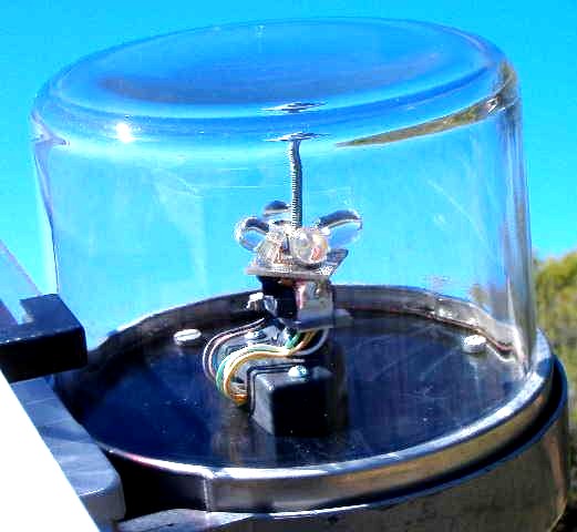
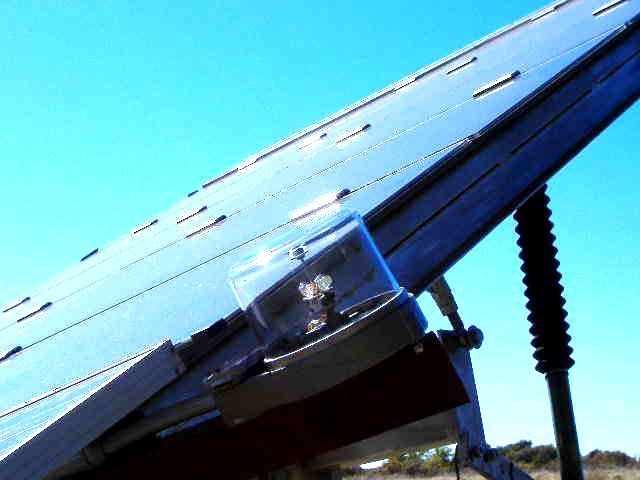
hoskin " Thanks, the LED3X is an elegant design, and I speak as an engineer. I stuck it in an outdoor lighting can I got from the local hardware store.
I've included a couple of pictures, including one that shows the original Wattsun controller (now defunct, but still useful as a shadow post). I originally built up this system to see if it was possible to charge my electric bikes solely from a small PV setup. This answer seems to be: yes, for about 5 months of the year in Seattle.
I got the can at Lowes hardware here in Seattle. It's a Luxar #144175 black 10W halogen light made by Manor House. I stole the weatherproof cable entries from the original Wattsun tracker, and bent up the internal bracket that held the light to mount the board (how about another mounting hole on the board, btw). The best thing about the can is the front glass screws off to make adjustments, but still has a nice rubber gasket to seal against weather when on."
lexan Note, I do not recommend casting the circuitry in the resin as, long term, there can be damage to solder joints due to differential thermal expansion.
scratchbuilt lenox witherspoon pezant carmen juiceguy Henry modified a fixed PV panel mounts by Power-Fab. The weather dome is the glass Model: 62480 replacement globe from an outdoor light sold at Menards. The tracker is an LED3XS24Vc3P mounted in the North/South orientation.
bernd meunier plunk kozlowski mcintyre bray rhodes tripod javier See:Tripod Mounts
There is a problem. The tracker is not oriented correctly. It should be tilted up 90° from what you see in the picture. Sure, it still operates in a normal manor but the directional sensitivity is reduced.
That weather dome is an outdoor light fixture. Yes, its thick glass which I don't generally like but this one is working fine.
hill energyoptions gordon brown The panel drive is a linear actuator from Firgelli Automations. Part #
FA-05-12-24. Rob says they seem of good quality and the price was right. However, the limit switches are not adjustable on this design and it's a bit fast at 3/4"/s.
Easterly extent is limited by one of the actuator's limit switches. The geometry extents do not permit the use of the other one for Westerly extent, which does not signify at this time of year, but I am going to fit a separate switch for that, one of the coil-spring sensor ones, like a pinball machine switch, before the days get longer. The output goes to a junction box in the greenhouse with an armored cable, of handsome cross-section, running to the basement of the house.
Robert's glass weather dome was a bit cramped to be able to use the connector which extends out the back end. So he soldered his wires directly to the board pins.
Note! I can supply the unit with the connector mounted in other orientations: Robert glued the board to the top of a plastic post using epoxy. While this can be done successfully gluing is generally not a good idea. Especially don't use the RTV silicone with acetic acid retarder. The acid can damage the board or prevent proper operation of the circuit. And don't do anything to the front end of the board forward of the IR2184 MOSFET drivers.
I just don't recommend gluing at all. There is a hole in the corner of the board that accepts a 4-40 machine screw.
simmons Walter Simmons built this very nice pseudo polar axis mount. satellite
roberts taylor wylan parish flores volvo djpitr scrapit85 He is using an LED3XS24Vc3P single axis solar tracker. moleiro The LED3XS24Vc3P is in the glass jar.
It has six 75W panels with space for two more. He also has a wind turbine. They power his ham-radio station and the lighting for his house in Portugal.
wheelrim The vertical axis can rotate as many degrees as required. The drum, actually a small tire rim, is fixed to the main pole. The cable is moved with the linear actuator. When moving the actuator assembly and dish rotate about the fixed drum in AZimuth. The dish moves in ALTitude with the secondary tilt actuator.
He is using an LEDDRMPP24Vc3Pack Standard Dual Axis Solar Tracker with ReMote sensor and parking on both axes.
In general the mechanics works well but the speed of rotation is to fast. Linear actuators already move fairly fast, this makes things move even faster.
vertical
thompson The basic array motion is done with cables wrapped around wheel rims and driven by a single centrally located solar tracker, (in this case an LED3XS24Vc3RIP). The tracker is mounted on a large diameter chain driven pulley or "Not A Sprocket". The plane of this pulley is parallel to the plane of the main axes of the multiple tracking mounts. Note, the chain is bolted to the "Not A Sprocket" just as the cable is bolted to the wheel rims so there can be no slippage.
The gear motor's, in this case a small Suzuki windshield wiper motor, relatively fast rotation speed of 50 rpm is converted to a low speed high force drive through a string of bicycle derailleurs and a final plywood "Not A Sprocket". This is mounted on top of a wheel rim of the same size and orientation, vertical axis, as those on the multiple tracking mounts.
A single cable is wrapped around the multiple wheel rims. Since all the the wheel rims are the same diameter they all rotate synchronously at the same rate and controlled by the tracker.
In this case the tracking mounts are arranged vertically or aimed 90° above the horizon to the zenith and rotates about the horizon in AZimuth. He has a secondary horizontal axis manually adjustable in ALTitude. This is not ideal as good AZimuth/ALTitude tracking mounts should have dual axis trackers to gain maximum energy per day, about 20% or so over a fixed ALTitude. With the cable arrangement it would be difficult to do this so the energy per day will be a bit less than ideal. Even so, there will be significant energy per day gains over fixed mounts.
Andrew had been having tracking problems that I think was caused by reflections from the back sides of the front row of PV Panels. The back side is white and diffusely reflects a lot of light which was confusing the tracker in the morning. By moving the tracker to the top of a PV Panel in the south, or front, row these problems have been eliminated.
Gear ratio calculations: This arrangement is superior to Garrison's "linear to rotary" mechanism for rotary motion.
See a YouTube of the operation of his system. My comments: west cnewton Note! His electric output is about 100W. The turbine output was about 500W. There was a major mismatch between the turbine and the generator. (He said he ran out of money.)
geotrack cross jory He needed a low cost light weight system to power the camera with a PV panel. We decided that a tracking mount was the best solution. There is a lead acid battery to run the camera when the sun is not out.
The Steca Solsum 6.6c LVD charge controller has a low voltage disconnect feature to protect the camera and not allow the battery to be discharged excessively. This charge controller was taken out of its case and installed inside the Lexan weather dome.
I made 2 versions. The big mount was for a 30 watt panel and cost about $275us total. The small one was for a 10W panel and cost about $235us total. Ok, this does not include the $1600us Panasonic camera.
LED3XS24Vc3P solar trackers were used in both units. sg2100 This tracking mount is based on the $70us Sadoun PowerTech DG240 H-H, horizon to horizon, small dish mover and LED3XS24Vc3RIP solar tracker with Reverse Inhibit. The DG240 is designed to support a 1.2 meter aluminum dish. This is equivalent to about 13 square foot of area. A crystalline PV panel has an efficiency of about 16% or about 15W/ft2. This implies that this mount can support about 180 watts of crystalline PV panels. The panel in my example is rated at 30W and is 13"x23". Note! This class of satellite dish movers have been designed to be operated with DiSEqC control signals. My solar trackers don't use the DiSEqC controls. They only operate the motors and possibly the limit switches.
Or the larger 1.4 meter aluminium dish unit capable of supporting about 23 square foot. Or this is available with a smaller diameter mounting shaft for 1.0 meter aluminium dish unit capable of supporting about 9 square foot. The main bearing is what appears to be a sealed ball bearing type. The secondary bearing is an Oilite type. The main worm gear is capable of rotating 360°s.
Cool thing, the DG240, and DG280, have what I call "conventional" internal limit switches.
(I have another H-H mount, SG2100, that has "unconventional" limit switches which are not as easy to use. I have a possible method to use the internal switches, but this is untested. The simplest method is to use external limit switches. There is another model available, the DM-2100, but I have never seen this one.) If the limit switches are removed the unit can be rotated 360°s and be used with a "no park" tracker. Of course "slip rings" would be needed. In this case the shaft would be stationary and the body would turn.
I have a customer that used a DG240, with limit switches removed, as just a motor. He attached a chain sprocket, the smallest he could find, to the DG240 and a large flat belt sheave with the chain bolted to it. The final drive was about 20/1.
I gutted the unit by removing the main board and motor drive board. I also removed the center positioning switch. The Yellow limit switch wire is soldered to the marked motor terminal, (Red dot). The Red limit switch wire and the second motor terminal go to the LED3X tracker motor terminals.
Note! This drive is a bit fast so the RI, Reverse Inhibit, feature daughter board must be installed!
I have tested this motor on 36V with no trouble. However, 12V is a better choice. Even at 12V I would put the speed in the "Fast" category. This definitely requires the "RI" or Reverse Inhibit feature installed. This tracker is the LED3XS24Vc3RIP.
Note! The mounting pipe, in this example, is mounted upside down from the normal "Dish" position. The little metal arrow must be filed off so it will not interfere with a metal tab on the case.
windvane This should work well because, generally, the wind direction doesn't change direction as fast as the boat does.
This idea can also be mounted on a deck.
pardell poulo parrot water hawk led3xc1mods np rs Another method is to use a thermostat in conjunction with the limit switch circuits. ri If you are an "experimenter" I don't recommend the "Reverse Inhibit" feature as the operation is very slow to react to abrupt condition changes such as putting your hand in front of the sensor to effect a quick change in direction. I like the RI for my commercial customers who don't mind this. It's kind of like "watching paint dry". I can't have this when I do a demonstration.
There are some restrictions in the use of the RI mod. Yes, the RI was designed to prevent "Hunting" with fast motors. However, if the motors move to fast they can overshoot the capabilities of the RI. The RI is expecting the Sun to catch up during the timeout period. 3 minutes is equivalent to about 0.75° of Sun movement. So if the motor overshoots by greater than 0.75° the next cycle will move in the opposite direction. And then repeats again the other way. I have seen this happen in a few systems.
Some of the problem can be alleviated by reducing the motor movement time. I set the trackers or a movement time of about 2 seconds when I ship them. The control can be set from 0% to almost 100%. I don't recommend setting this control to less than 1/2 second as most motors loose torque. This control is a small black square surface mount part. Although it looks like it's a Phillips driver, it's not, you should use a small flat bladed screw driver.
Another problem can be caused by a weak, loose, or flexible mounts. This is usually evident by a mount that is not stiff enough and can be moved by hand by more than the 0.75°. These mounts are technically not strong enough and probably wouldn't survive in a 10#/ft2 wind load anyway.
motors rivid ( Note! This mount is very light weight and is using a fairly fast "industrial" type of linear actuator. Generally one should use C-band satellite dish linear actuators or, better yet, use high gear ratio rotary motion drives.)
lsmod Note! I don't recommend this type of limit switch because they are not inherently fail safe. If the switch becomes corroded or the wires to it break NO limit switches will not function properly and severe damage to the mount, stuff on the mount, or the motor drives can occur.
rilsmod riinstallation led3xremotesensor
The ReMote sensors can be configured in several flavors. The PC board is configured in 2 halves. Each half is an individual single axis sensor. For single axis use the board is cut in half or dual axis if left whole. Depending on which components, positions, and jumpers installed all the configurations can be obtained.
Connect the ReMote sensor to the power units using light gauge wire, maybe as light as 30 gauge, there is very little current flowing here. Pin 1 to pin 1 (5 volt), Pin 2 to pin 2 through to pin 4 (ground). It can be a bit complicated when choosing the orientation and parking position of the dual axis sensor. The picture shows one setup with parking to the East and Down, the most common. To help in determining how the sensor operates note the small indications "R" & "G" on the connectors. In addition the LED sensors are colored Red or Green.
c3remotemounting The circuitry on the ReMote sensor is fairly high impedance. Care should be taken to prevent electrical noise entering the board. The ReMote sensor PC board should not be connected electrically to the mounting frame. It should be insulated from the mounting point. Also, do not us RTV adhesives because they contain acetic acid.
rmdome While glass jars work fine with PV arrays the uneven optical properties of the glass doesn't allow high precision tracking as needed with concentrators. I would prefer the better optical qualities of Make sure there is a very good seal where the threads go through the jar. This is a good place to use RTV around the threads and under the nut.
led3xremotesensorschematic dualremotesensorpp dualremotesensornn Dual/Single ReMote sensor Schematic leddrmconnections powerunit CONN2 is the input to the PU. The interface is best gone with what is called "Open Collector" or "Open Drain" pull down techniques.
Devices such as PICs, Arduinos, or Process Controllers can do this well.
The above table is useful to determine the capabilities of the MOSFETs for the various versions. However, the connectors I have used on the LED3X "c" series is not rated for such high currents on a continuous basis. The connector is technically rated for 7 amps continuous. I find that 10 amps is not to excessive if done intermittently and much higher currents if the the pulses are short, say 2 seconds or less.
The components in this circuit are susceptible to damage through static discharges. Use normal static discharge prevention techniques such as a grounded workbench, soldering iron, and personal grounding wrist straps. Also the large mounting hole is connected to the negative power terminal and should be the first point touched when handling the circuit until the connector is installed which can then be the first thing touched.
(Or 88V for the LED3XS48V.)
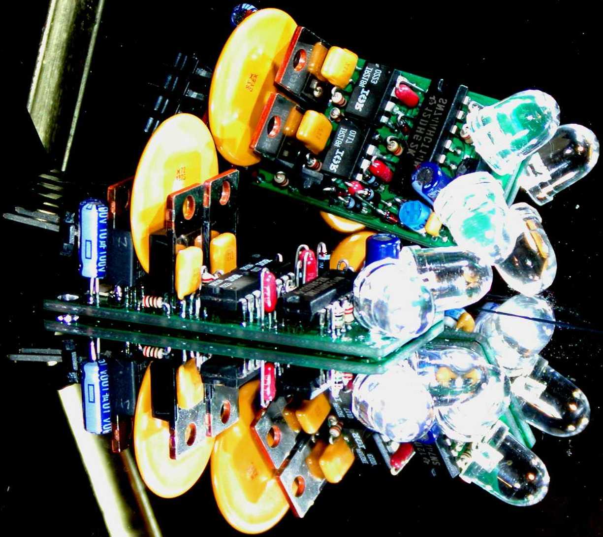
c3schematic
LED3XS24 "c" Schematic
c3timing
LED3XS24 "c" Timing Diagrams. Note! Not to scale.
Assume the period is 60 seconds with a duty cycle of 33%.
c1layout
LED3XS24 "c" Layout
This layout is for the "c1" revision but the "c3" is nearly the same.
 RED ROCK LED3X - Solar Tracker Circuit KIT - Assembly and test. Tom made this cool YouTube on assembling an LED3XS24Vc3PKIT. Thanks Tom
"c3"/"c1" Assembly Instructions:
   LED3 Bicolor surface mount LED, the black band is away from
               the board edge.
   R13 2.4K    1 watt resistor (4.8K 2W  for 48V
               I use 2 of the 2.4K resistors in series.)
   D1  1N4148  horizontal diode
   D2  1N4148  horizontal diode
   R8  220 ohm horizontal resistor (May be 200 ohm.)
   R9  220 ohm horizontal resistor (May be 200 ohm.)
R5 1M Potentiometer ("c3 revision" has a surface mount part.)
C3 .02uF Capacitor (Change to .1uF and place between the emitter
and collector pins of Q5 for the ReMote sensor version.)
R10 10K If used (For Remote Shut down feature.)
D9 1N4148
D10 1N4148
D6 5.1V Zener
C9 .1uF Capacitor
D7 5.1V Zener
D8 1N4148
R3 910 1/8W Resistor
C5 .1uF Capacitor
R11 10K If used (For ReMote sensor version, 10K with normal short leads.)
R12 10K If used (For ReMote sensor version, 10K with bent leads.)
CONN2 If used (For ReMote sensor version and solder in place.)
R2 180K (Change to 2.2M for ReMote sensor version.)
R1 1M
D3 5.1V Zener
R4 470K or 510K for "c3 revision" (was 47K in "c1 revision")
D4 1N4148 Diode
C10 .1uF
R7 200 ohm 1/8W Resistor (May be 220 ohm.)
C4 100uF 10V Electrolytic Capacitor. Observe the polarity.
The stripe is Minus.
R14 10K 1/4W Resistor (17K 1/4W for 36V version, 27K 1/4W for 48V version.)
Note! It's easy to get this resistor placed incorrectly into a large
via used to connect the top and bottom sides of the board. Don't use
this via. The correct holes both have fine traces to them on the top
side of the board.
Note! R14 may be a 1/2W unit. If it is 1/2W see the special
installation instructions for R6.
R6 200 ohm 1/8W Resistor (May be 220 ohm.)
Note! If R14 is a 1/2W type orientate R6 180° from that shown
in the parts layout drawing. I.e. the body of R6 is away from the
body of R14.
D5 51V Zener Diode ("c3 revision" has D5 mounted near mounting hole.)
(Don't place if this is a ReMote sensor version, instead place the small connector CONN2.)
Note! My vender for these pots, Panasonic, made a change so there are no stops at the ends anymore.
I have added a red dot as a pointer on the pot. Here is a picture that represents the pot face.
apply current limited power to CONN1, +18 volts between pin 1 + and pin 4 -, and test for:
About  5V on U3 pin 14
About  5V on U1 pin  8  Note! U1, and U2 pins 8 will have about 5V
About  5V on U2 pin  8  since Q6 hasn't been installed yet.
                        Current will pass through R14 and D3, D6, and D7
                        resulting in about 5V on VCC
About 15V on D7 pin  C  and about 15V across the Zener string.
                        Then current will pass through R3 resulting
                        in about 5V on VDD and U1, and U2 pins 8.
apply current limited power to CONN1, +18 volts between pin 1 - and pin 4 +, and test for:
About  5V on U3 pin 14
About 15V on U1 pin  5
About 14V on U1 pin  8  Note! U1, and U2 pins 8 will now have about 14V
About 14V on U2 pin  8
apply current limited power to CONN1, +18 volts between pin 1 + and pin 4 -, and test for:
About   5V on U3 pin 14
About 4.5V on U1 pin  2
About  0V on U1 pin  1
About  5V on U2 pin  1
About  5V on U1 pin  1
About  0V on U2 pin  1
Observe the change on U1 pin 1 and U2 pin 1 when the light is moved in front of the sensor LEDs.
C2 47uF 50V Electrolytic Capacitor. Observe the polarity. The stripe is Minus. Was 1uF in the diagram. (Actually this capacitor is quite non critical and may be 22uF and with other voltages, 16V or higher.)
C1 47uF 50V Electrolytic Capacitor. Observe the polarity. The stripe is Minus. Was 1uF in the diagram. (Actually this capacitor is quite non critical and may be 22uF and with other voltages, 16V or higher.)
apply current limited power to CONN1, +18 volts between pin 1 + and pin 4 -, and test for:
   Vin volts on CONN1 pin 2.
       Note! Vin will be less than the power supply
       due to the current limiting resistor.
   0   volts on CONN1 pin 3
       The indicator LED should be Red.
   Shine light onto Western LED1
   0   volts on CONN1 pin 2
   Vin volts on CONN1 pin 3
       The indicator LED should be Green.
Observe the change on CONN1 pin 2 and CONN1 pin 3 when the light is moved in front of the sensor LEDs.
The indicator LED should go out.
This tests for under voltage protection.
Note! This test on some units may fail. This is not a true failure. You may need to connect a light load to CONN1 pins 2 and 3. A 100 ohm resistor or small 12V motor should do the trick.
Make sure they stop the motor before encountering a hard mechanical limit as excessive current can occur. The forces can be quite high and cause mechanical damage if the limit switches are not properly adjusted.
I have a customer who didn't do this and in the morning he had 3 broken PV panels. This was an expensive lesson, make sure the switched are set properly.
Adjust the potentiometer counter-clockwise to 1/2 to 1 Seconds.
The motor should move in bursts determined by the setting of the potentiometer. The standard duty cycle capacitor, 100uF, gives a period of about 50 seconds. This has a loose tolerance as this capacitor is an electrolytic type. Usually -20% to +80%. This capacitor can be made as high as 1000uf to increase the cycle and on times to about 5 minutes if desired. (But I don't recommend this.)
On an individual basis the capacitor could be quite a bit larger, however, capacitor leakage currents in combination with input trigering currents on the 74AHCT14 may not allow the circuit to oscillate.
Step 24. Mount the tracker inside a weather dome. Use a #4 machine screw. Make sure there are no shorts. I use  plastic peanut butter jars. They seal quite well. The
Reverse Inhibit or Limit Switch installation.
OK, I don't really use these time consuming assembly procedures when I put them together. If you are very experienced you may want to do it the way I do it.
Works very nicely %^)
The LED3X requires a weather dome to protect it from the weather, moisture, and insects. I recommend small
I have tried and like using plastic Jiff Peanut butter jars, which are made from
Jiff peanut butter jar.
Ok, the tracker in these images is not the LED3X but the concept is the same.
Jiff peanut butter jar with only the lid.
See Walter's ideal picture of this:
The exception is when the No-Park feature is installed on remote sensor versions. No-Park trackers usually need "Slip Rings" to transmit power down the tracking mount without twisting off the wires.
Parking is the action, generally, to move to the Eastern limit switch (or South for Dual Axis trackers) when it gets dark. Usually this happens when the sun goes down. However, parking can happen when there are dark storm clouds or when you simply put your hat over the sensors.
I.e. the tracker does not have to cycle all the way back to the limit switches.
Dual Axis Solar Tracker Setup:
Definition of "Polar Axis".
The Earth revolves about an axis called the "Polar Axis" which in the northern hemisphere is aligned closely to the "North Star".
The sun also appears to rotate about this axis.
Definitions of "True Polar Axis" vs. "Pseudo Polar Axis".
There is a very nice explanation of how to setup "True Polar Axis" mounts for satellite dishes.
Solar applications are essentially the same.
signals
See the Satellite Signals web page:
"Explanation of satellite antenna polar mount"
Polar Mounts
Polar Example 1
Polar Example 2
Polar Mount 5
and others on the page.
Thank you Satellite Signals!
Satellite Dishes on Wikipedia
Some satellite dish mounts are designed to be moved purely manually. These generally don't have the "Offset" adjustment. Without the offset adjustment these can only be used for "Pseudo Polar Axis" mounts.
dish
Parabolic Dish
Some specs on dishes in general.
Polar Mounts on Geo Orbit
Dish      Focal   Image  Real
Diameter  Length  Diam.  Diam.  F/D
C-Band (The Big Dishes)
 6' 1.8m  ?       ?      ?      ?
 8' 2.4m  36"     0.36"  3.5"   0.40
10' 3.0m  48"     0.48"  4.25"  0.40
12' 3.7m  51"     0.51"  4.5"   0.48
KU-Band (Direct Broadcast)
?   ?    ?        ?      ?      ?
"Focal Length" is the distance along the Radix of the parabole.
"Image Diameter" is the focal zone diameter if the parabola were "Perfect".
"Real Diameter" is the focal zone diameter of "Practical" dishes.
"F/D" is the ratio of Focal Length / Diameter. This describes the "Flatness" of the dish.
wind
Wind Loading.
(Speedmph * .0237)³ = lbs/ft²
However, it would be nice to record high winds if they do occur. Here is an excel spreadsheet that calculates the parameters of a simple and reliable type of one shot wind sensor I call a "Ball On Pipe Wind Sensor".
led3xforsale
LED3XS24Vc3 For Sale
1. ReMote sensors, single or dual axes
2. High drive voltages
3. No-Parking
4. Reverse Inhibit for fast motors drives
5. Remote Shutdown for things like thermostatic over temperature controls
6. Limit Switches with Normally Open contacts.
Shipping & handling is $4.00us for any number of trackers or devices in the US.
Shipping & handling is $10.00us for any number of trackers or devices in the outside the US
to almost anywhere in the world.
I accept checks, money orders, and funds in "US DOLLARS ONLY".
Make checks payable to "Duane C. Johnson".
Use Western Union:
http://www.westernunion.com/Home
Just email me the Western Union Money Transfer Control Number (MTCN).
If you entered a query question please give me the correct response answer!
The part numbers and the quantities of what you want me to send to you.
Jamaica
Mexico
Packages just get "lost".
Use FedEx, UPS, or DHL at about $95us for 6 day service.
Or a private shipping service in the US.
I call these "Smuggler Address".
Many times Canada takes 6 weeks, especially British Columbia.
What are you building?
Be very specific.
Got any pictures?
What is the tracking mount type?
Vertical axis, AZimuth/ALTitude? (Generally not recommended)
Horizontal axis? (Usually for parabolic troughs, or LFRs(Linear Fresnel Reflectors))
Polar axis, Right ASCension/DEClination? (The best)
Possibly a Heliostat mirror?
What is being tracked?
PV Panels?
Thermal Panels?
Dish or Trough Concentrators?
What motors are you using?
How fast do they move?
How much time to move 180 degrees?
How much power do they take?
How much current do they consume?
Where are you located?
The Longitude?
The Latitude?
Postal Address:
Duane C. Johnson
Red Rock Energy
12181 375th St.
North Branch, MN
USA 55056-6799
Duane C. Johnson <redrok@redrok.com>
(651)583-2265 days and evenings. Central time zone.
Part Number
LED3X Solar Trackers For Sale
Cost
sellled3xs24vc3p
LED3XS24Vc3P
Standard Single Axis Solar Tracker with Parking$35us
sellled3xs24vc3pkit
LED3XS24Vc3PKIT
Standard Single Axis Solar Tracker KIT with Parking$20us
sellled3xs24vc3rip
LED3XS24Vc3RIP
Standard Single Axis Solar Tracker with Reverse Inhibit & Parking$45us
sellled3xs24vc3ri12
LED3XS24Vc3RI12
Standard Single Axis Solar Tracker with Reverse Inhibit, & 12 Pigtails +Red, Yellow, Blue, and -Black$45us
sellled3xs48vc3rip
LED3XS48Vc3RIP
48 Volt Single Axis Solar Tracker with Reverse Inhibit & Parking$50us
sellled3xs24vc3ripkit
LED3XS24Vc3RIPKIT
Standard Single Axis Solar Tracker KIT with Reverse Inhibit & Parking$30us
sellleddrm24vc3pppack
LEDDRM24Vc3PPPack
Standard Dual Axis Solar Tracker with ReMote sensor, & Parking on both axes$90us
sellleddrm24vc3pppackkit
LEDDRM24Vc3PPPackKIT
Standard Dual Axis Solar Tracker KIT with ReMote sensor, & Parking on both axes$60us
sellleddrm24vc3ripppack
LEDDRM24Vc3RIPPPack
Standard Dual Axis Solar Tracker with ReMote sensor, Reverse Inhibit, & Parking on both axes$110us
sellleddrm24vc3ripppackkit
LEDDRM24Vc3RIPPPackKIT
Standard Dual Axis Solar Tracker KIT with ReMote sensor, Reverse Inhibit, & Parking on both axes$80us
sellledsrm24vc3ppack
LEDSRM24Vc3PPack
Standard Single Axis Solar Tracker with ReMote sensor, & Parking$45us
sellledsrm24vc3rippack
LEDSRM24Vc3RIPPack
Standard Single Axis Solar Tracker with ReMote sensor, Reverse Inhibit, & Parking$55us
sellledsrm24vc3rinpack
LEDSRM24Vc3RINPack
Standard Single Axis Solar Tracker with ReMote sensor, Reverse Inhibit, & No Parking$55us
sellledsrm48vc3rippack
LEDSRM48Vc3RIPPack
48 Volt Single Axis Solar Tracker with ReMote sensor, Reverse Inhibit, & Parking $60us
sellleddrm48vc3ripppack
LEDDRM48Vc3RIPPPack
48 Volt Dual Axis Solar Tracker with ReMote sensor, Reverse Inhibit, & Parking on both axes$120us
sellledsrm24vc3ppackkit
LEDSRM24Vc3PPackKIT
Standard Single Axis Solar Tracker KIT with ReMote sensor, & Parking$30us
sellledsrm24vc3rippackkit
LEDSRM24Vc3RIPPackKIT
Standard Single Axis Solar Tracker KIT with ReMote sensor, Reverse Inhibit, & Parking$40us
sellledsrm24vc3rinpackkit
LEDSRM24Vc3RINPackKIT
Standard Single Axis Solar Tracker KIT with ReMote sensor, Reverse Inhibit, & No Parking$40us
sellledsrm24vc3rinpackkit
LEDSRM24Vc3RINPackKIT
Standard Power unit with Reverse Inhibit, & 12 Pigtails +Red, Yellow, Blue, and -Black$40us
sellri
RI
Reverse Inhibit Module$10us
sellls
LS
Normally Open Limit Switch Module for use with Normally Open, NO, switches
Note! Not recommended as its not "Failsafe".$10us
sellrils
RILS
RI & LS Module
Again, Not recommended as its not "Failsafe".$15us
sellsarms
SARMS
Single Axes ReMote sensor Module.
Specify if "Parking" or "No Parking" is desired?$10us
selldarms
DARMS
Dual Axes ReMote sensor Module.
Specify if "Parking" or "No Parking" is desired and on which axes?$20us
limitops
How Limit Switches Operate
Limit switches are essential for servo motor operation with solar trackers. I made this diagram to help explain how they work.
Middle. The left limit switch has opened to stop movement to the left. To move to the right again the diode conducts current that allows movement to the right.
Bottom. The right limit switch has opened to stop movement to the right. To move to the left again the diode conducts current that allows movement to the left.
 This is a nice limit switch at Burdens Surplus Center and other sources.
This type of switch is often called a "Refrigerator Light Switch".

Limit switches can be used in combination with a "Normally Closed" type thermostat. These thermostats "Open" when the temperature is greater than the set point. This circuit assumes the thermal storage can absorb the heat delivered to the storage for the time it takes the sun to move sufficiently of axis to reduce output.
Another method is to use a thermostat with the Remote Shutdown option to prevent over temperature conditions.
Some have expressed an interest in driving high powered loads, more than 10A or so, beyond the capabilities of the H-Bridge driver transistors. To this end I developed several high powered driver circuits using relays, (actually their almost the same circuit as in the relay trackers Relay, Led1, Led2).
 RelayDC1
Relay circuit that uses DC relays. The DC motor in this case is a permanent magnet DC type which is reversible. The capacitors are used to prevent relay chatter. The value must be tested with your relays. The value may range from 10µF to as much as 1000µF depending on the relay characteristics.
Stick with solid state circuits which don't have a wear out problem.
 RelayAC1
Relay circuit that uses AC relays. The AC motor in this case is a capacitor run type.
 RelayAC2
Relay circuit that uses AC Solid State relays with 3 to 32 VDC control inputs. The AC motor in this case is a capacitor run type.
 LED3XManual
Some have expressed an interest in adding a switch to manually move the array for test or cleaning. One of these circuits, when added between the tracker and actuator, will allow manual movement.
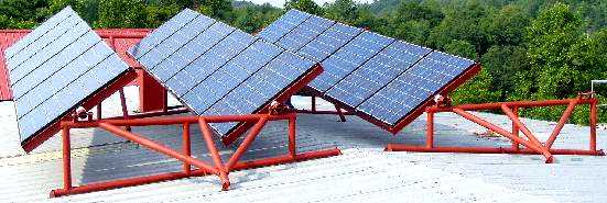
rowe
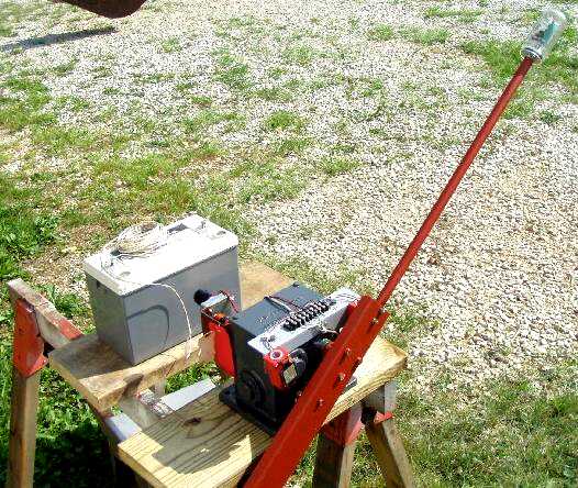
Patrick Rowe's system based on the Solar Resources International SOL R BEAM thermal parabolic trough
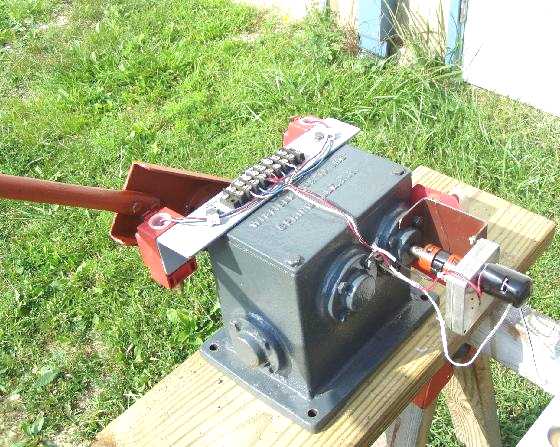
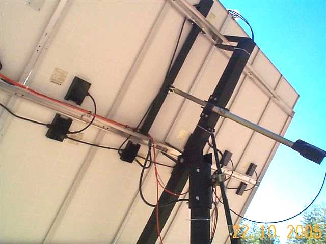
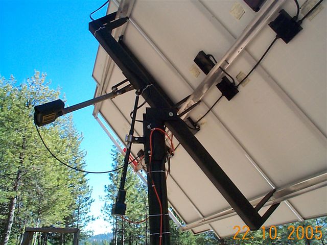
Patrick Rowe is using an LED3XS24Vc1RM variant. It has an external LED sensor. This tracker is driving an American Science & Surplus DC gear motor. In this case the gear motor is being tested for use with a trough solar hot water heater. I believe the motor turns at 1.6 RPM and consumes 300mA @ 12V.
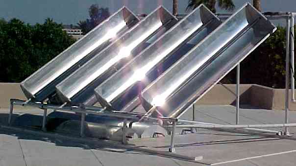
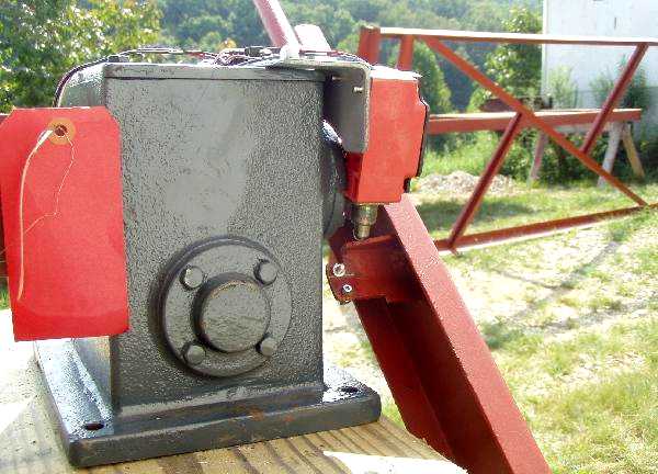
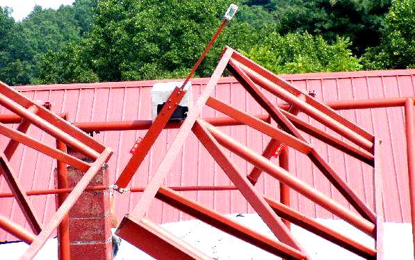
The commercial trough on which the LED3X is installed. The original tracker had given up the ghost several years before. The four troughs are mechanically linked together.
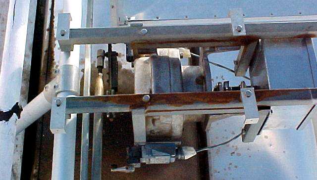
The Motor is in the box on the right with a gear reduction in the center with the crank and linkage on the left.
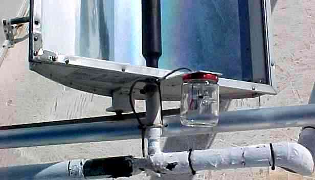
Insulated hot water piping and what looks to be a Kee Klamp frame. See:
 Kee Klamps
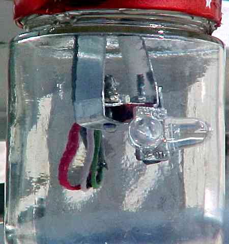
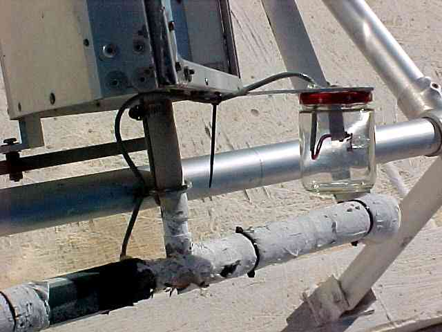
The glass baby food jar weather dome.
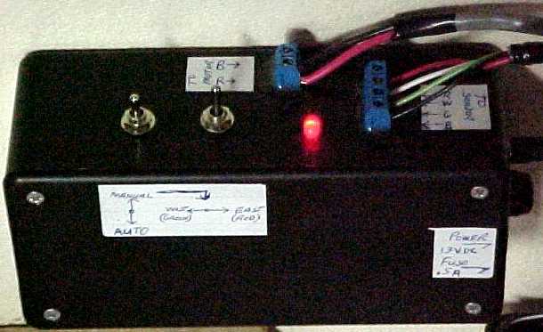
The control box which contains the LED3X and switches for manual operation.
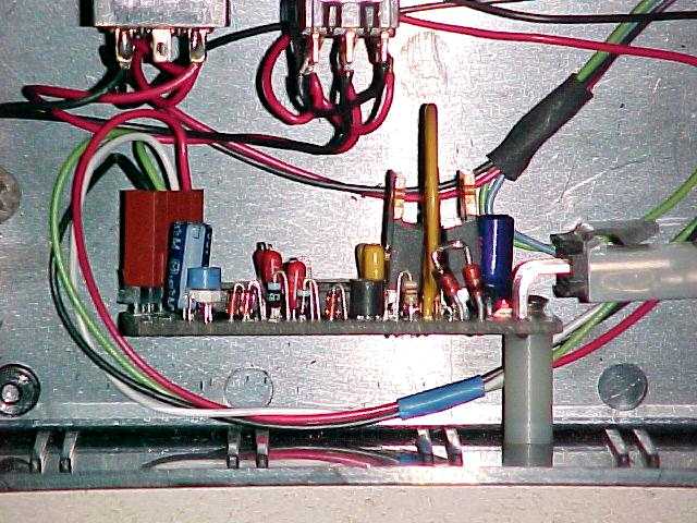
Interior of the control box.
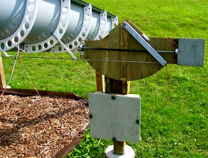
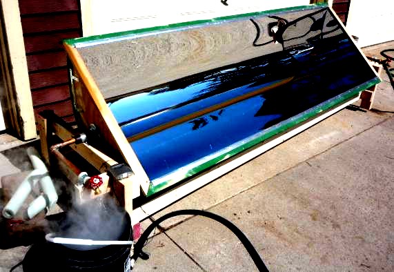
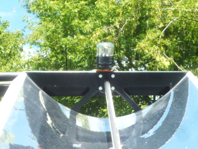
plhak
George Plhak's N-S Axis Parabolic Trough Tracking Mount
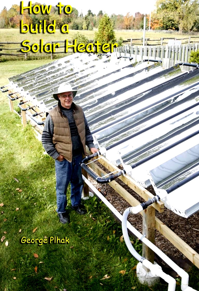
![]()
Note! This animation is of an earlier revission.
(It has a different weather dome and motor drive.)
The cover is a Leviton
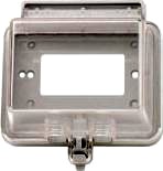 5997-CL. George polished out the raised lettering to improve the optical properties.
* George Plhak's Web Site.
<George Plhak>
Ron Smith's N-S Axis Parabolic Trough Tracking Mount
These 4 units will raise the water temp 20°F at 2 gallons per minute flow."
2gal/min*8.35lb/gal*20°F*60min/hr=20028BTU/hr
Which is:
20028BTU/hr*0.29307Whr/BTU=5870W
Jim Britton's parabolic trough
Jim is making a parabolic trough solar powered refrigeration system.
<jbritton@dslextreme.com>
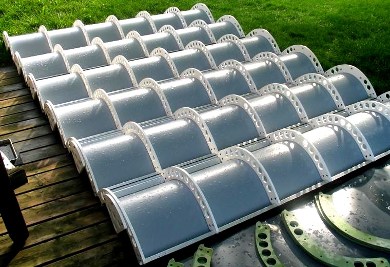
Paul Soucy's Environmental Solar Systems parabolic troughs
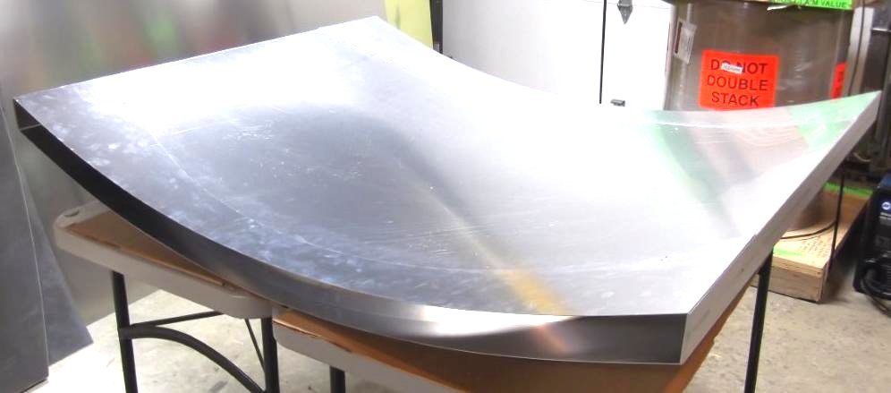
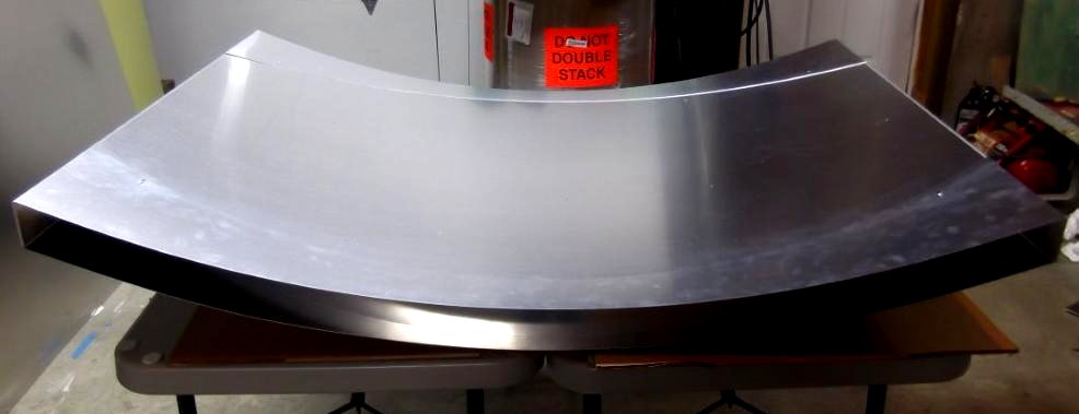
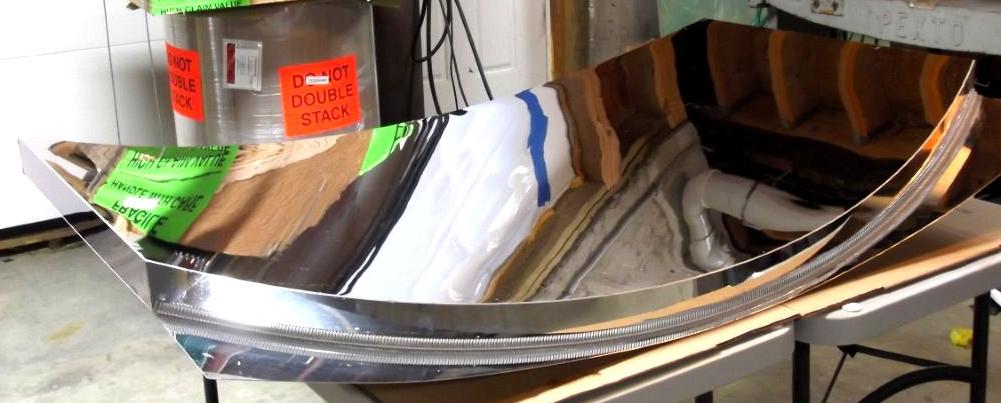
Paul of Environmental Solar Systems makes a line of parabolic trough reflectors.
They are selling this in several sizes.
He is intending this for the DIYer who wants to make their own tracking mount and receiver.
This version is 15.97ft² in area, but other sizes can be made.
The first 2 images are intended to have reflective films applied to the surface.
The third image has an anodized reflective surface.
I estimate the thermal power output to be about:
16ft²*80W/ft² = 1280W thermal before losses.
http://www.environmentalsolarsystems.com
<envsolar@comcast.net>
Mike Grabon's Parabolic Trough
Here at Solar Mountain Energy, we have a low cost parabolic concentrator with a fifteen square foot aperture. Our unit has a copper receiver with a selective radiation surface and a static vacuum encasement. In a 3.5ft by 6ft, 21ft², Lexan covered package it weighs in at 25 pounds. It will heat 30 gallons of water 100°F in 5 hours, or create steam.
I estimate the thermal power output to be about:
21ft² * 80W/ft² = 1680W thermal before losses.
They offer them for $450.00 per unit.
$450 / 1680W = $0.27/W
$450 / 21ft² = $21/ft²
Unfortunately, I think this guy has disappeared.
http://solarmtn.com
<solar.mountain@yahoo.com>
<solarmtn@aol.com>
Basic Solar Collector Thermodynamic Calculations
I have an Excel spreadsheet that may be useful for calculating the performance of solar collectors and collectors in combination with heat engines, especially Rankine or Steam engines.
SolarCollectorThermodynamics01.xlsx
1. I have included the steam formulas for converting between temperature and pressure. Now the formulas can use a variety of fluids other than water. Any fluid which has the "Antoine Equation" parameters can be calculated.
2. Useful for all flat plate collectors.
3. Useful for Concentrators such as Troughs, Dishes, Heliostats, and Linear Fresnel Reflectors.
4. Calculations for PV Panels vs. panel operating temperature. Also shows the rejected heat from the panel which is useful in understanding cooling requirements. Rejected heat could be used for domestic water heating.
If not this version is in ".xls" format for Excel 97 to Excel 2003.
SolarCollectorThermodynamics01.xls
If you don't have Excel you can get a free version from WPS Software.
Lee's Vertical Axis Flat Panel Water Heating Tracking Mount
Shadowing Calculations.
Here is an Excel spreadsheet to do some Shadowing Calculations.
Note! While I have tried to be accurate these calculations may not be fully rigorous.
Also the latitudes and angles are basically for the northern hemisphere.
sel
backtracking
SET, Solar Energy Technologies
was Sedonia Energy Labs
 http://sedonasolartechnology.com
InteliTrack
http://sedonasolartechnology.com
InteliTrack
They have a horizontal East/West mounted array of PV panels.
Note! The shadowing is fairly severe so the ROTation, East/West, motion is quite limited.
They could get more energy return if oriented North/South, mainly by the reduction of shadowing effects. They prevent shadowing by employing a concept called "BackTracking" motion at the ends of the day, effectively making the array more closely resemble a "Stationary" array. Stationary arrays have sever "Cosine Losses" in the early morning and late evenings.
( Yes, in the past I've written against this because panels were expensive.)
The extra panels will be cheaper than the cost of the East/West motion mechanism. Today this orientation, as SET described, just doesn't make sense anymore.
Adjust the spacing to prevent shadowing at solar noon on the winter solstice. Backtracking would never be needed.
However, backtracking of the SET mount wouldn't be needed with a North/South orientation.
Scorpius Trackers
![]()
![]()
![]()
Now these guys, as opposed to SET, know how to orient their "Horizontal North/South Axis" system properly. This is for a large utility sized array where they are packing a lot of panels into a given area.
Very cool!!!
However, I suspect there may be problems under high winds where vortex shedding may cause oscillations. Especially if a resonance is encountered.
Andra Loonstra's "Horizontal North/South Axis" with Tilted Panels"


An Epicycloid Bearing
Red in this image is the cable or tension bands. Notice how the upper circle rotates 180° while only going 90° around the lower circle. This arrangement is also used to effect the bisector motion in the "Receiver Axis Heliostat" designs.
There is a bit of a problem with the above diagram for use in solar tracking mounts.
It's out of balance, just as in the satellite dishes. It would be better if the rolling part rolled under the stationary part like this:
And since it need only rotate 180°:
Some youtube videos using my trackers.
djpitrut
djpitr made a YouTube video showing his system.
Tracking throughout the day
A heliostat in the works
bomba
bomba244's Tracking Chair
scrapit85 made a YouTube video showing his system.
windysolar
windysolar1's Vertical axis mount. Part 1
windysolar1's Dual Axis Vertical axis mount. Part 2
windysolar1's Dual Axis Vertical axis mount. Part 3
windysolar1's Dual Axis Vertical axis mount. More
gray
Andrew Gray is building a multi trough parabolic water heating array. Part 1
Andrew Gray doing some testing. Part 2
Andrew Gray mounted one element in the frame. Part 3
Andrew Gray rearranged the frame to a North/South orientation. Much better! Part 4
Andrew Gray has completed 2 of the troughs and the embedded computer control system that keep them aligned with the sun. Part 5
Andrew Gray has them all done and ready to be mounted on the roof. Part 6
sportsmandave
Sportsmandave's Single Axis Pseudo Polar Axis C-Band Satellite dish mount.
Roberts
Paul Roberts's Single Axis Pseudo Polar Axis mount.
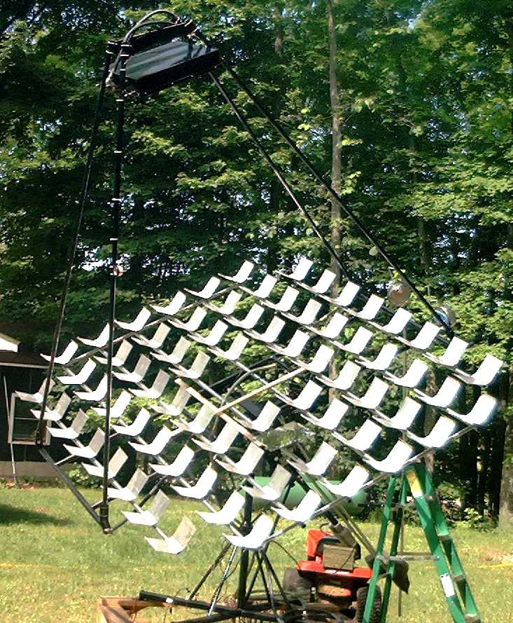
Andrew
Andrew Thompson's Array of Vertical Axis mount.
This is an amazingly large array of tracked PV panels. Each mount is rotated with cables from a central drive mechanism. A single LED3XS24Vc3P tracker drives a Suzuki windshield wiper motor. The gear reduction train is made from a string of bicycle derailleurs and a large plywood final "Not A Sprocket". Very Cool!!
Andrew is having a bit of a tracking problem when starting up in the morning.
1. It was parked in the east overnight.
2. When the sun comes up it heads to the west and is stuck there for hours.
3. If manually positioned to aim at the sun it tracks fine.
All that light blocking tape was an experiment which didn't really work.
Andrew now tried a "Gate" using a black paper card between the sensors. While this is an improvement I suspect this may not work at all times of the year.
I think the problem is caused by having the tracker located behind the front row of PV Panels to the south. The backside is white and highly reflective. The tracker can get confused by the bright reflections.
My suggestion is to mount the tracker on top of the middle PV Panel to the south and not use the tape nor the gate.
Andrew has moved the tracker to the top of a panel in the front row eliminating the earlier problems. Watch the system searching for the optimal direction.
Andrew describes in more detail about why there were tracking problems with the tracker mounted low down on his large "Not A Sprocket" drive wheel.
He also describes a fix for his out of round "Not A Sprocket".
See: thompson
fearlessthinker
RED ROCK LED3X - Solar Tracker Circuit KIT - Assembly and test. Tom made this cool YouTube video showing us how to assemble an LED3XS24Vc3PKIT. Thanks Tom!
canbe
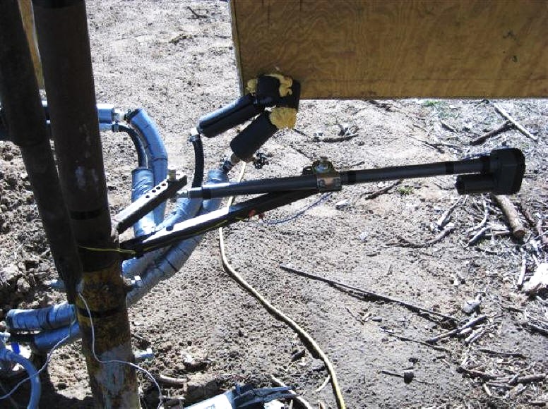
Tightas Canbe: demonstration of LED3X driving a linear actuator. Solar tracker for satellite dish mounted solar panel array
Tightas Canbe: Solar Array on a not-so-sunny day
Tightas Canbe: Solar Day January 23 2016
Tightas Canbe: Solar tracker for second array now installed and working
Tightas Canbe: Solar Array Number Two
Tightas Canbe: Solar PV
Tightas Canbe: Solar Pot Roast
Tightas Canbe: Solar Squash
Tightas Canbe: Doubt the power of the sun?
Paul Pakelson's system
I did not supply the tracker for his tracking mount but it is a nice example. Thanks paul for the picture.
Bernie Lancette's PV Array Tracking Mount
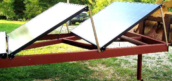
A very nice example of a PV tracking array.
The gearbox is made by Winsmith Inc. It's a double worm gear type with a gear ratio of 2000/1. I could not find it on their web site though.
Solar PV tracker, as featured in an Instructable.
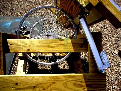
This is an interesting tracking mount based on bicycle wheel rims for use as the bearings.
This tracking mount is described in an Instructable. See:
The Instructable
Solar_PV_tracker
.PDF of The Instructable
bwitmer_Solar_PV_tracker.pdf
The tracker needs to be mounted on the panel and not on the vertical pole as in bwitmer's instructions.
I have tried several times to get him to edit this Instructable but he hasn't done it yet nor has he returned my messages. I gave up.
Also, if the small linear actuator is used, which is probably in the "Fast" category, the
LED3XS24Vc3RIP $45us plus shipping tracker with reverse inhibit feature should be used with these fast motors.
However, I would not recommend the use of linear actuators for this tracking mount!
The rim is basically a large diameter pulley, what could be better?
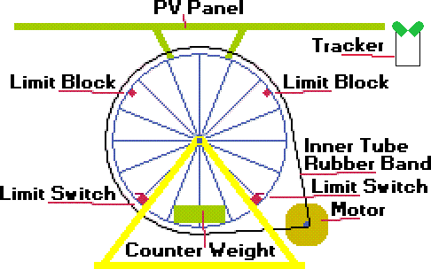
Rotary Motion Concept for use with this Instructable.
Use this motor:
| Burden Sales Surplus Center
| http://www.surpluscenter.com
| 2 RPM 12 VDC GEARMOTOR $15
| http://www.surpluscenter.com/item.asp?item=5-1763
Or the Dayton 2L003 gearmotor from Graingers.
Or use the large red rubber inner tube protector as shown in his images.
Wolfgang Schmidt's tracking system on a boat deck
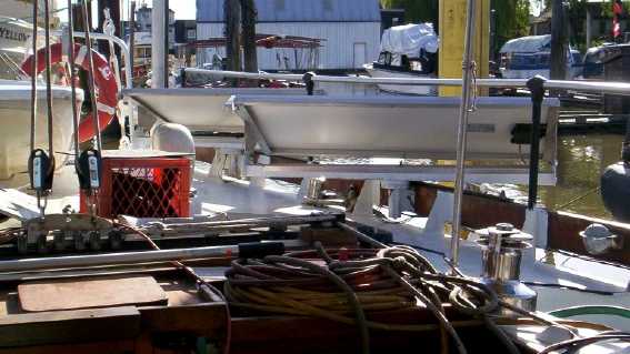
Wolfgang <wschmidt@smartt.com>
is making tracking solar panels for boats. He plans to sell them. Neat huh!
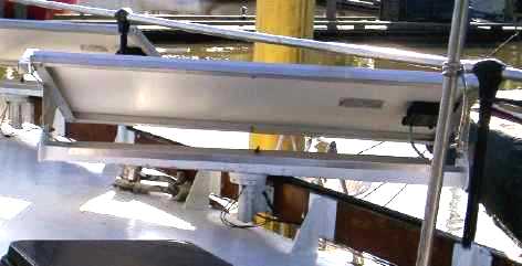
The vertical axis mount can turn 360°s. They are equipped with slip rings to bring the power to the boats battery charging system.
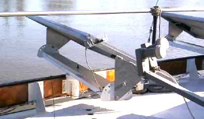
The solar trackers are the LED3XS24Vc1NP, $40us. These have been modified with the "no park" feature, (see below). This was required as the orientation of the boat changes constantly.
fitch
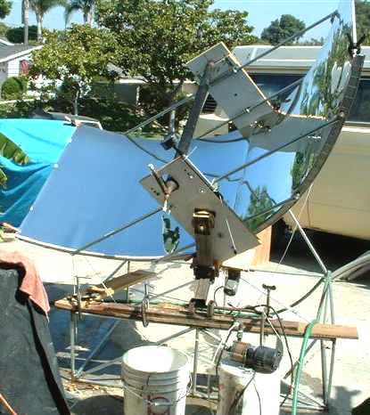
Fresnel Dish
What the William Fitch's Fresnel Dish looks like before mirrors are added.
This is ????'s version of the
Teton Engineering / Mother Earth News Fresnel dish.
I have a copy of the The Mother Earth News version here:
tmen
 * The TMEN article.
evacuatedtube
* The TMEN article.
evacuatedtube
William Fitch's Evacuated Tube Polar Axis Mount
William Fitch is using an LED3X on an evacuated tube water heating panel.
Bill's power supply is a simple 24V transformer, 4 diode bridge, and large capacitor.
He had problems burning actuator brushes. I recommended he use the center tap on the secondary
to reduce the peak voltage from about 34V to 17V.
http://www.WeAreSolar.com
<William H Fitch III>
Vincent Martinez's Test Tracking Mount
Vincent made a mock-up using two car rear view mirror electrical motors plus a few plastic gears.
This was a test for him to become familiar with the equipment before fit it on the real big one in three years or so.
The tracker version he is using is the LEDDRM24Vc3PPPack, a dual axis tracker with a ReMote sensor head. Notice the shadow blocker.
<vincent.mrtnz@hotmail.fr>
Solar Tony's Weather Dome
Solar is using a Glass Hazardous Environment light fixture for his weather dome.
You can see the dual axis remote sensor with its shadow blocker.
The tracker version he is using is the LEDDRM24Vc3PPPack,
a dual axis tracker with a ReMote sensor head.
John Theismann's Small Pseudo Polar Axis Tracking Mount
This is a very nice example of a pseudo polar axis mount. The basic mount is built with threaded water pipe and 45° elbows. The drive motor is a Grainger's 2L003 gearmotor with 7000/1 gear ratio. The final gear ratio is about 8/1 for a total of about 56,000/1. Note, the final gear is made from a 180° segment of an internal gear ring. OK, I would like it longer but John says it works nicely with the standard LED3XS24Vc3P running on 12V.
John has a pair of limit switches to limit the mechanical travel. He also has manual motion switches for experimental purposes.
John has a homemade wind generator.
<John G Theismann
John originally had an <MTM Scientific> tracker but it didn't work well so he got mine instead.
Kevin Moore's Tracking Mount
Kevin's found some very nice looking sidewalk lighting units that can be a bit modified to be used as weather domes. There was a kind of pagoda structure that was cut off. There is also a nice weather tight 1/2" threaded EMT port on the bottom.
Nice work!
Christopher Hoskin's Tracking Mount
Christopher wrote:
Douglas Hutchinson's Machined Lexan Weather Dome
Very nice weather dome. This is machined in 2 halves and bolted together. He will be casting the next blocks using acrylic casting resin to form the space needrd for the LRDDRM dual axis sensor.
Dan Lenox's Pseudo Polar Axis Solar Build Chronicle
Briery Mountain Enterprises, LLC
Dan Lenox has developed a nice pseudo polar axis solar tracking mount.
He has extensively documented his build on his website.
He is using one of my single axis LED3X solar trackers.
<dlenox@briery.com>
http://www.briery.com/solar/index.html
Here is a full discription of how Don built this:
http://www.briery.com/solar/solar_tracker.html
Gary Witherspoon's Dual Axis Tracking pseudo polar axis Mount
Gary Witherspoon builds dual axis tracking mounts commercially.
These are Dual Axis Tracking pseudo polar axis Mount designs.
He uses my LED3X series of trackers to control them.
Please contact him for pricing. <garyrw@direcway.com>
Ed Pezant's Dual Axis Tracking pseudo polar axis Mount
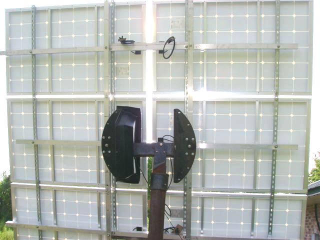

Ed has an Enphase Energy data logger.
Click this link and see how he's been doing.
Walter Carmens's Single Axis Tracking pseudo polar axis Mount
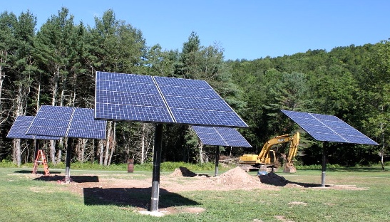
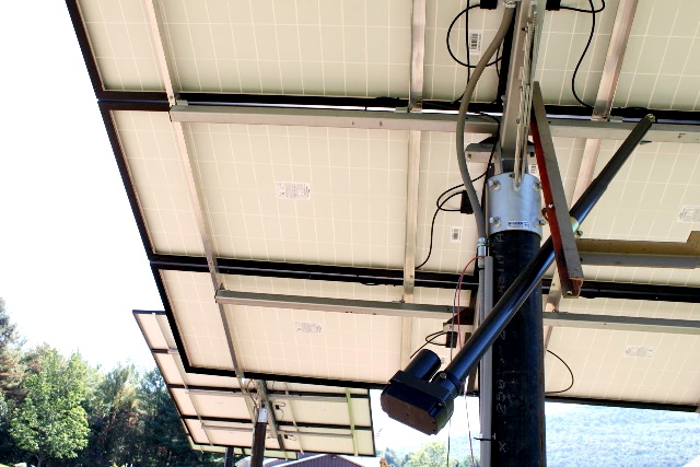
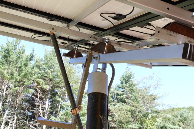
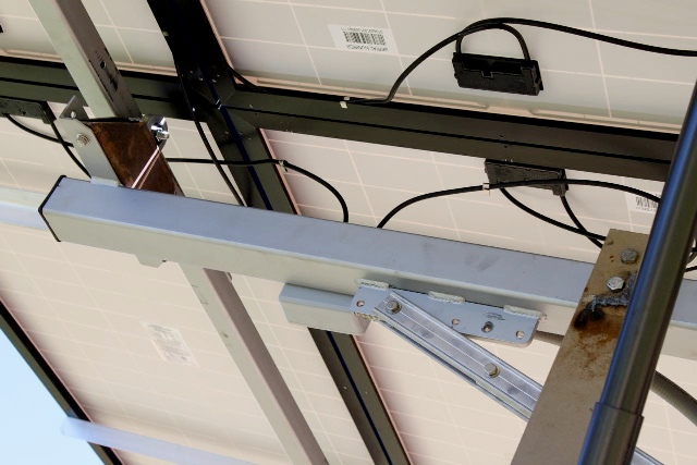
Walter modified a fixed PV panel mounts by Power-Fab.
Note, how he added pivots on the ends of the pseudo polar axis main bar.
This allows the PowerTech QARL-2436 (HV-36) linear actuator to move the panels in Right Ascension (directly follows the path of the sun).
Henry Boschen's Single Axis Horizontal Mount
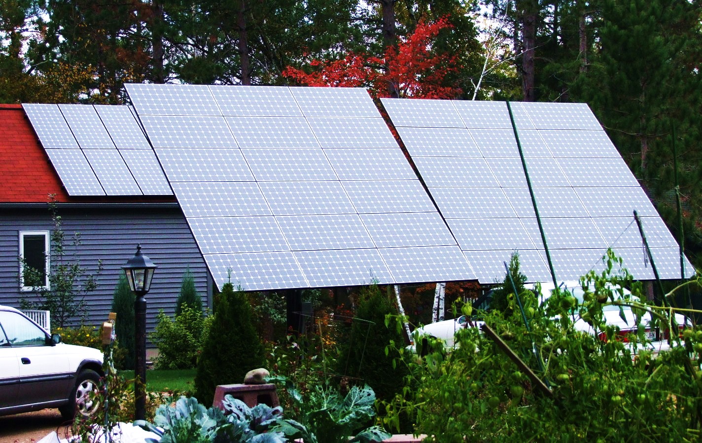
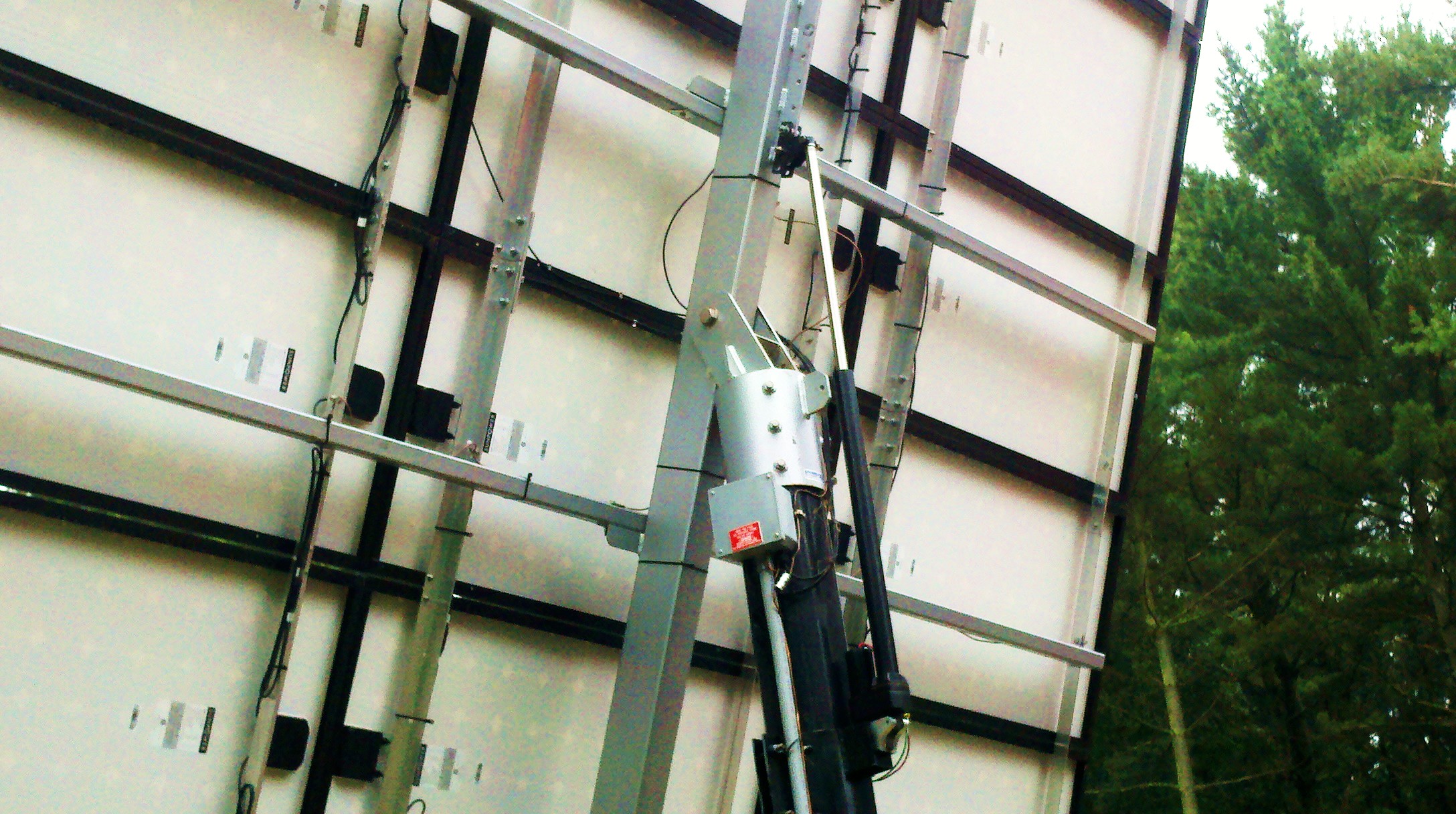
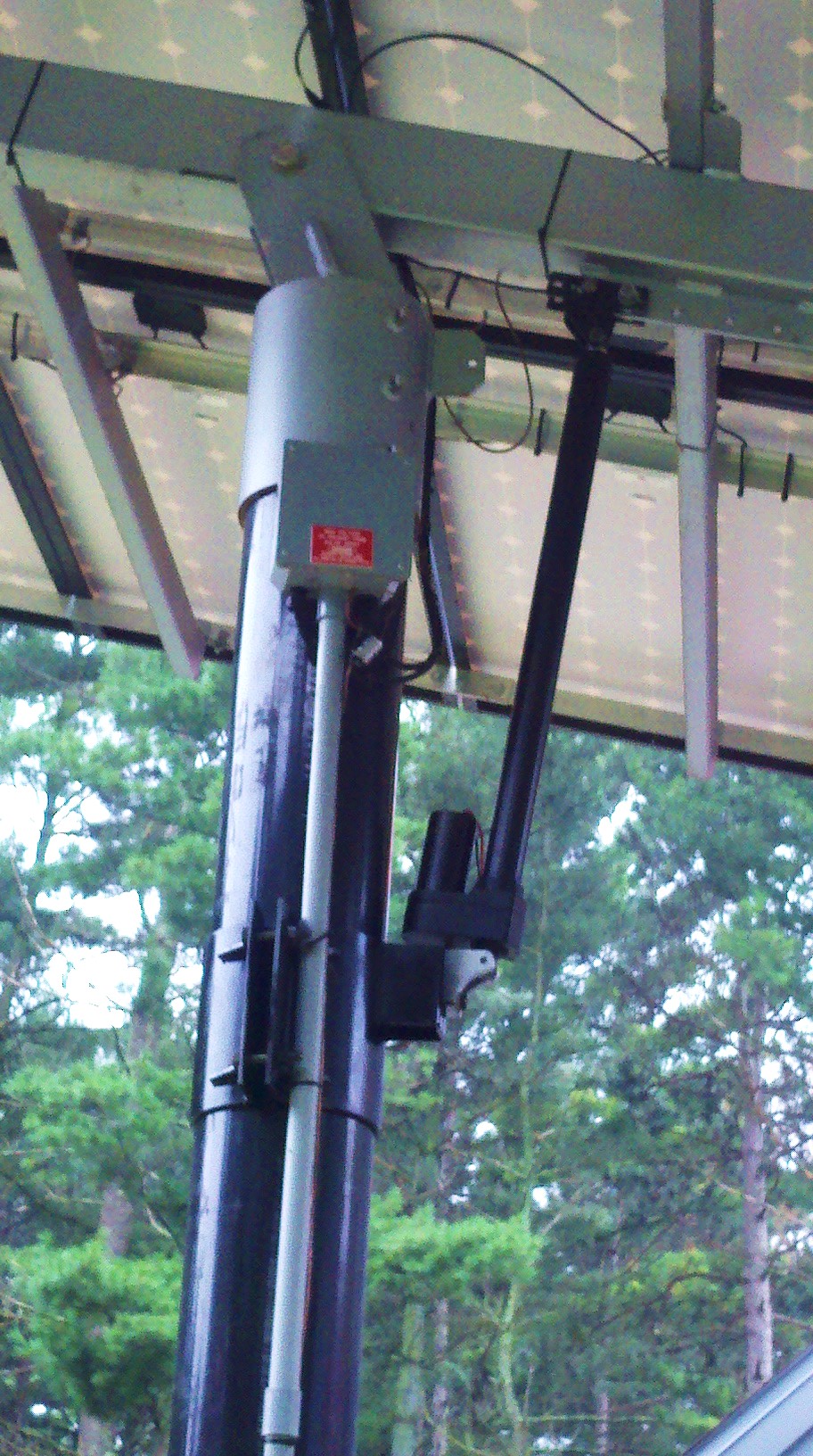
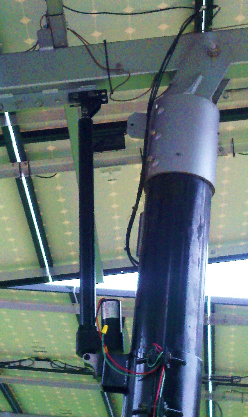
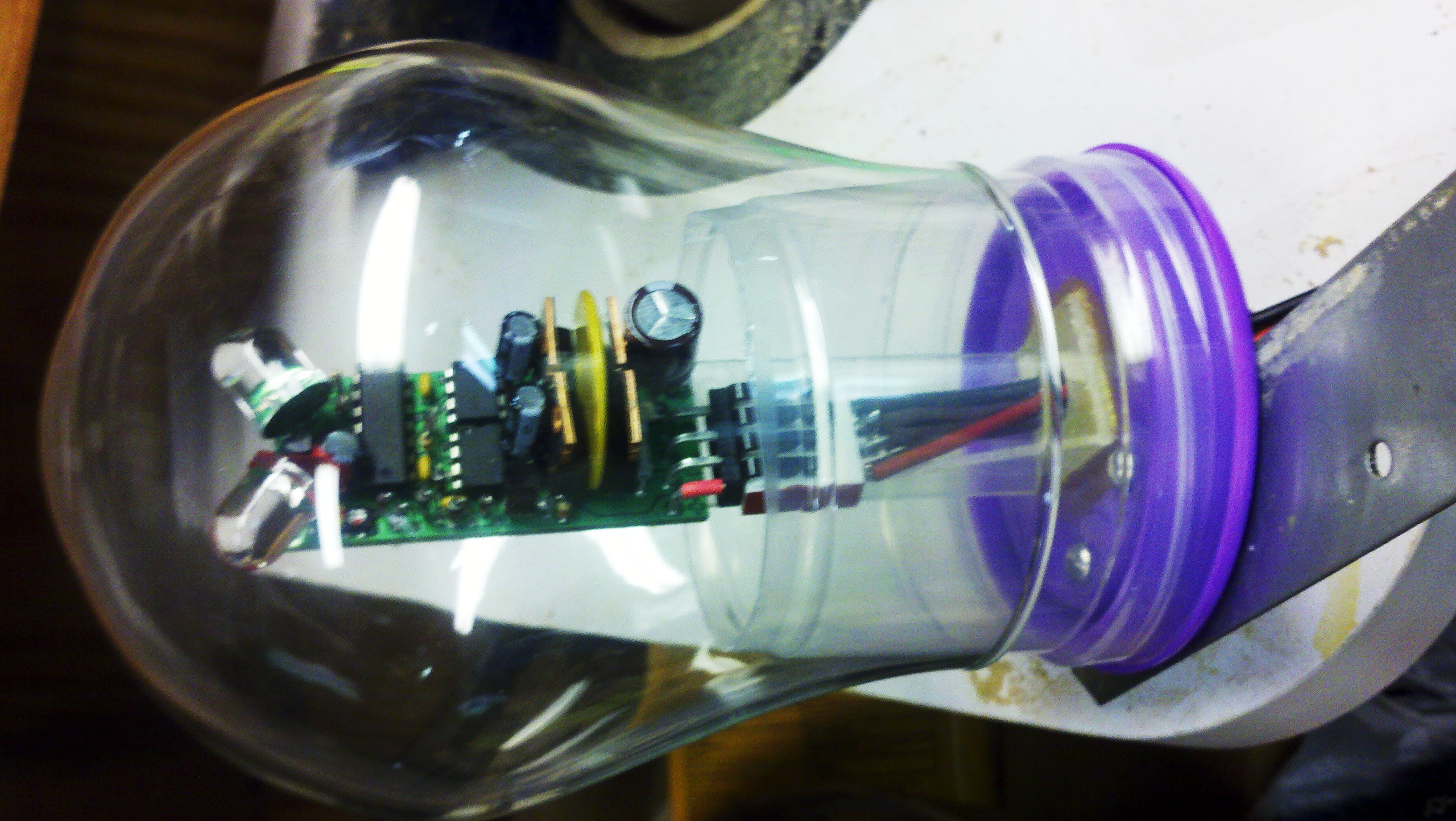
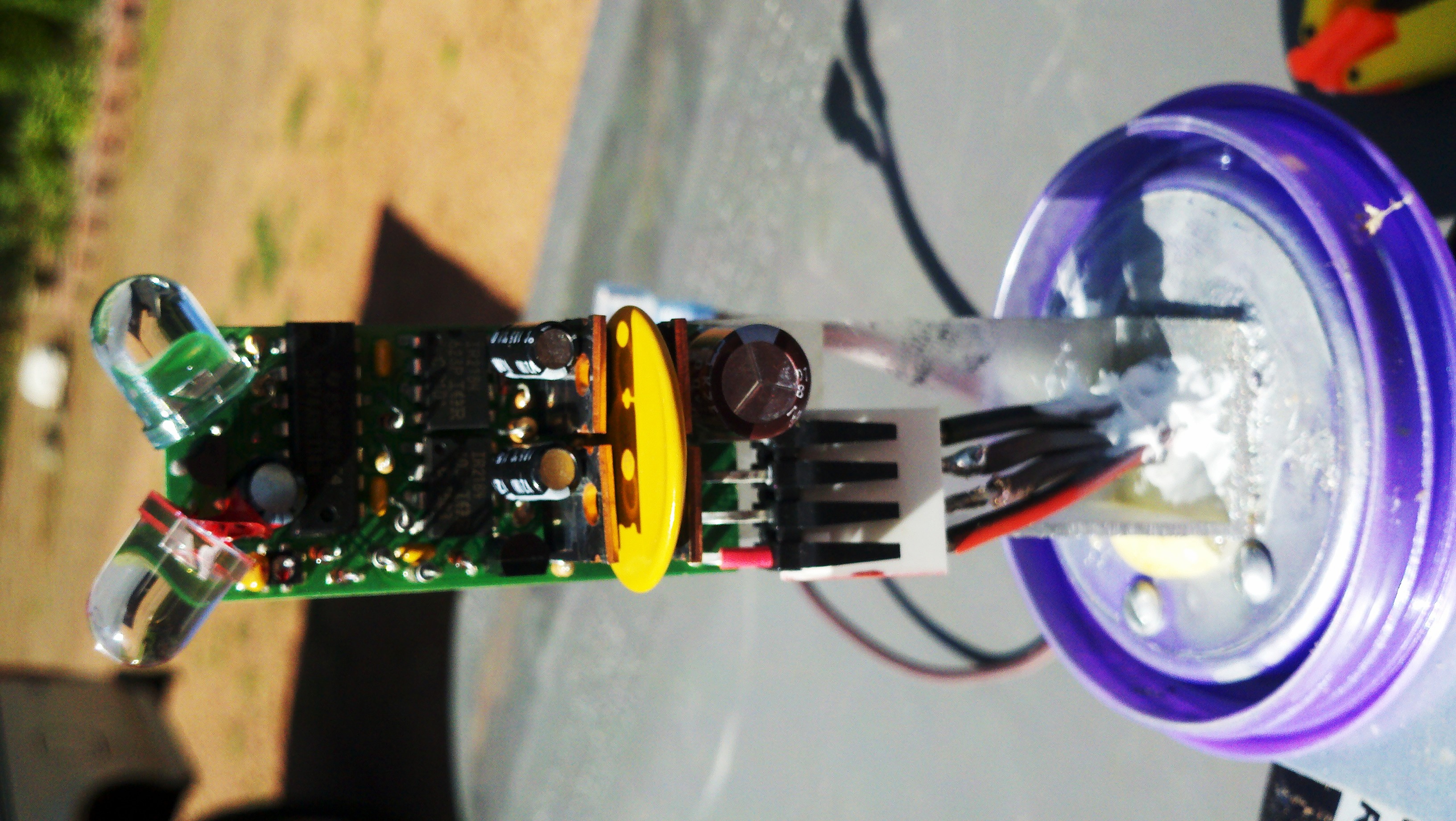
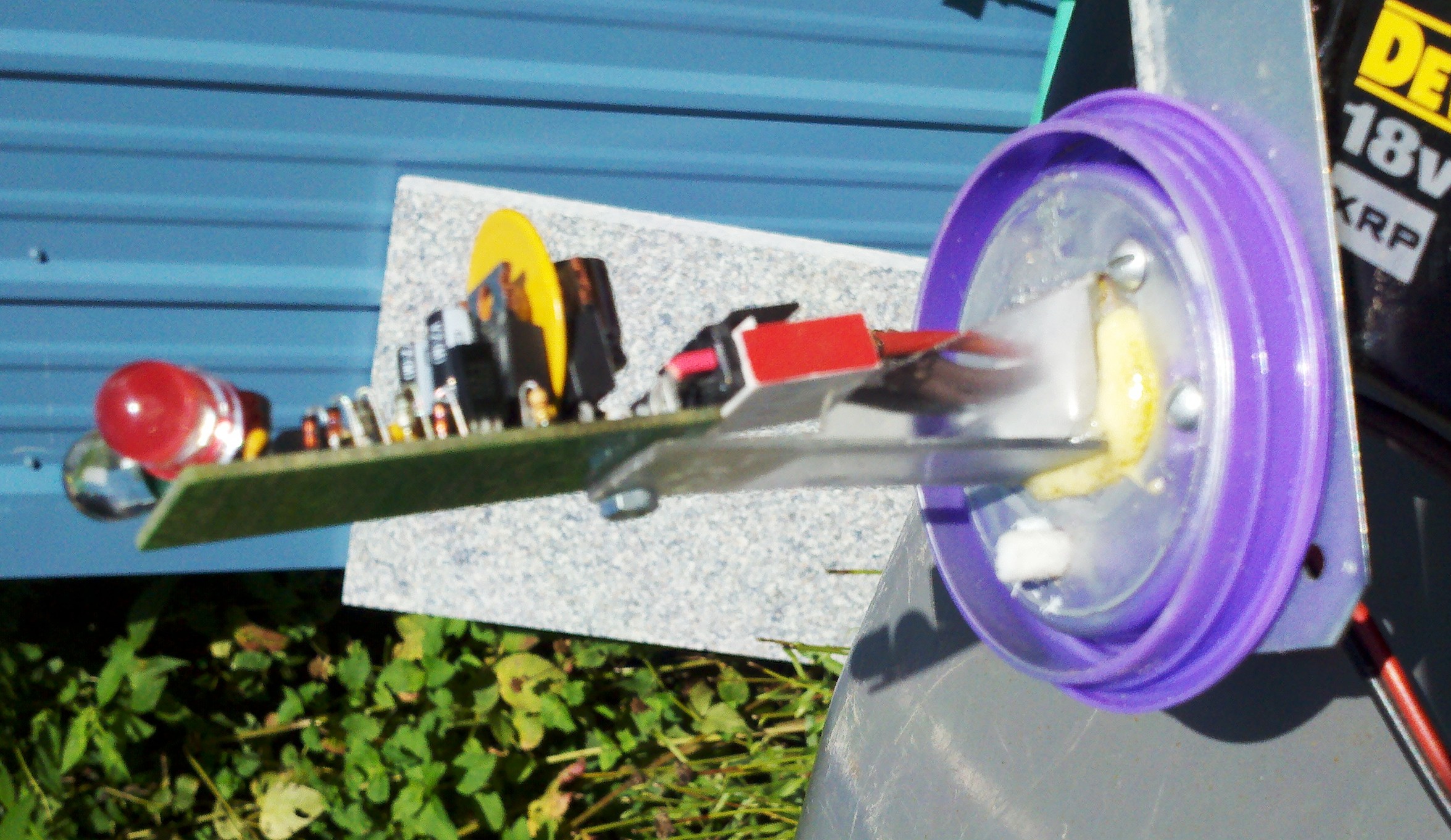
Ya, I said "Horizontal Axis" mount. Even though it is mounted on a pole
the main axis is horizontal oriented from East to West.
This is an unusual application with limited sun exposure. There is no East/West motion.
The PowerTech QARL-2436 (HV-36) linear actuator moves the panels in ALTitude only.
The motion is from nearly vertical in the South to flat at the zenith and somewhat over the top to the North.
Ok, this is not an ideal tracking motion but was the best for this location.
The glass is fairly thin and nearly wrinkle free.
If you look closely the base is from a clear plastic drinking cup
with a removable screw on lid and the cup bottom is cut off.
The tapered sides fits snugly into the glass dome and glued in place.
Note, the white nylon rope used as a wick type vent.
Bernd's Dual Axis Tracking pseudo polar axis Mount
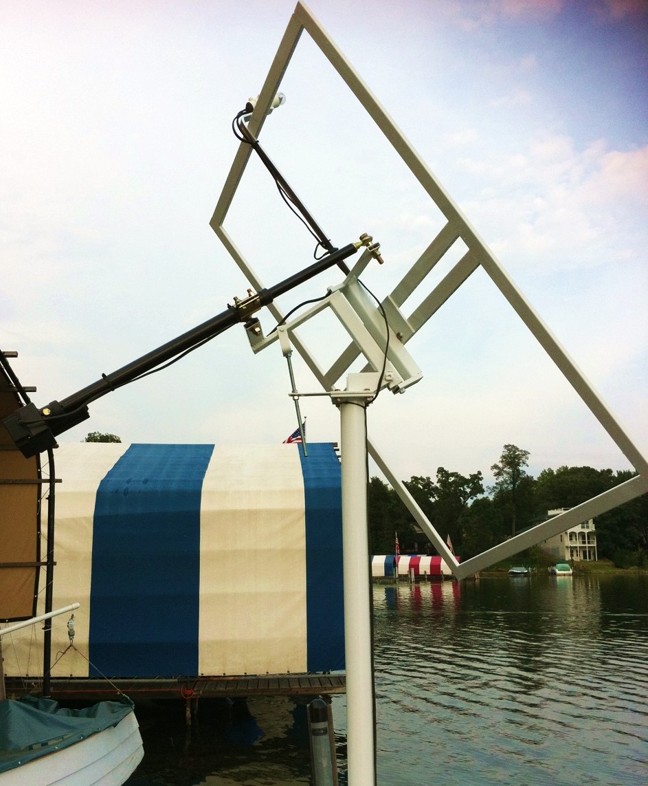
This is a nice design. The pseudo declination drive has not been added yet.
Denis Meunier's Dual Axis Tracking Vertical Axis Mounts
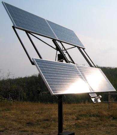
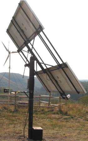
Denis Meunier builds single and dual axis tracking mounts commercially.
These are Vertical Axis designs.
He uses my LED3X series of trackers to control them.
He is in Canada. Please contact him for pricing.
<deny@mcsnet.ca>
Virgil Plunk's Dual Axis Tracking Mount
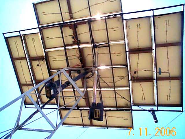
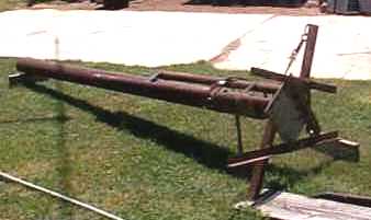
Virgil Plunk made a huge dual axis PV array.
<vlp2@sbcglobal.net>
Rich Kozlowski's Dual Pseudo Polar Axis Tracking Mount
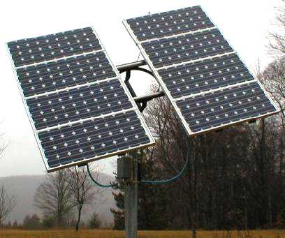
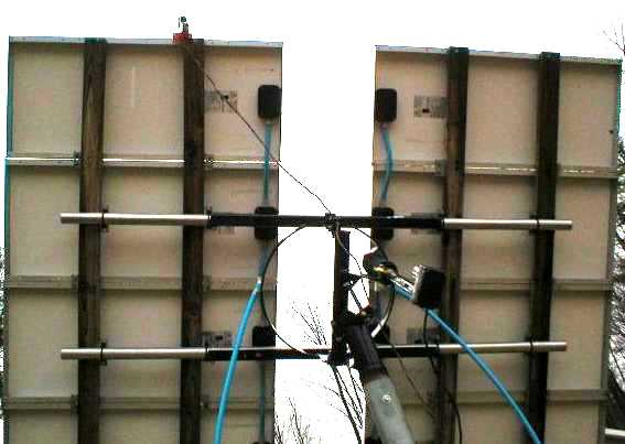
Rich is using an older LED3XS24Vc1 tracker.
He has a nice weather based web site.
http://www.rsklogic.com/weather
Jeff McIntyre's PV Pseudo Polar Axis Mount
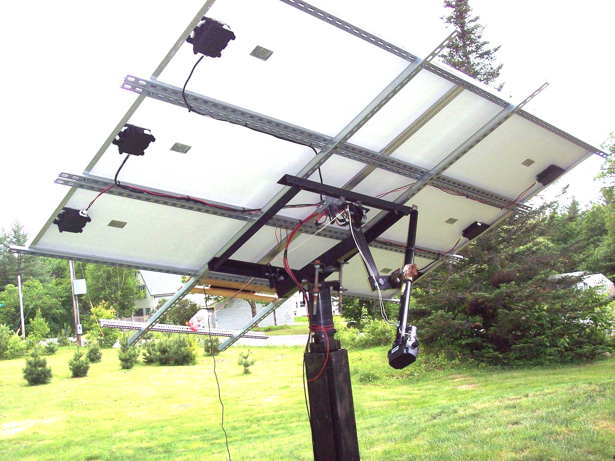
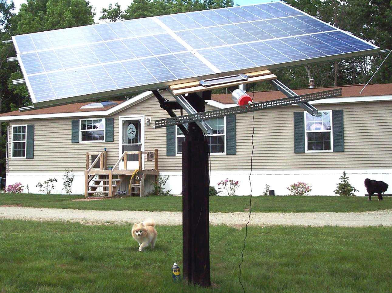
Jeff McIntyre built this very nice pseudo polar axis mount.
This uses a single axis LED3XS24Vc3P in the jar.
He lives in New Hampshire
DEClination is seasonally adjusted with the pair of large bolts.
Jeff has an extensive weather webpage.
Video of the last 24 hours of his tracking system.
<jeff@maccnh.com>
Duncan Bray's PV Pseudo Polar Axis Mount
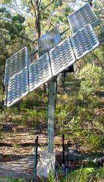
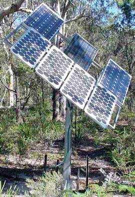
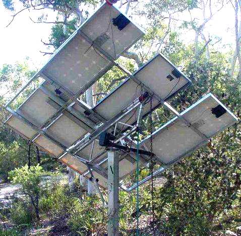
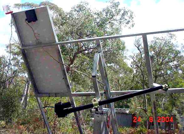
Duncan Bray built this very nice pseudo polar axis mount.
This uses a single axis LED3XS24Vc3P in the jar.
He lives in New South Wales, Australia.
David Rhodes's PV Pseudo Polar Axis Mount
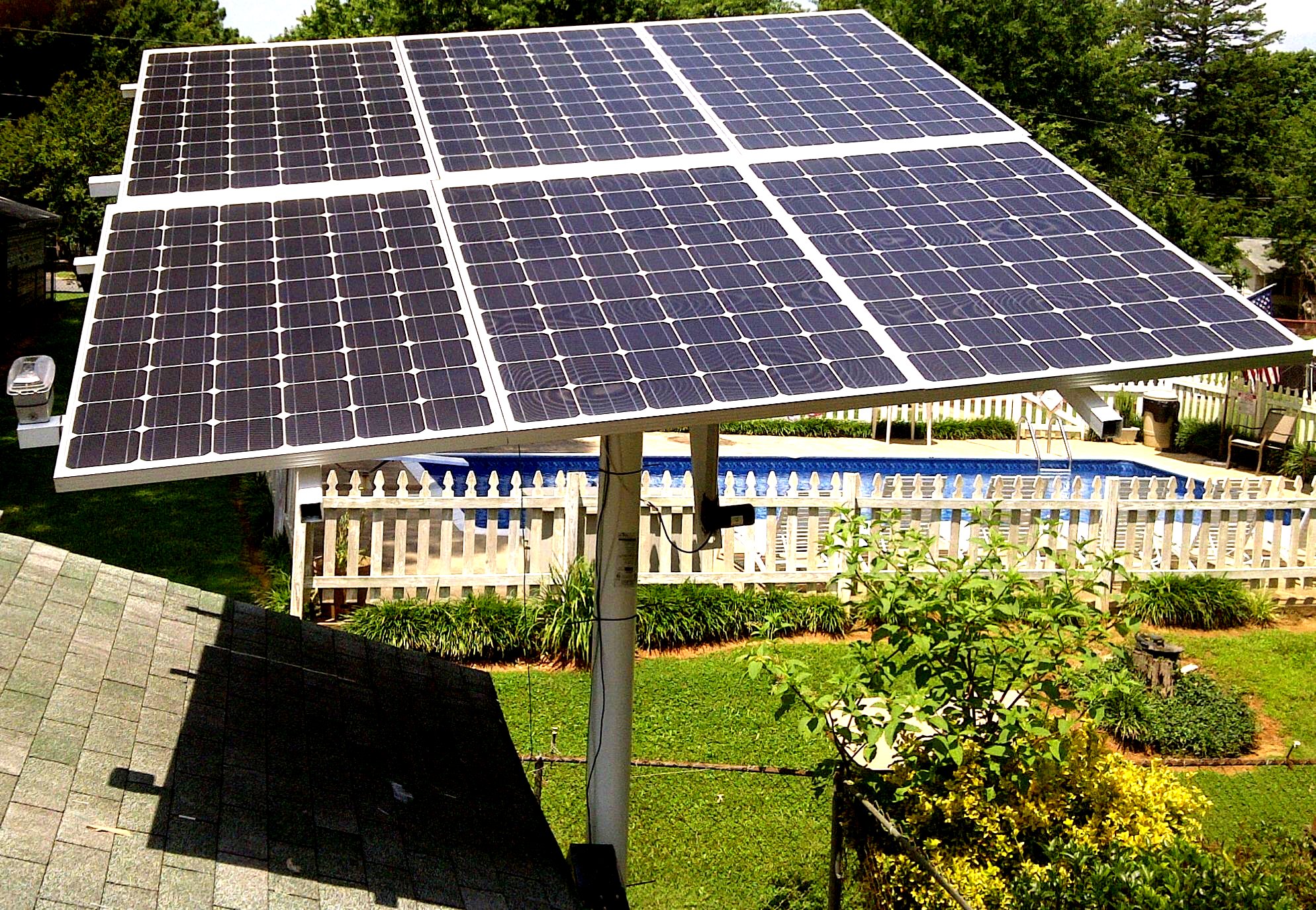
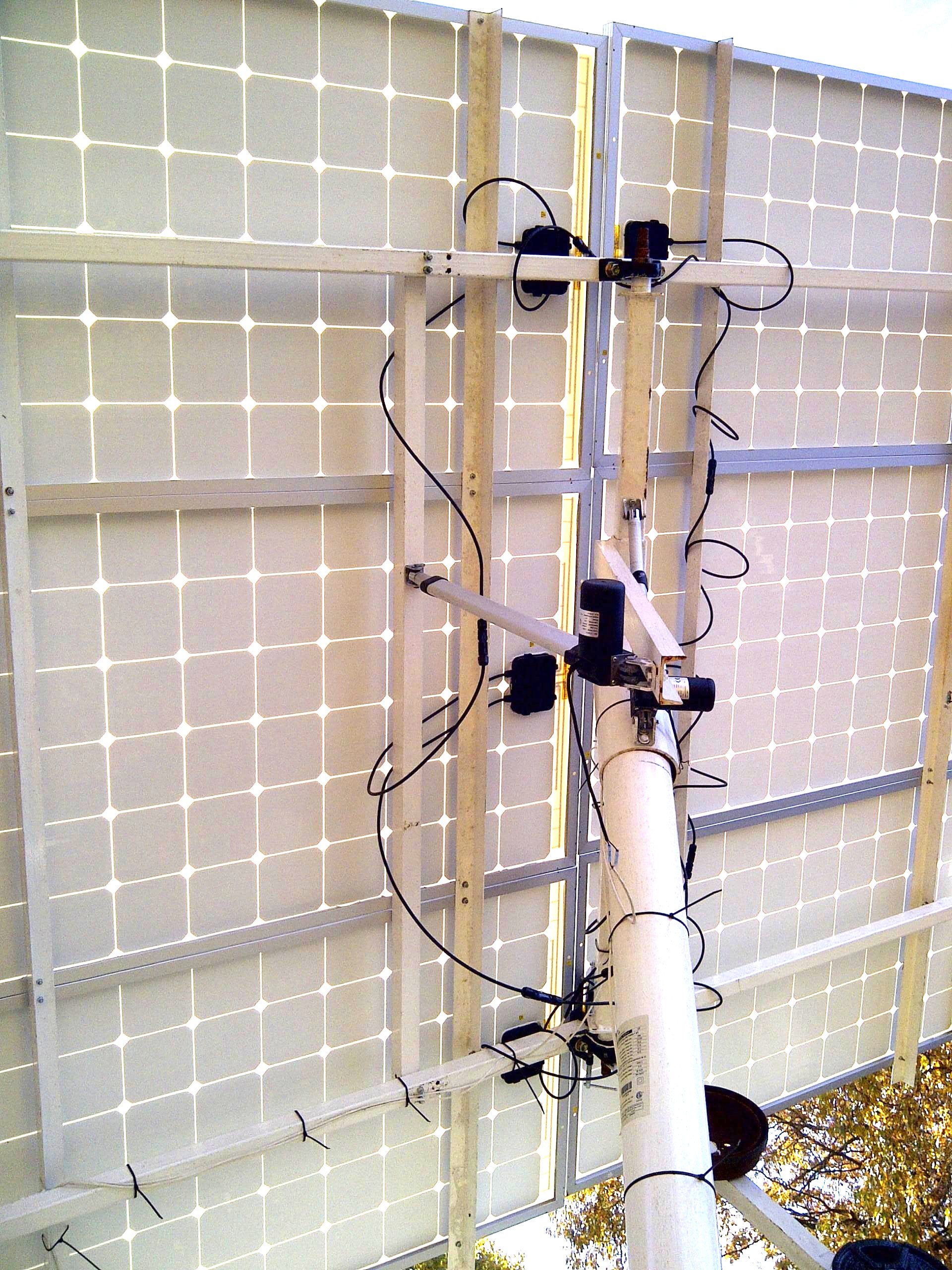
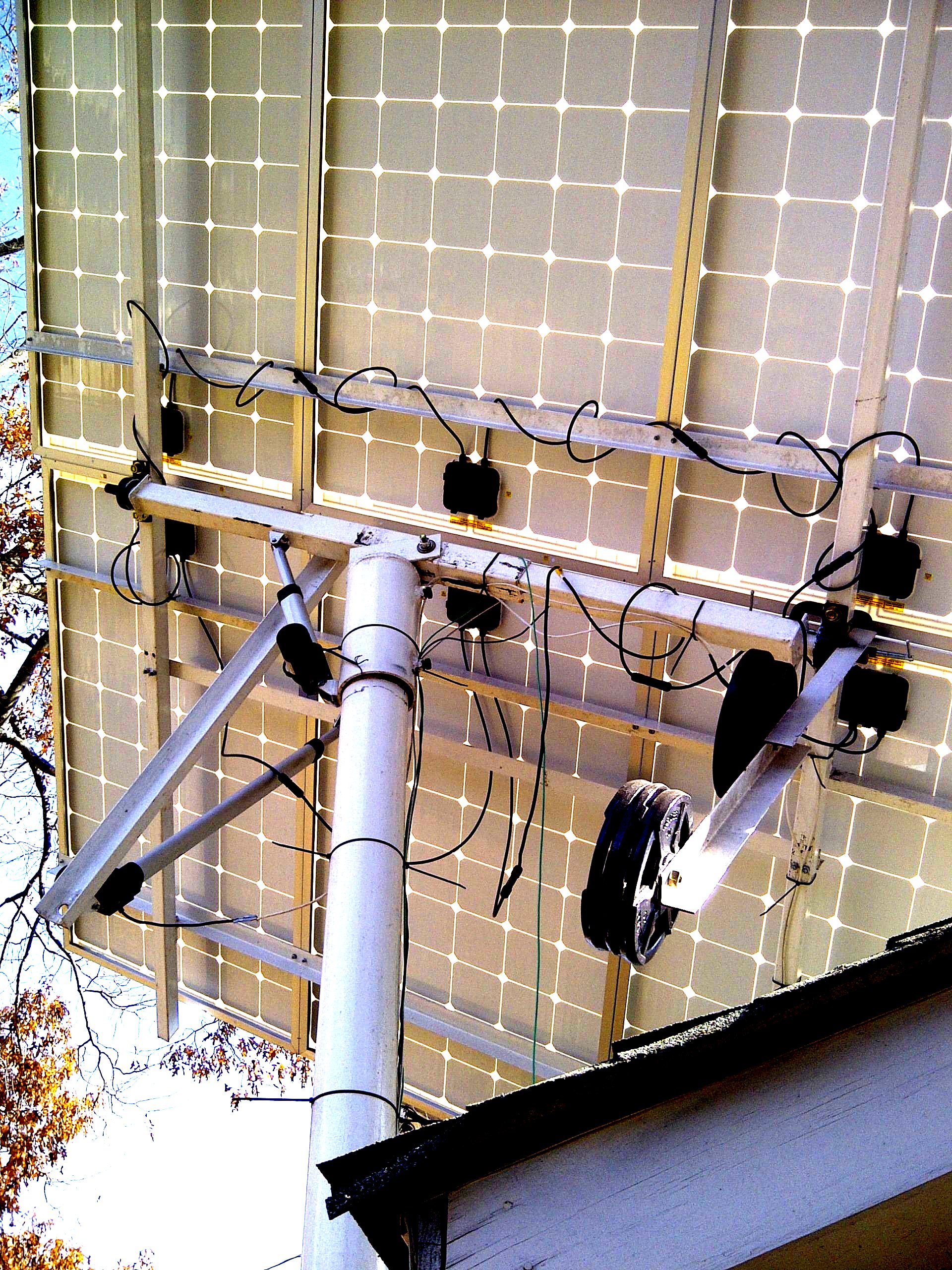
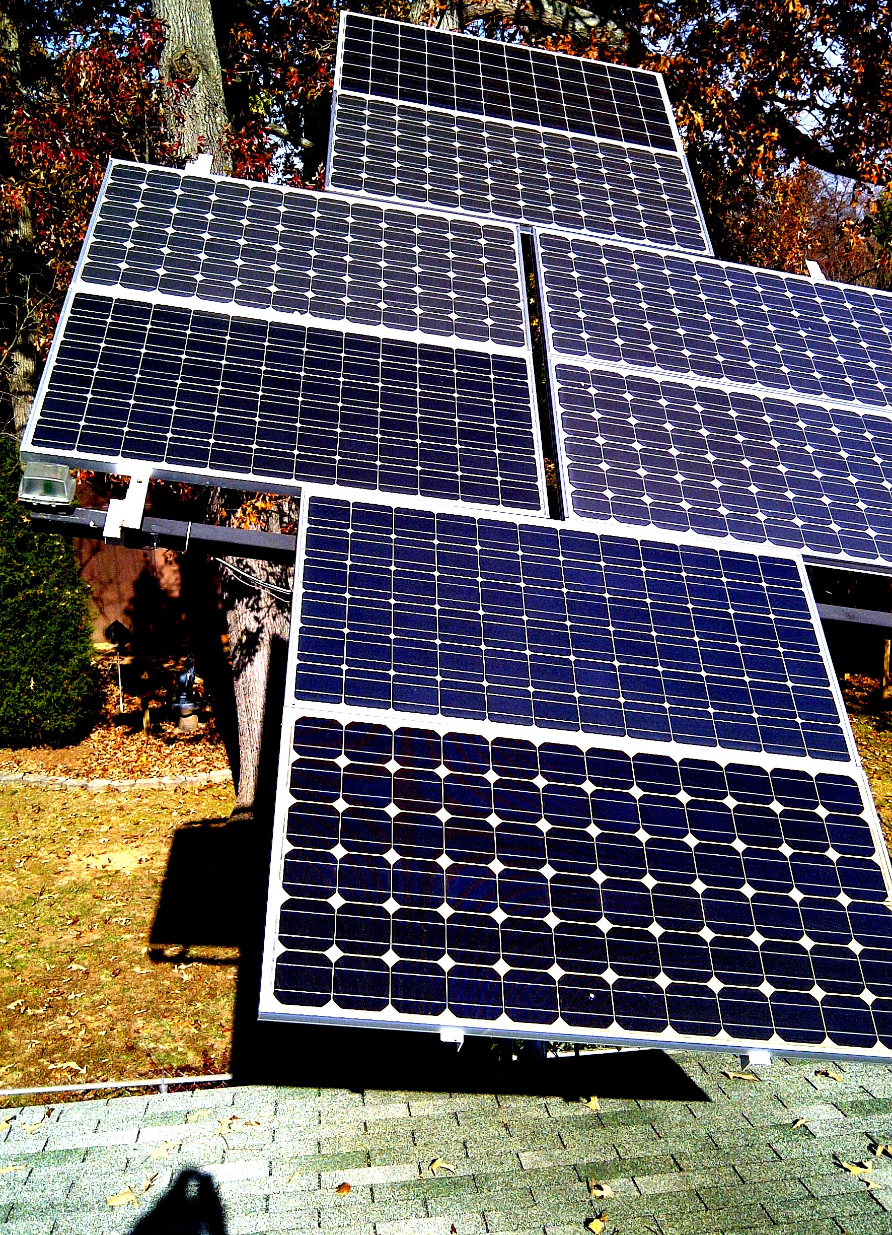
David built this very nice pseudo polar axis mount. In this case it's high up on a pipe. 6 Helios 250 watt panels. Movement is with large linear actuators.
Note the counter balance weights to balance things out. I highly recommend doing this.
The last picture is an older mount with 8 185 watt Sharp Panels.
luke
Joseph Luke's PV Polar Axis Tripod Mount
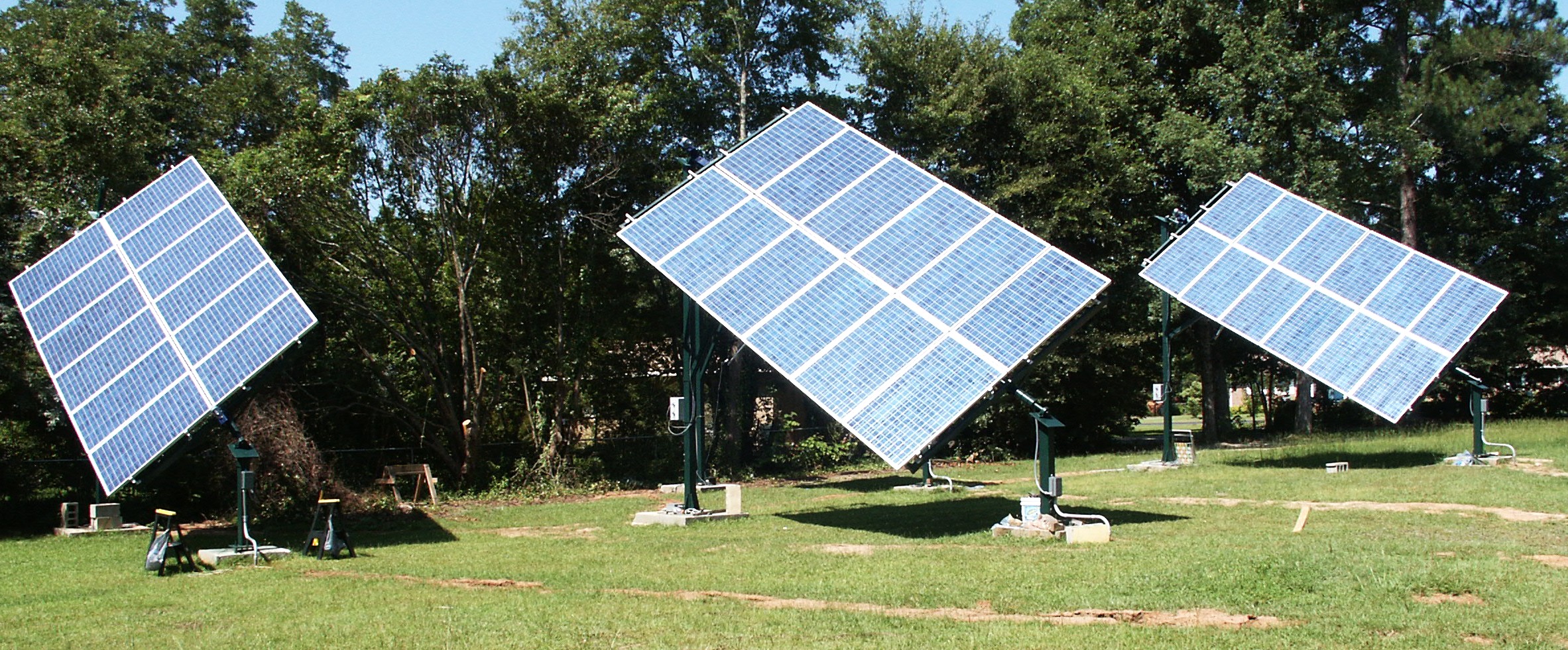
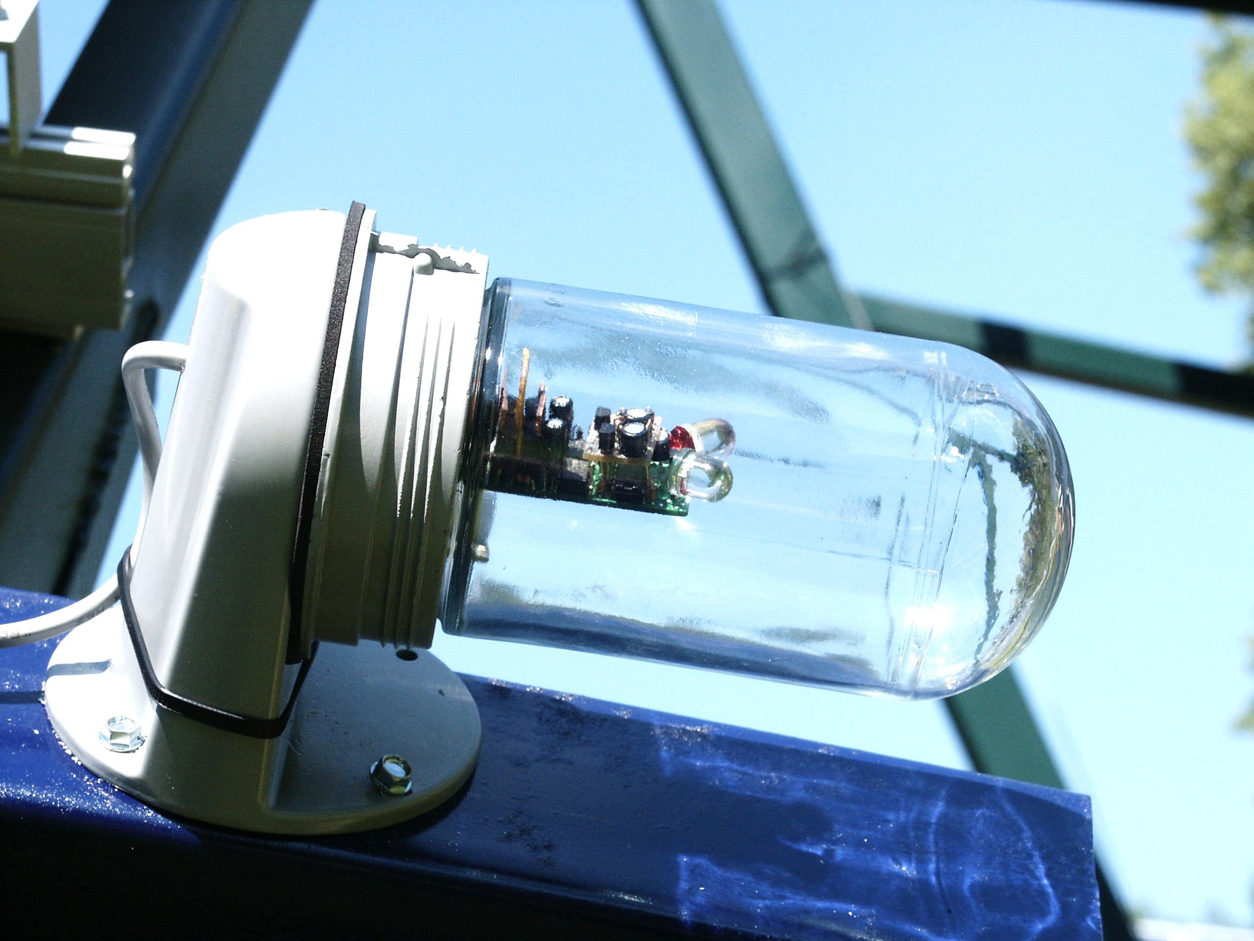
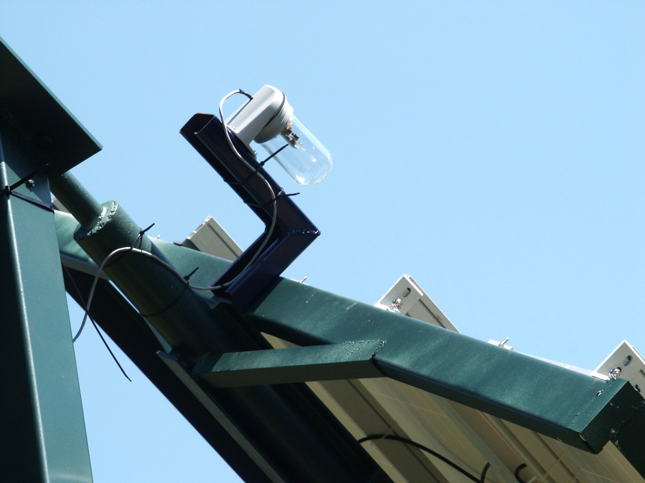
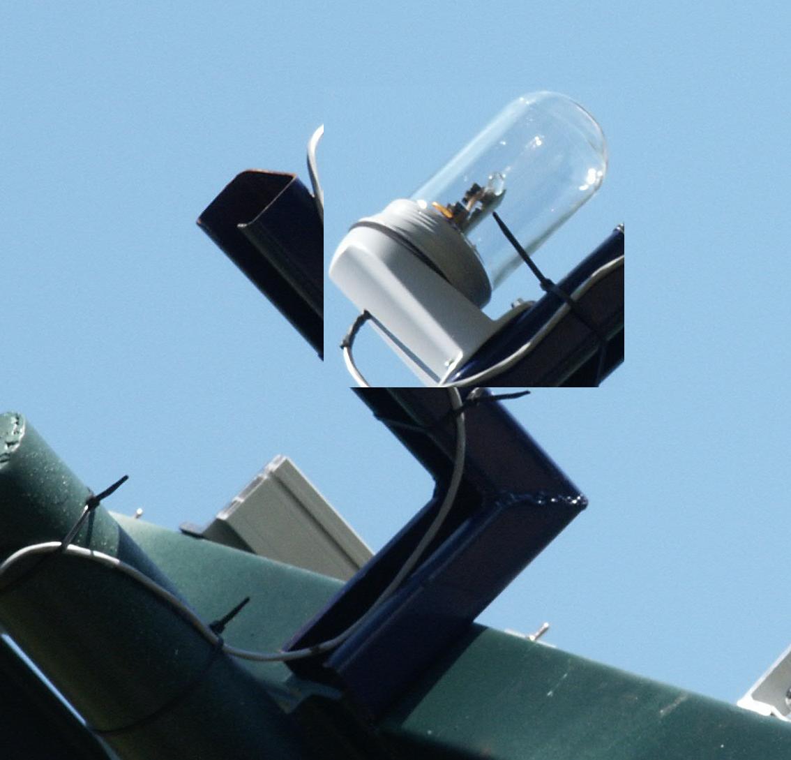
Joseph built this very nice tripod mount that uses a single axis tracker. The main leg is angled up from horizontal at the sites LATitude.
OK, not actually a tripod as the north end is a vertical pole but the concept is the same. The tracker used in this case is an LED3XS24Vc3RIP with the reverse inhibit feature.
Javier Aguirre's PV True Polar Axis Bipod Mount
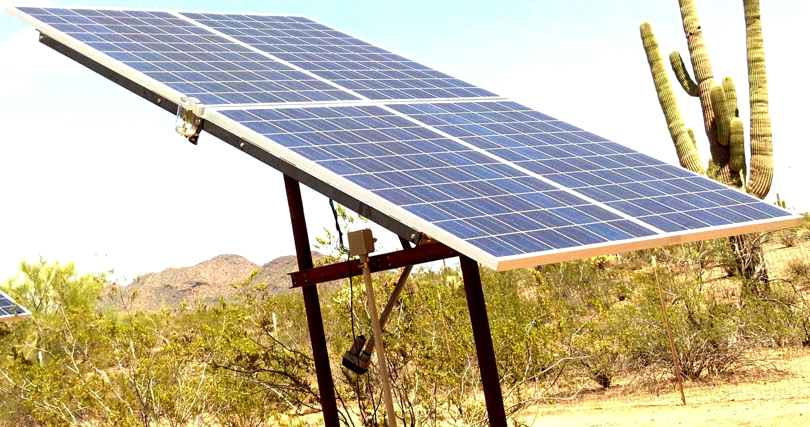
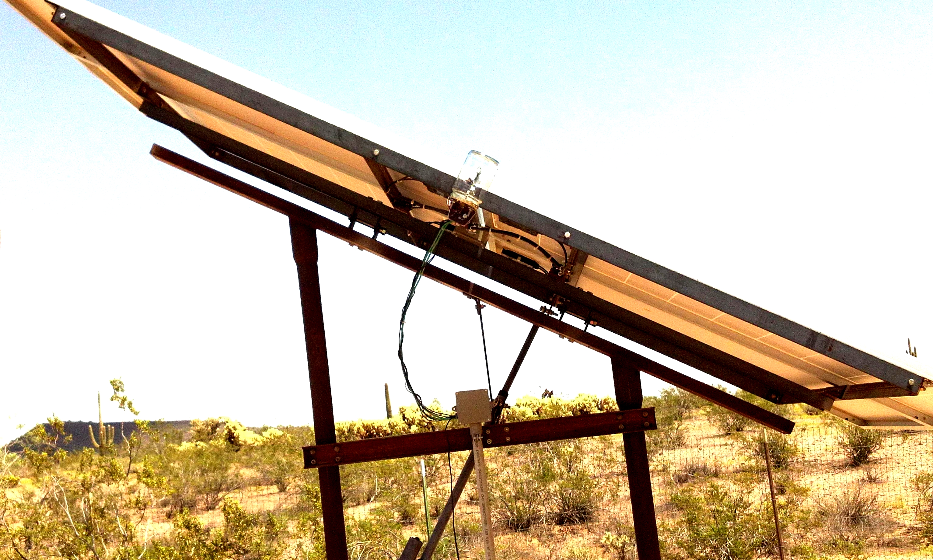
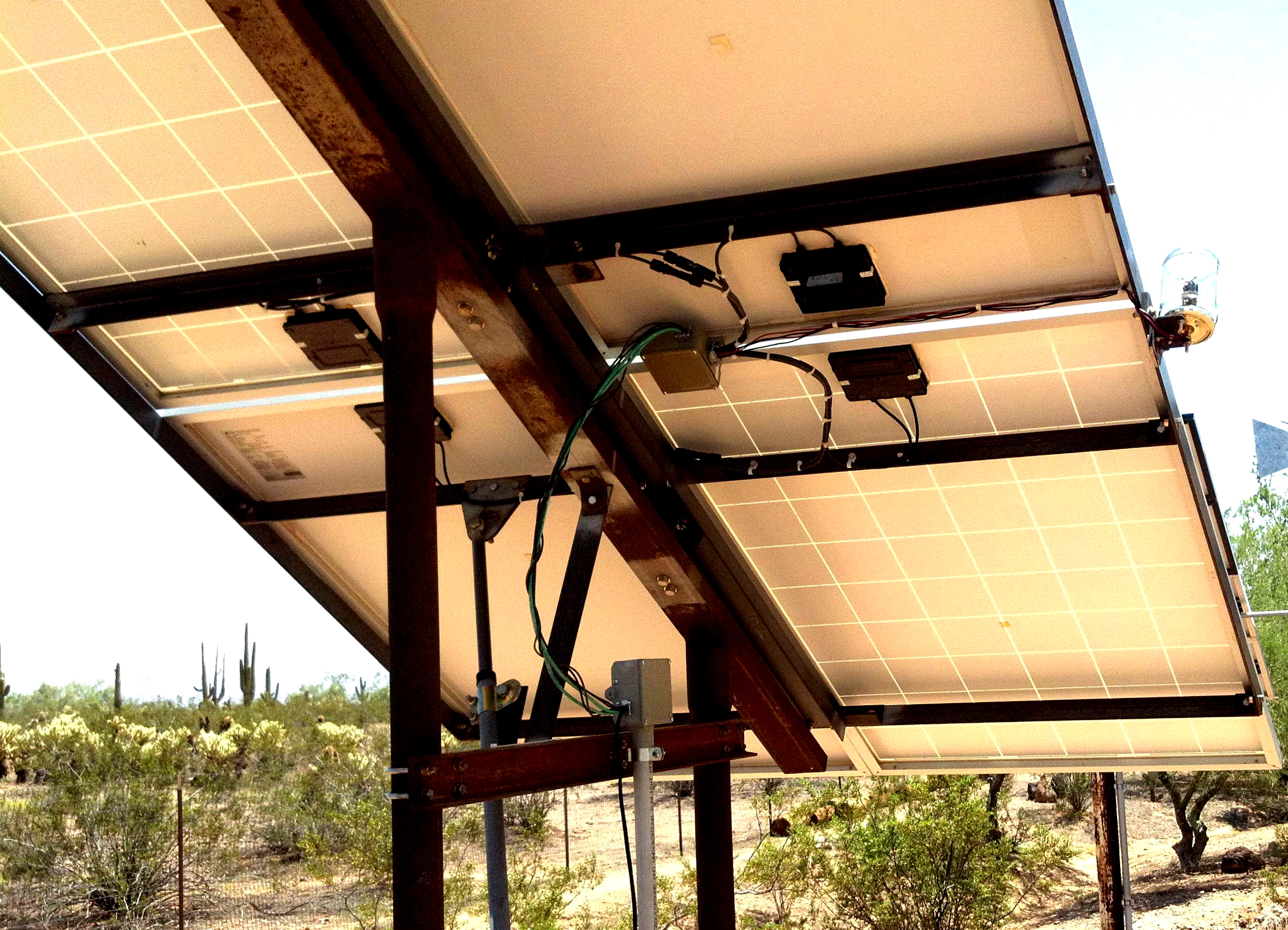
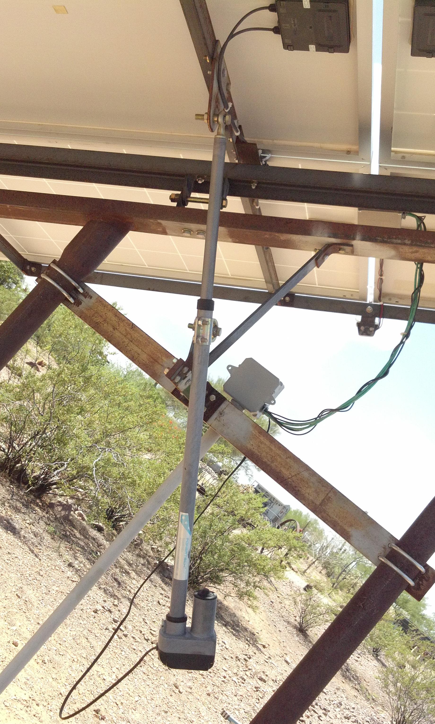
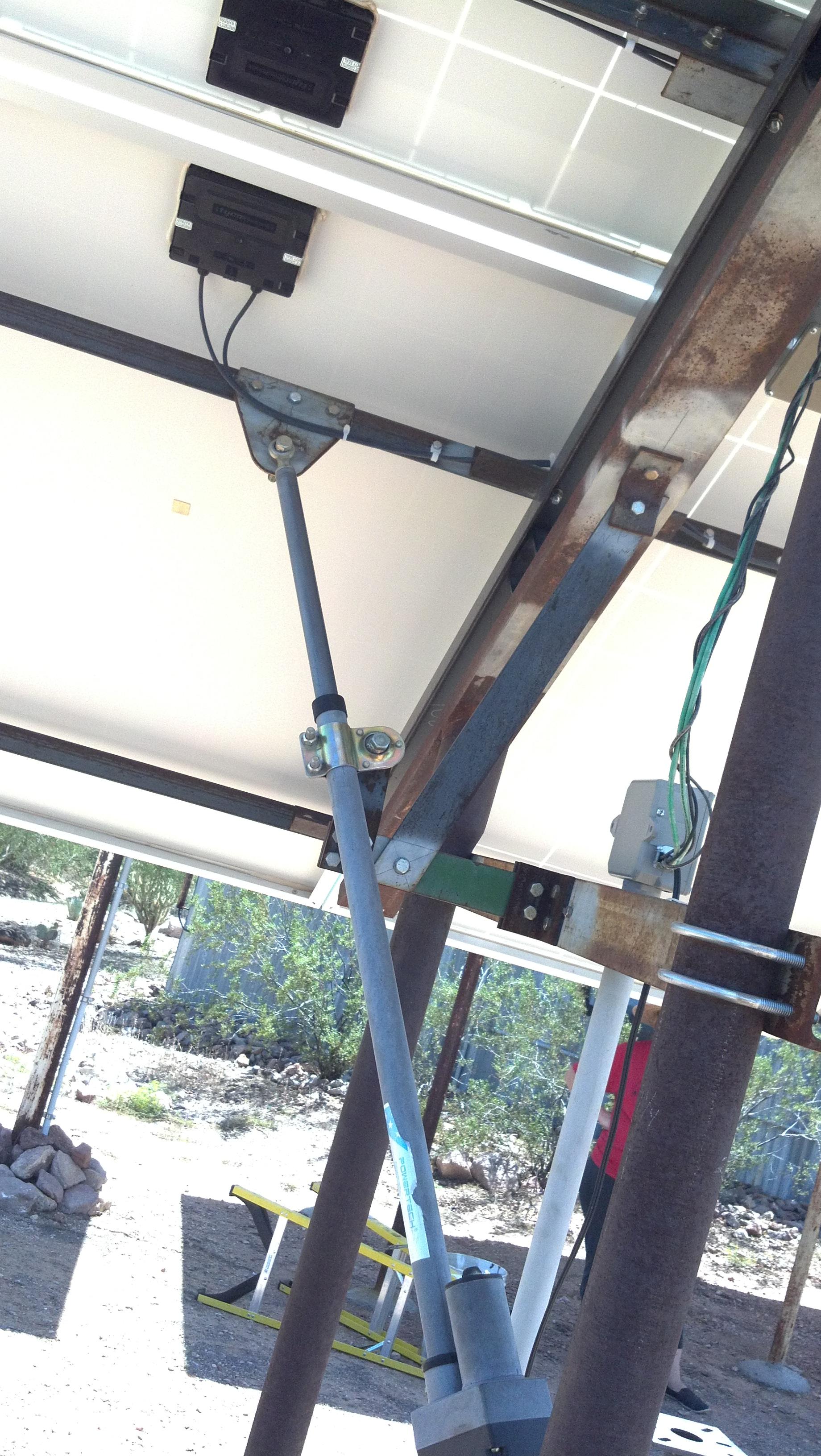
<Javier> built this very nice tripod mount that uses a single axis tracker. The main leg is angled up from horizontal, on the North, by the sites LATitude of about 34° in Arizona.
The vertical legs are made from very heavy drill stem.
OK, not actually a tripod as the north end is a vertical pole but the concept is the same. The tracker used in this case is an LED3XS24Vc3RIP with the Reverse Inhibit feature.
<Javier> said he would be willing to help if anyone had questions regarding construction of a similar system.
Dave Hill's Dual PV Polar Axis Tripod Mount
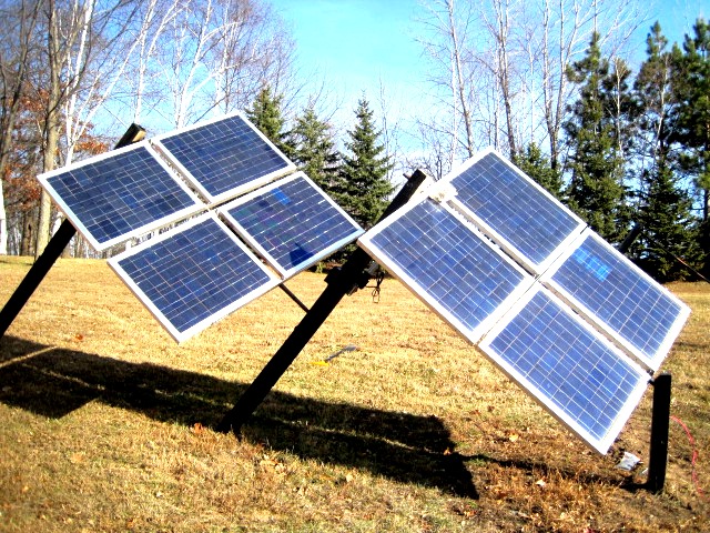
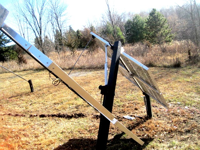
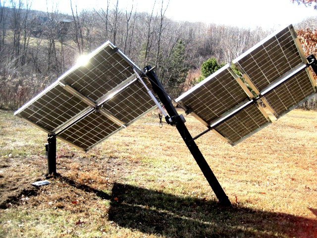
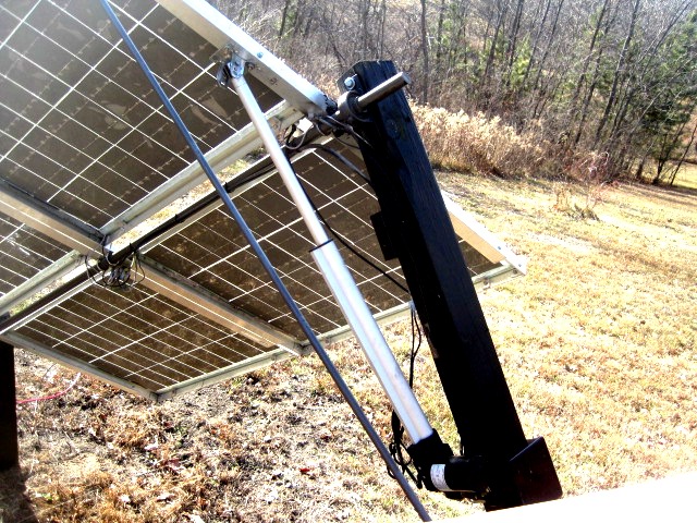
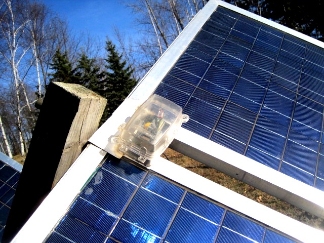
<Dave> built this very nice dual tripod mount that uses a single axis tracker with a second mount linked to the first. It looks to me more could be linked together, The main leg is angled up from horizontal at the sites LATitude.
OK, another one one leg short of a tripod. The tracker used in this case is an LED3XS24Vc3P in a nice domed plastic electrical box.
Energy Options PV Polar Axis Tripod Mount
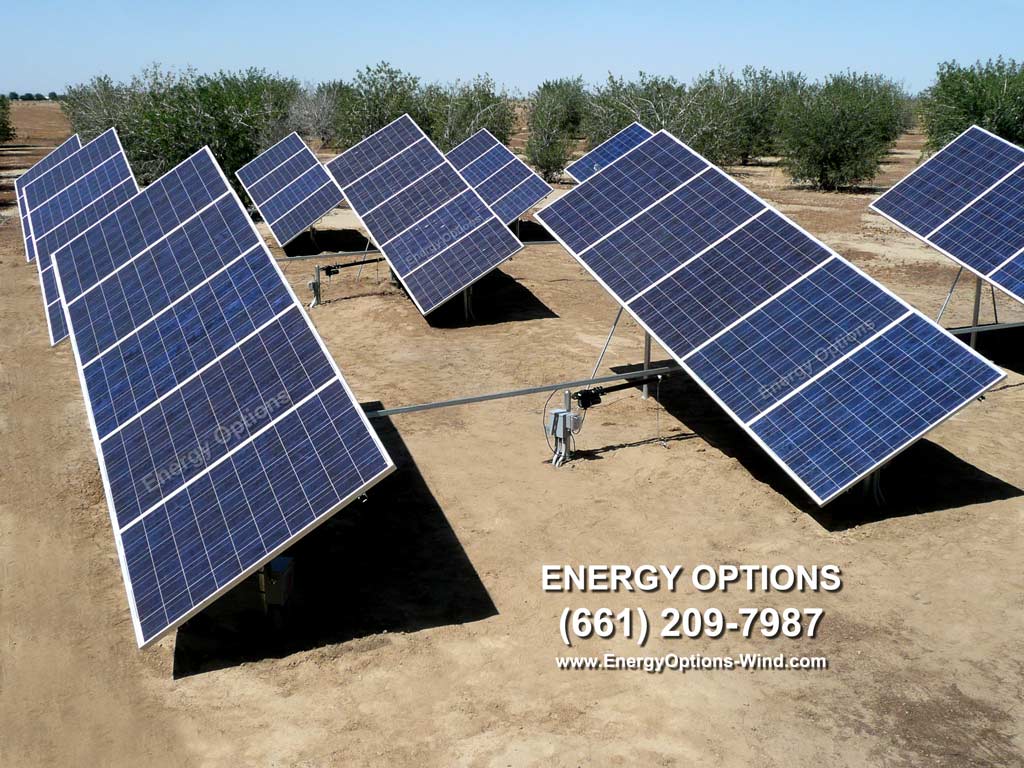
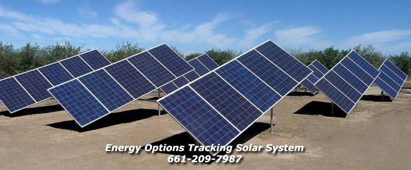
Energy Options has this very nice tripod mount for sale that uses a single axis tracker. The main leg is angled up from horizontal at the sites LATitude.
OK, not actually a tripod as the north end is a vertical pole but the concept is the same. The tracker used in this case is an LED3XS24Vc3RIP with the reverse inhibit feature.
This example has a link between several mounts with a linear actuator moving the set. Very cool!
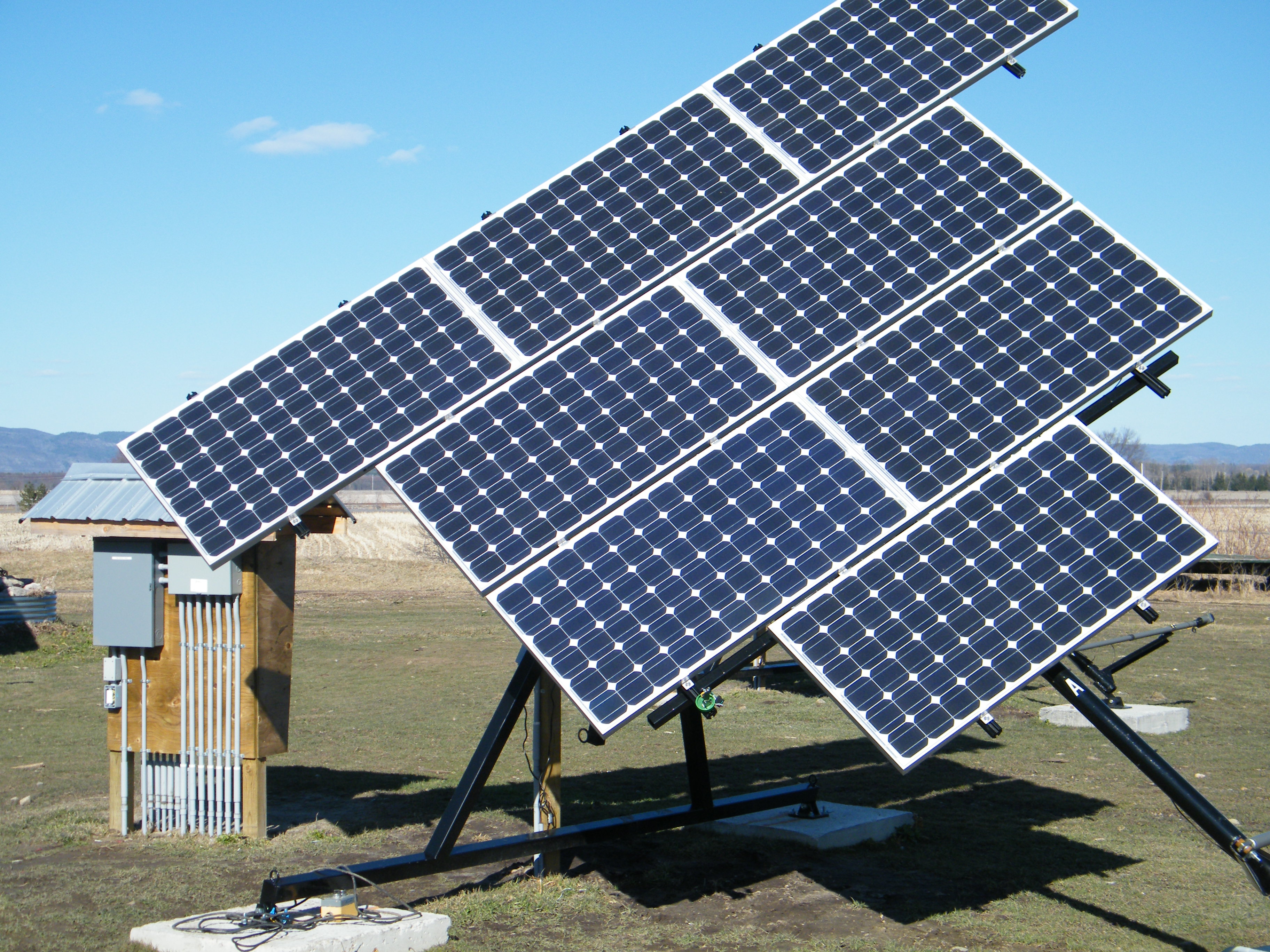
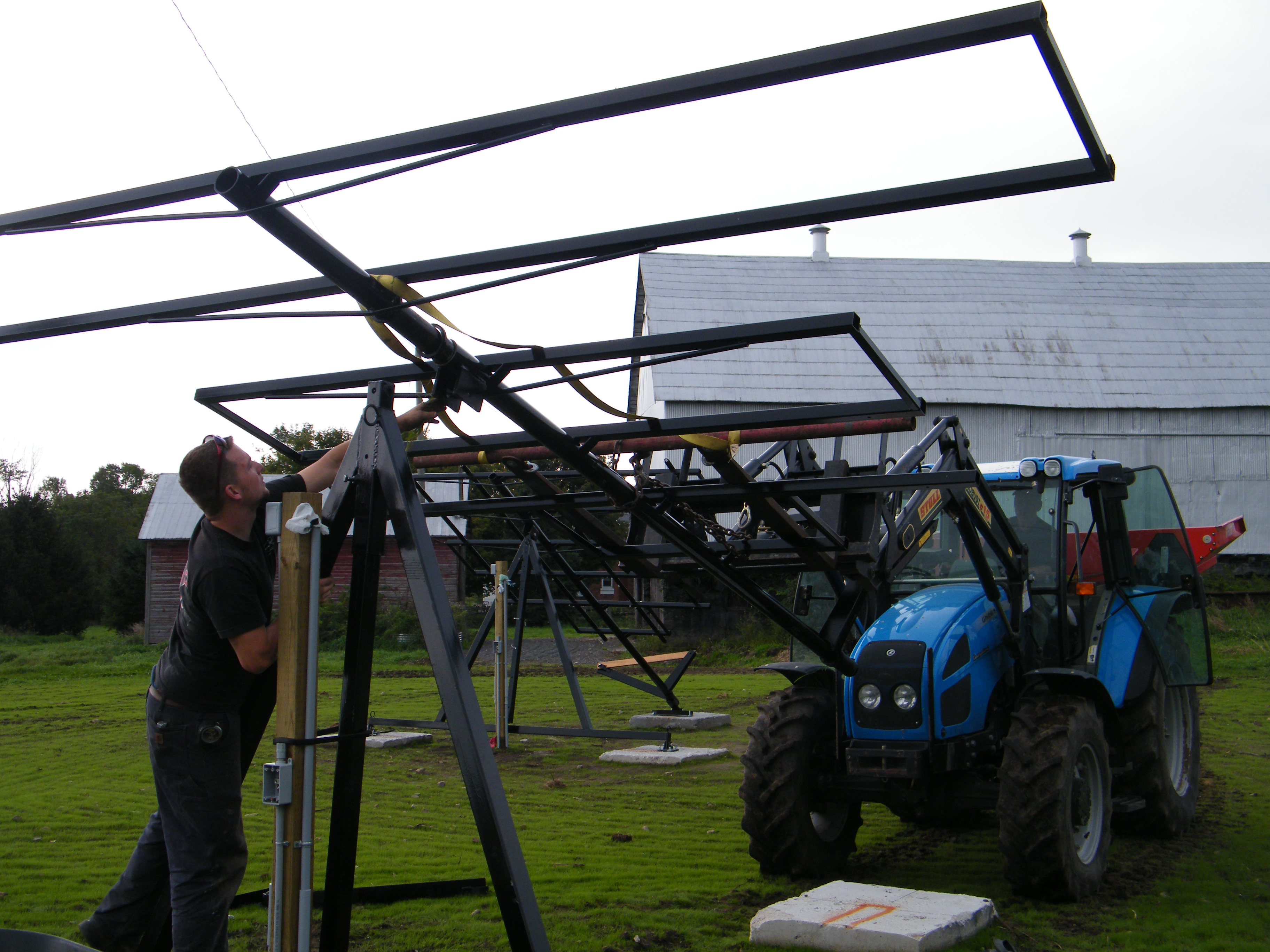
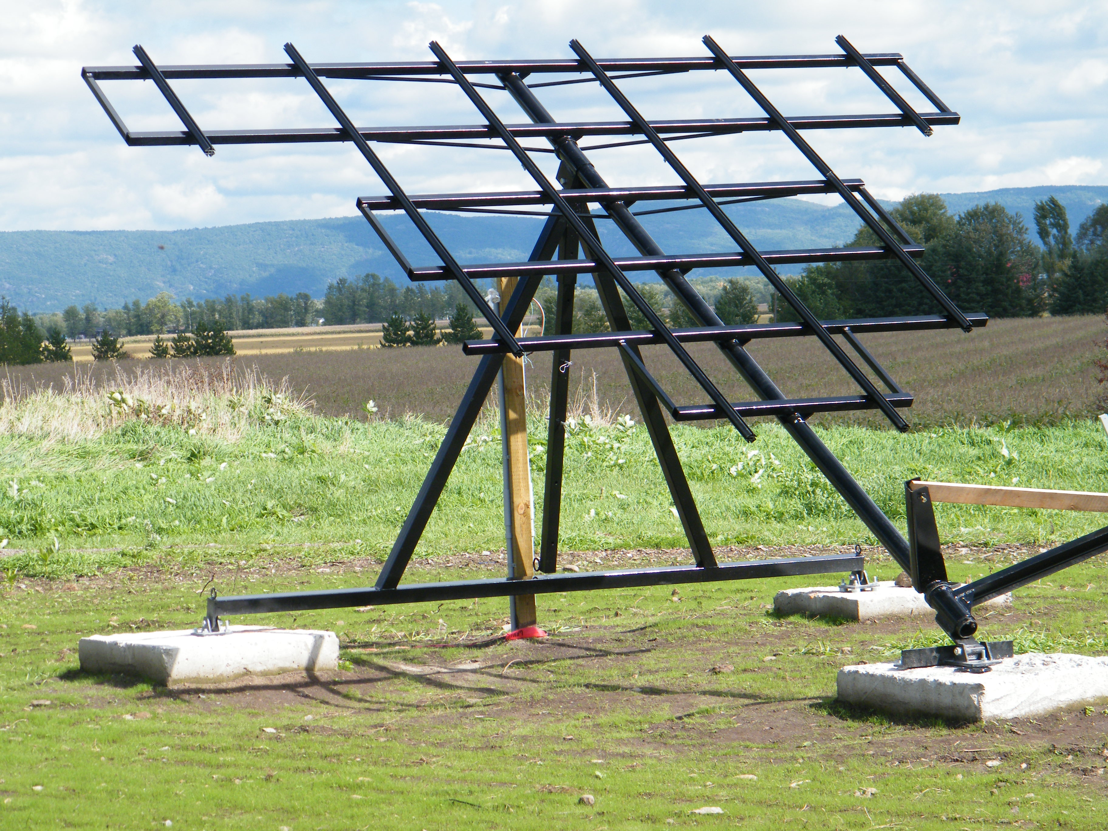
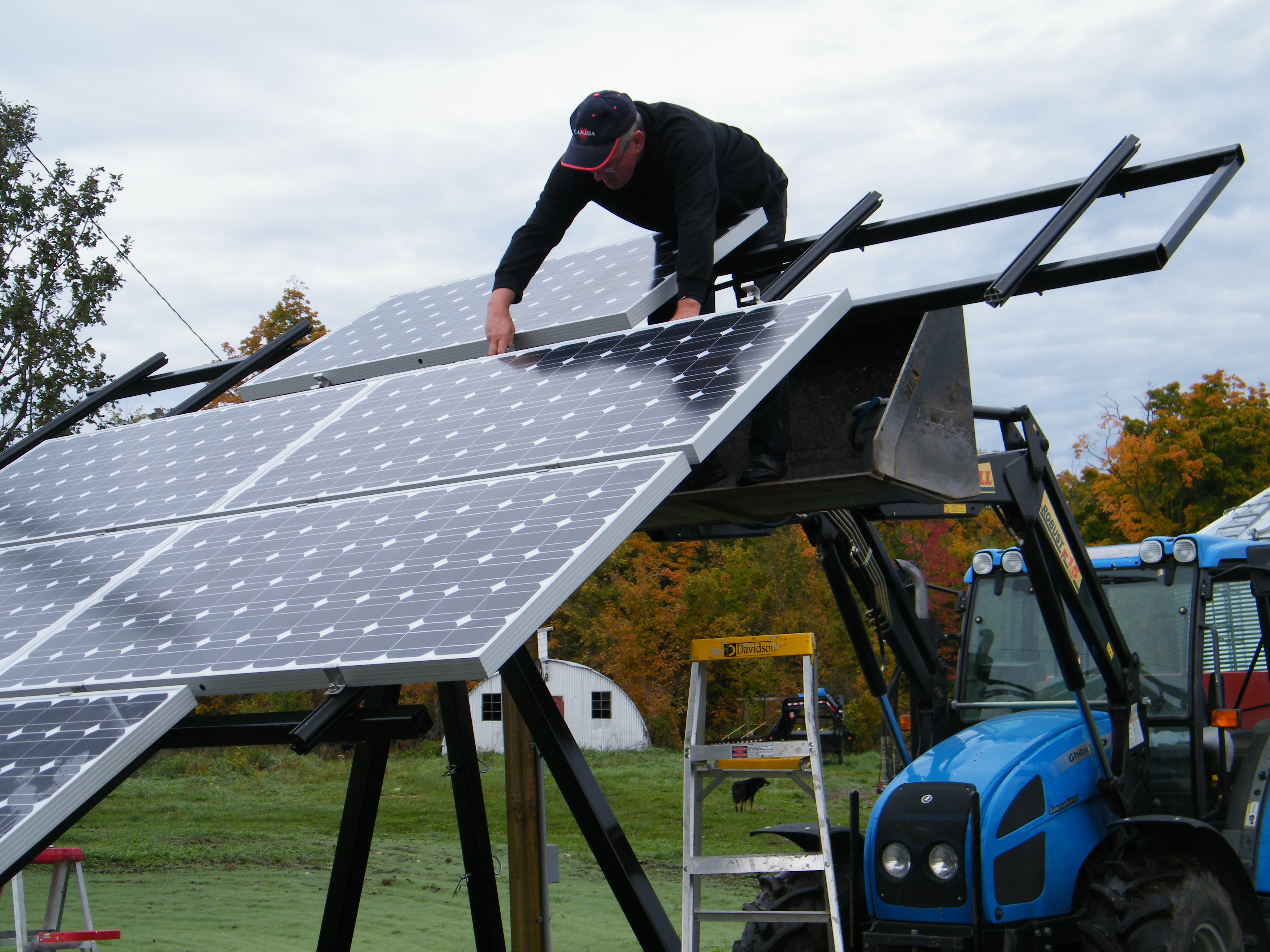
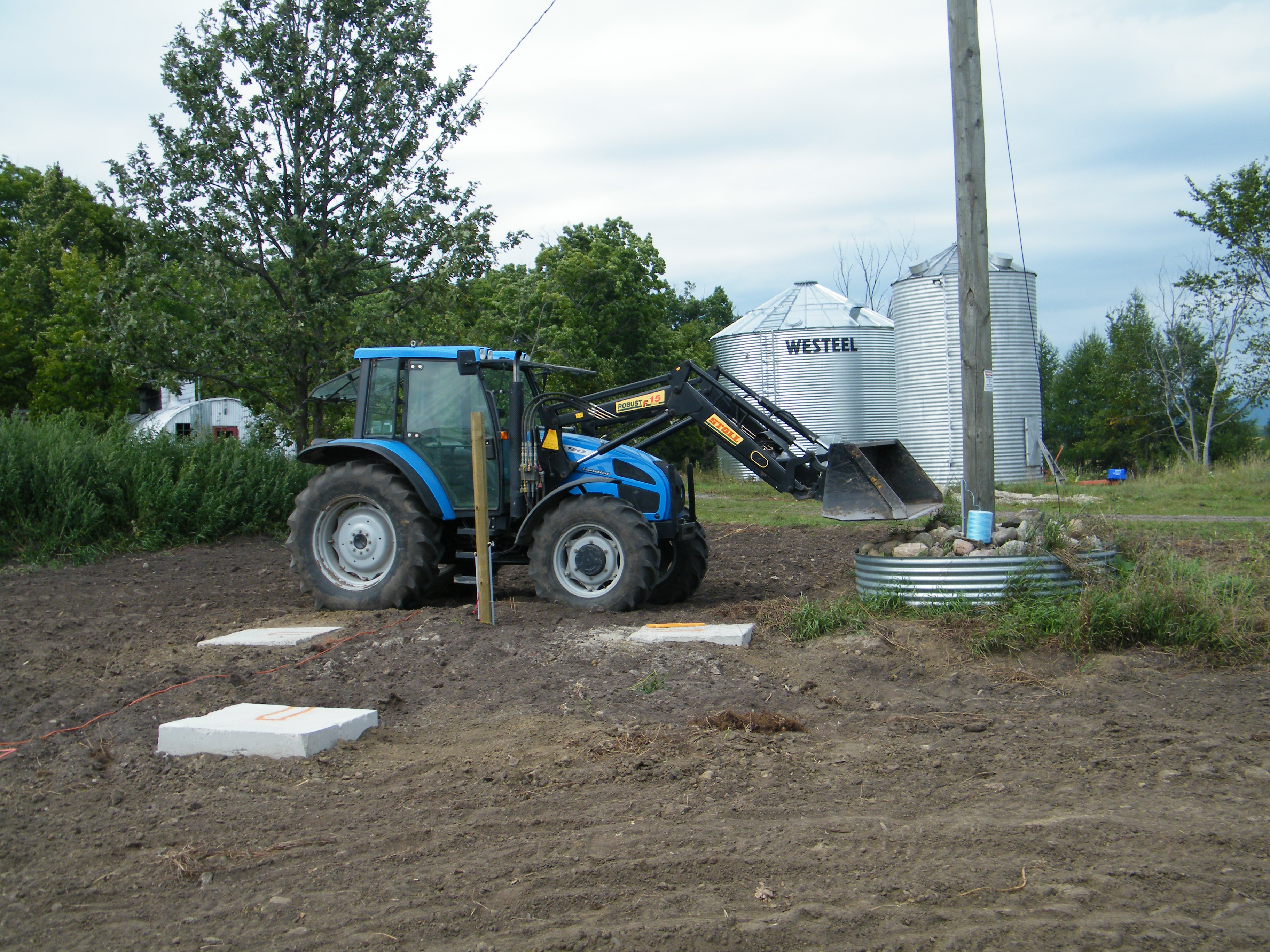
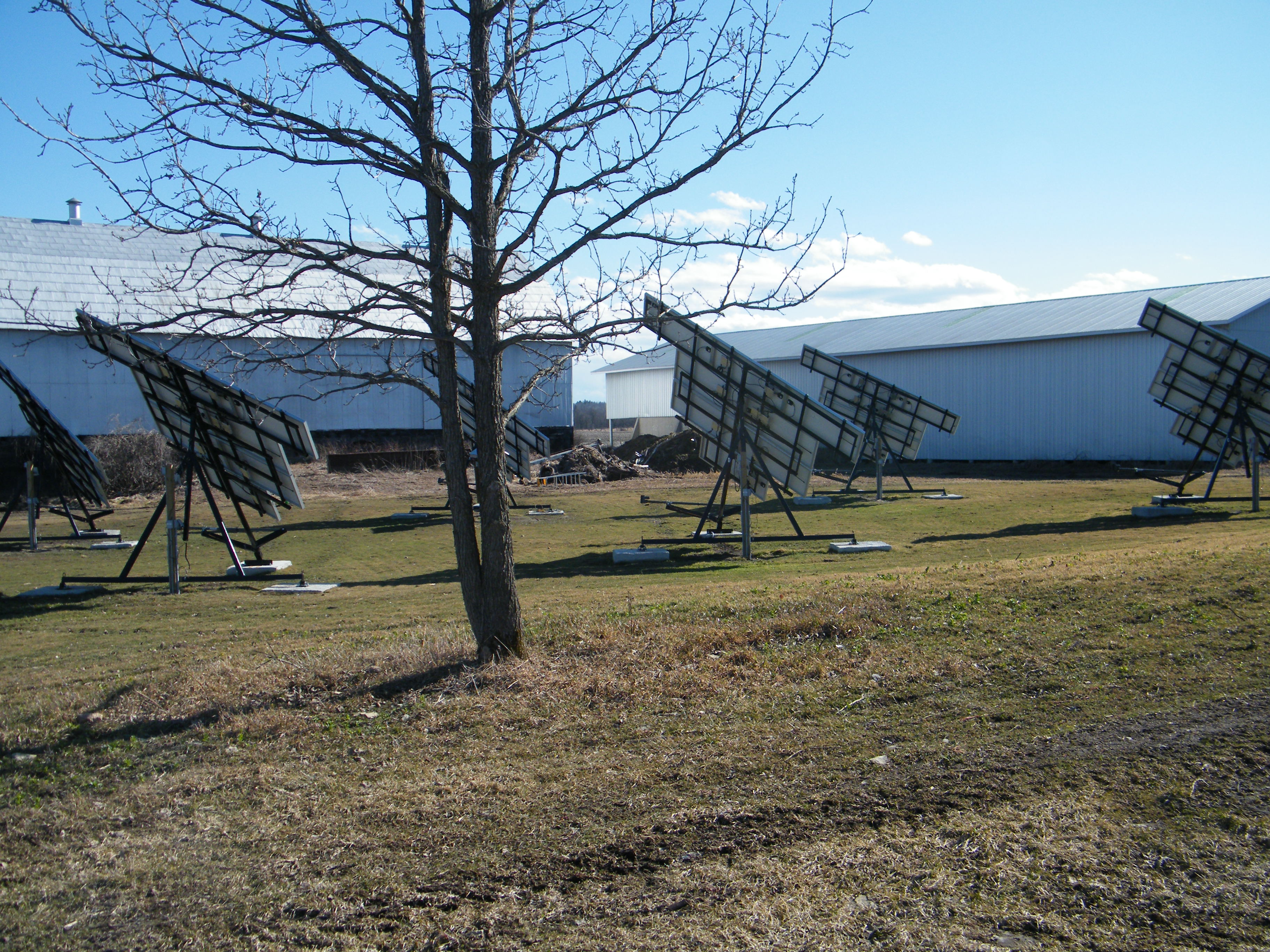
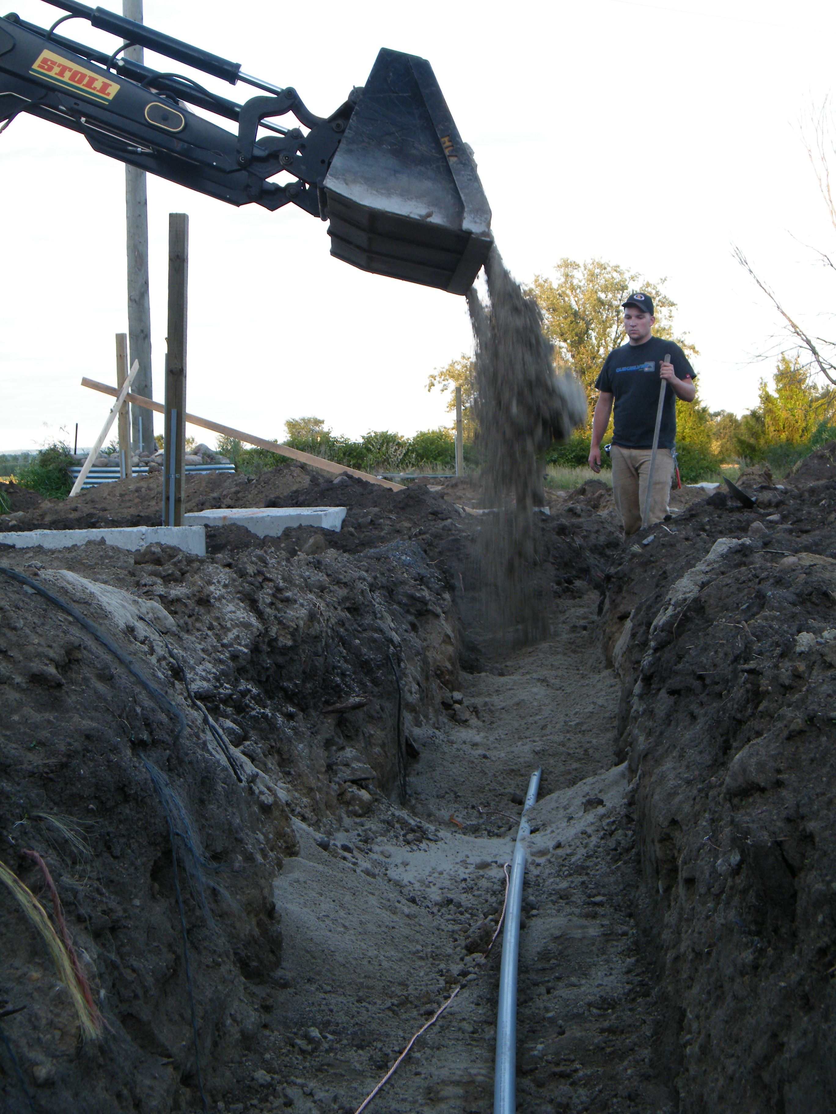
Glen Gordon's Pseudo Polar Axis Tripod Mounts.
He has 7 of these, WOW!!! They are VERY nicely done. They look very strong compared to mounting on top of a post.
He is tracking each of them with an LED3XS24Vc3P and driving each 24V C-Band linear actuator from 12V to slow them down.
Seasonal adjustment of the Pseudo Polar axis is accomplished by changing the high end mounting height.
Robert Brown's Tripod Polar Tracking Mount
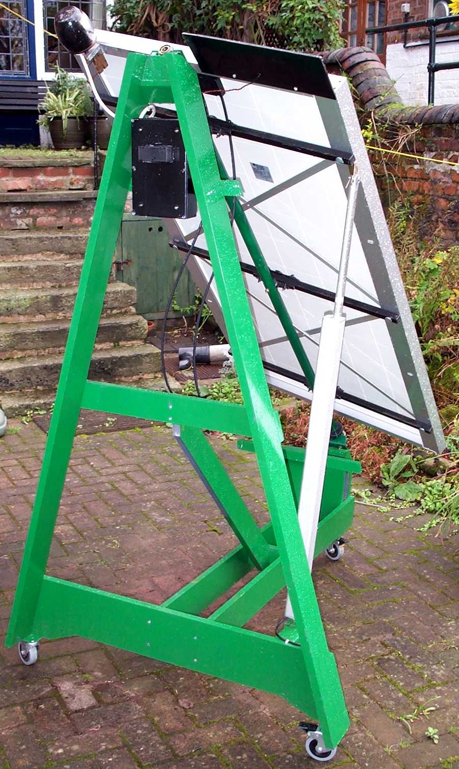
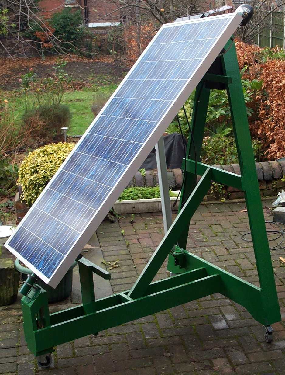
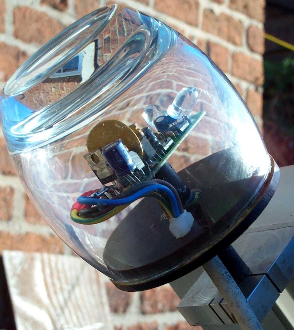
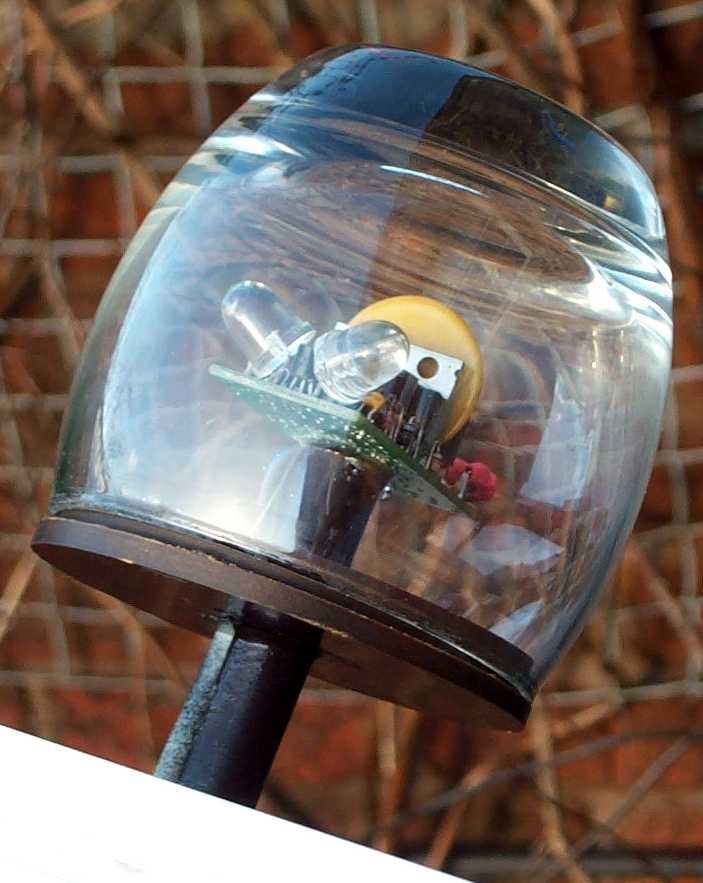
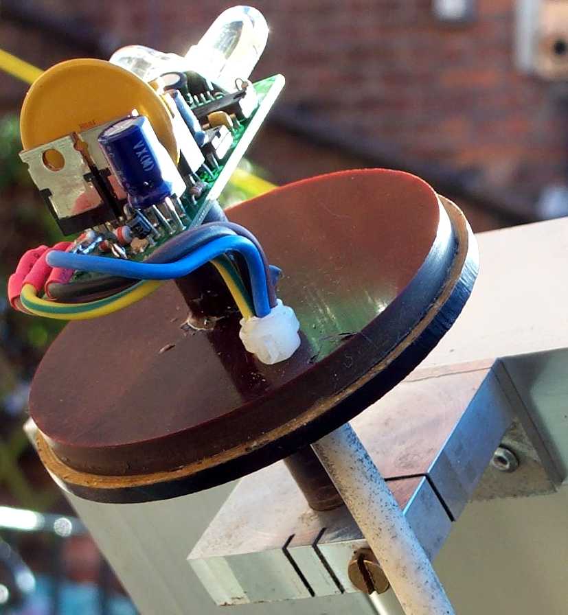
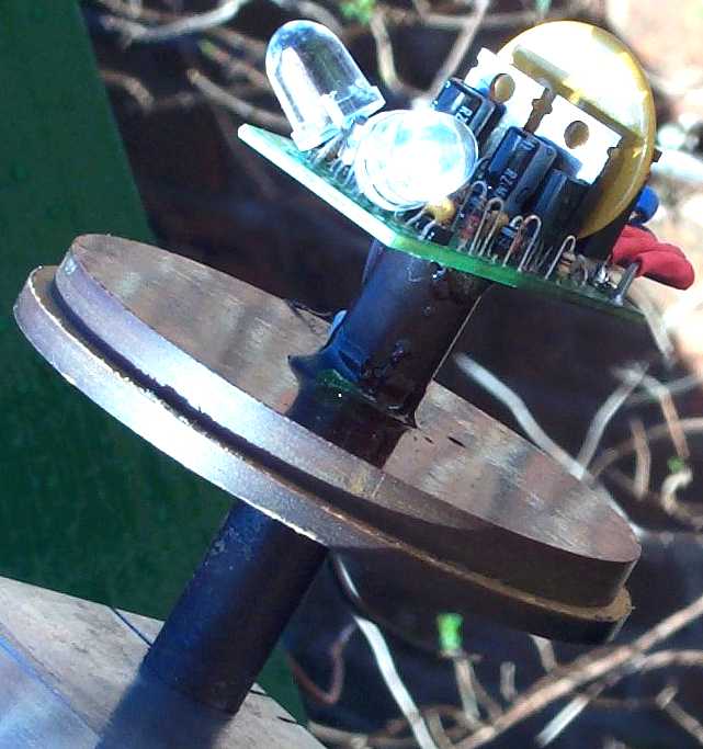
Robert Brown lives in the UK. His mount is loosly based on the polar axis designs of Martin Poulek's Traxle Tripod mounts.
1. Strait up, roughly along the power MOSFETs.
2. Strait down from the bottom of the board.
3. Forward mounted under the board.
4. Rearward mounted under the board.
5. Or no connector at all, just 12", ( or any other length ), wire pigtails.
6. And the standard, mounted rearward on top of the board.
Walter Simmons' PV Pseudo Polar Axis Mount
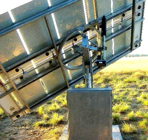
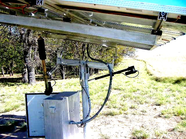
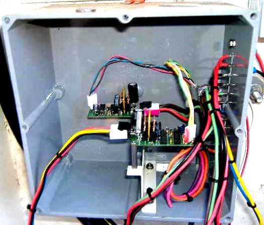
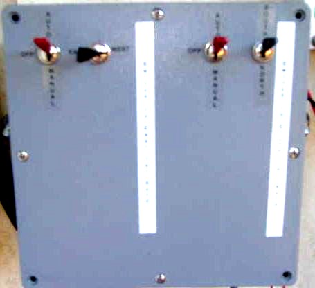
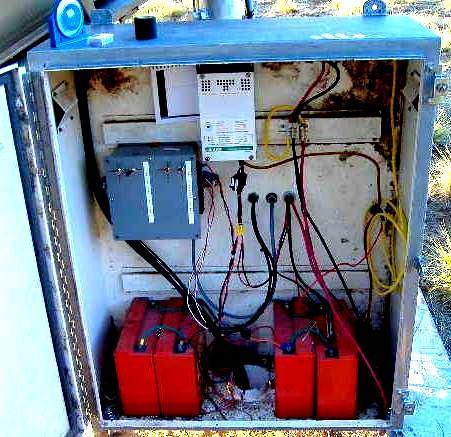
This uses a dual axis LED3X in the old C-based electric meter enclosure.
It has ten 48v 42w panels and four 12v 15w panels mounted on the array.
Two of the 15W panels supply power for the tracker and two charge his generator starting batteries
He lives in Texas.
Paul Roberts's Satellite Dish Pseudo Polar Axis Tracking Mount.
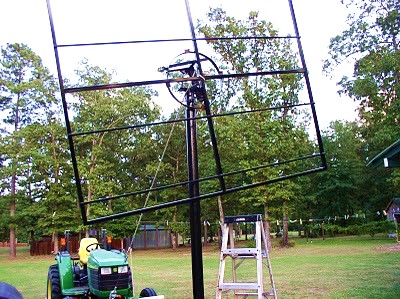
Paul has a blog describing how he's constructing his solar tracking mount, based on a satellite dish mount, which will be a grid tied system.
He's using an LED3XS24Vc3P standard single axis tracker.
Marshall Taylor's Semi Portable PV Mount based on a Satellite Dish Pseudo Polar Axis Tracking Mount.
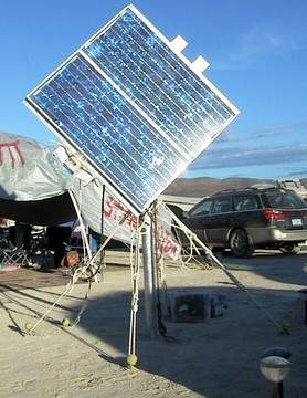
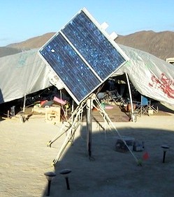
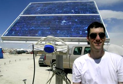
Marshal setup this PV system at the 2004 Burning Man Festival.
This uses an LED3XS24Vc3P in the jar.
This mount originally was a C-band satellite dish mount.
<marshall@perilith.com>
Joel Wylan's Array of Satellite Dish Pseudo Polar Axis Tracking Mounts.
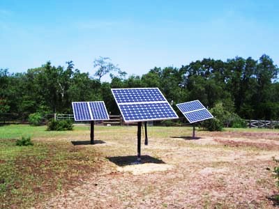
Joel, from Florida, made these from old C-band satellite dish mounts.
Jim Parish's Pseudo Polar Axis Tracking Mount based on Satellite Dish Mounts.
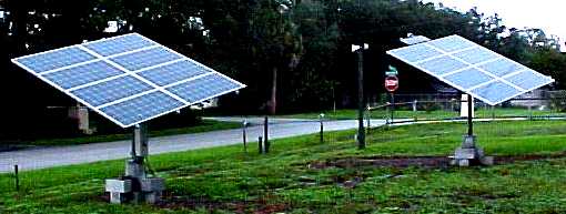
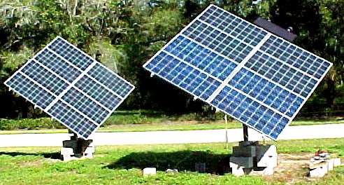
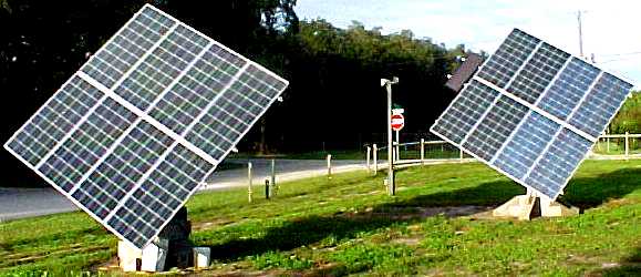
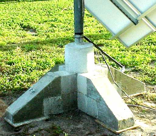
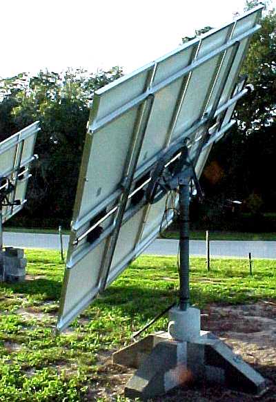
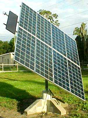
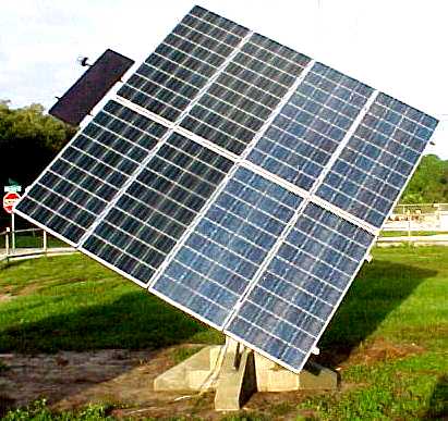
The tracker is made from old C-band satellite dish mount.
Jim is using the standard single axis LED3XS24Vc3P trackers.
Note! The concrete block bases do not anchor the pole mounts sufficiently to the Earth. Several of these were over turned in high strait line winds. Thankfully none of the PV panels were dammaged.
Roberto Flores' Pseudo Polar Axis Tracking Mount based on a Satellite Dish Mount.
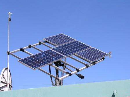
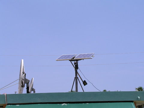
The tracker is made from old C-band satellite dish parts, a 24 inchs actuator on a pseudo polar axis mount.
<roberto_fm@hotmail.com>
Volvo Farmer's Satellite Dish Pseudo Polar Axis Tracking Mount
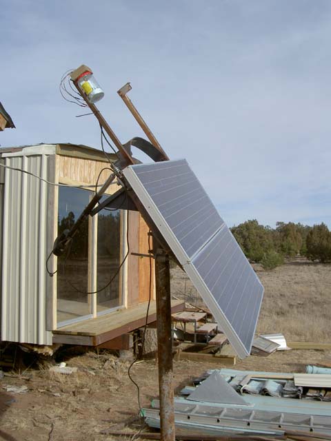
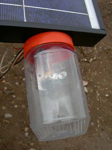
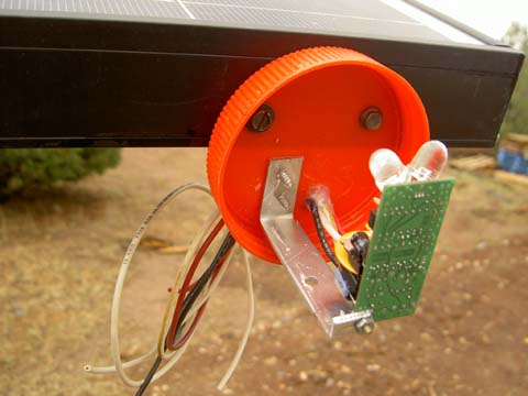
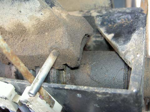
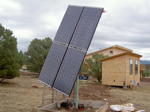
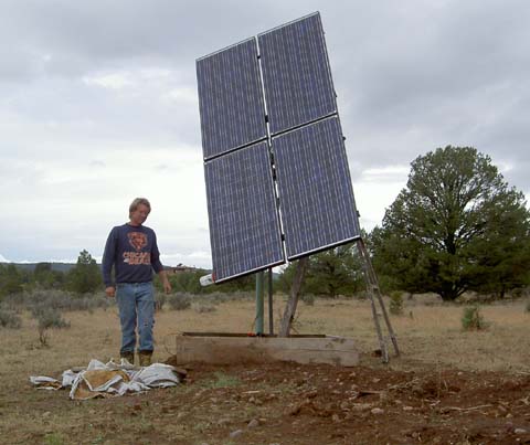
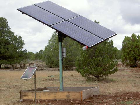
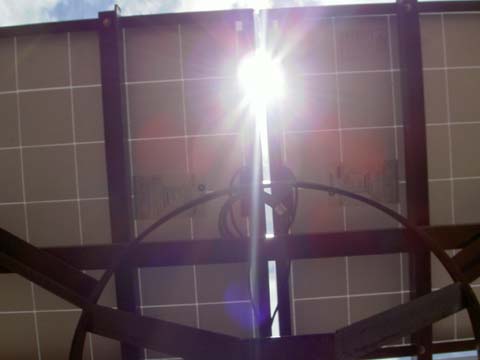
Volvo Farmers C-band satellite dish based pseudo polar axis tracking mount.
See the story here:
http://www.fieldlines.com/story/2006/3/6/12351/04204
http://www.fieldlines.com/story/2006/7/8/20847/11730
djpitr's Pseudo Polar Axis Tracking Mount based on a Satellite Dish Mount.
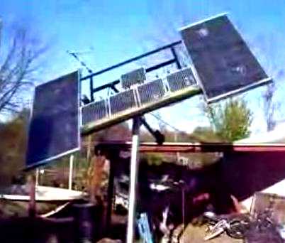
He is using an LED3XS24Vc3P single axis tracker.
djpitr made a YouTube video showing his system.
Tracking throughout the day
A heliostat in the works
scrapit85's Pseudo Polar Axis Tracking Mount based on a Satellite Dish Mount.
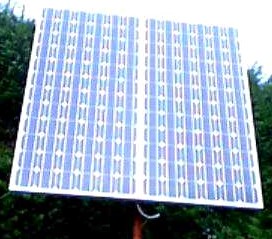
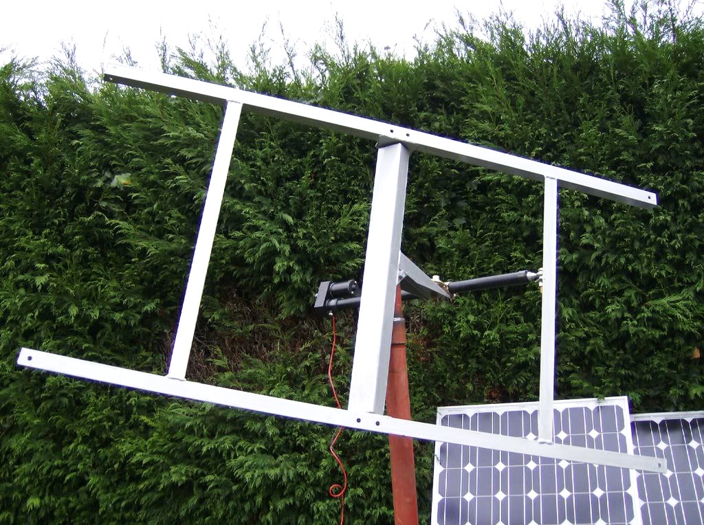
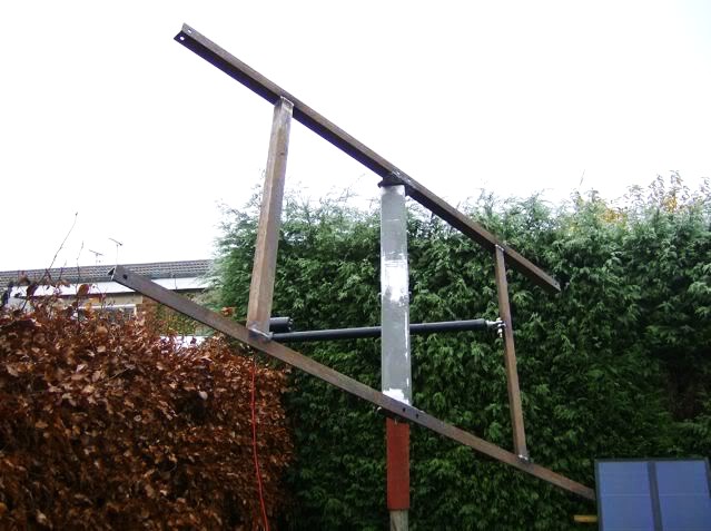
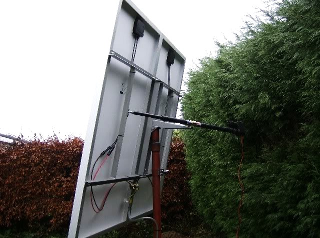
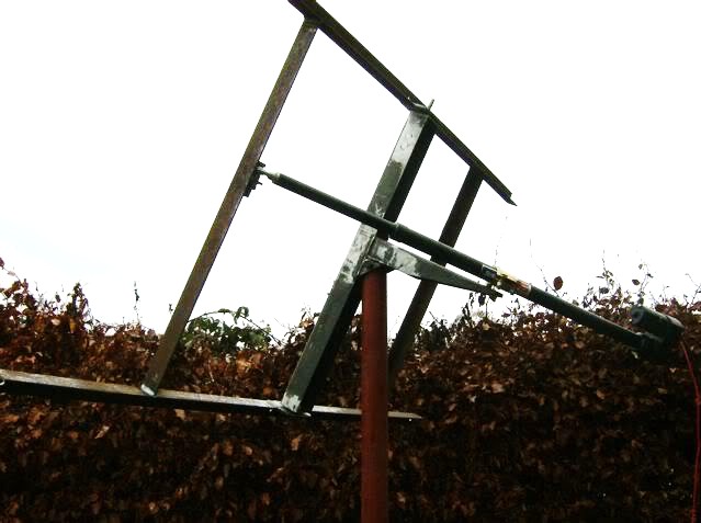
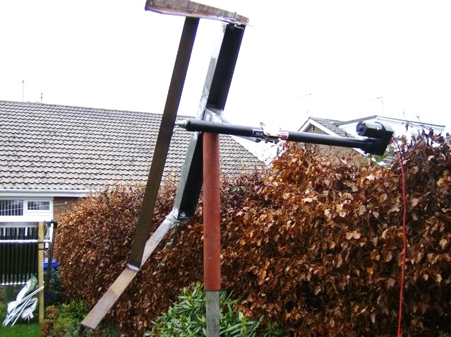
scrapit85 made a YouTube video showing his system.
Alexandre Moleiro's PV Pseudo Polar Axis Mount based on a Satellite Dish Mount.
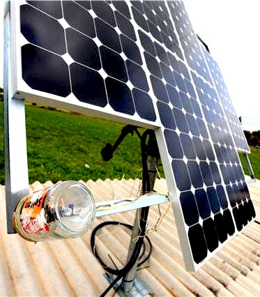
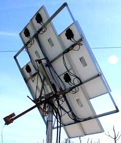
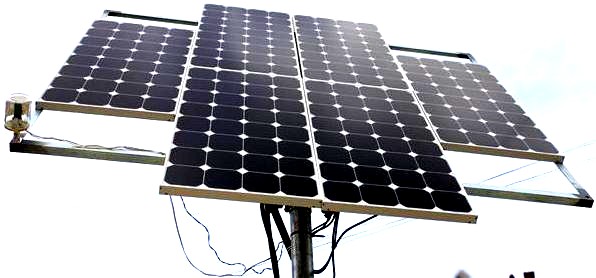
This is an old 1.8m satellite dish mount with some minor modifications. He made a drawing for the rack and mast and had it made by a local welder.
garrison
Steve Garrison's Vertical Axis Tracking Mount based on a Satellite Dish Mount.
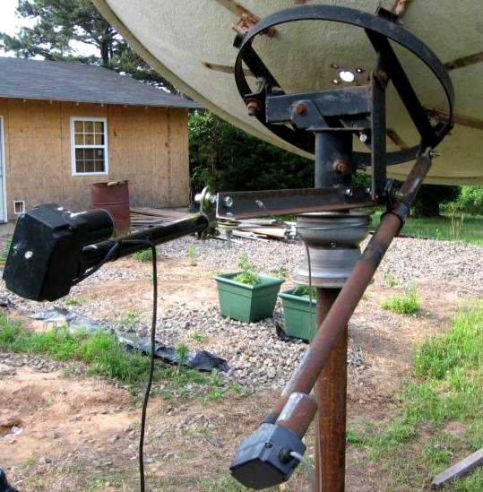
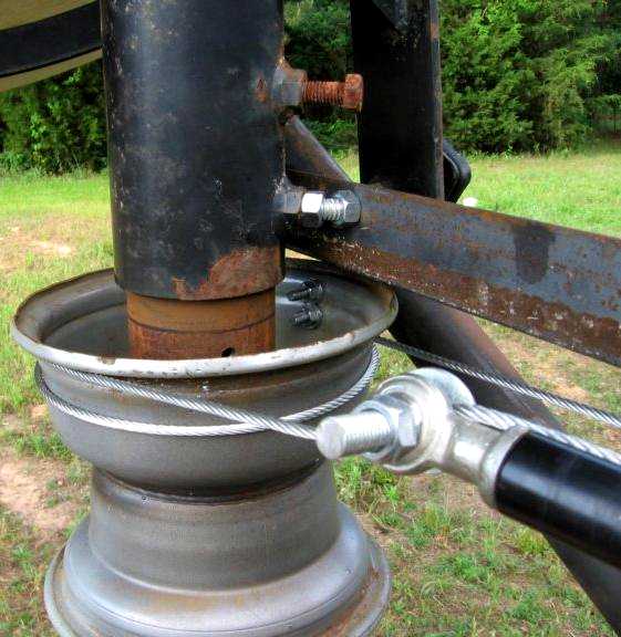
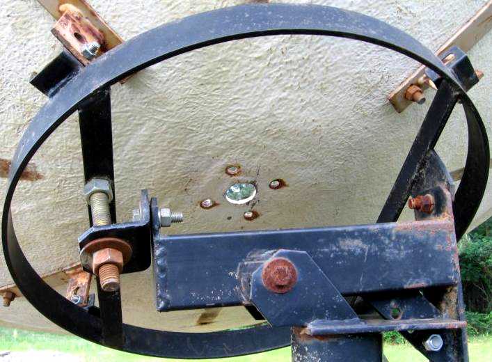
This is a Vertical Axis mount.
Andrew Thompson's 4KW Array of Vertical Axis Tracking Mounts.
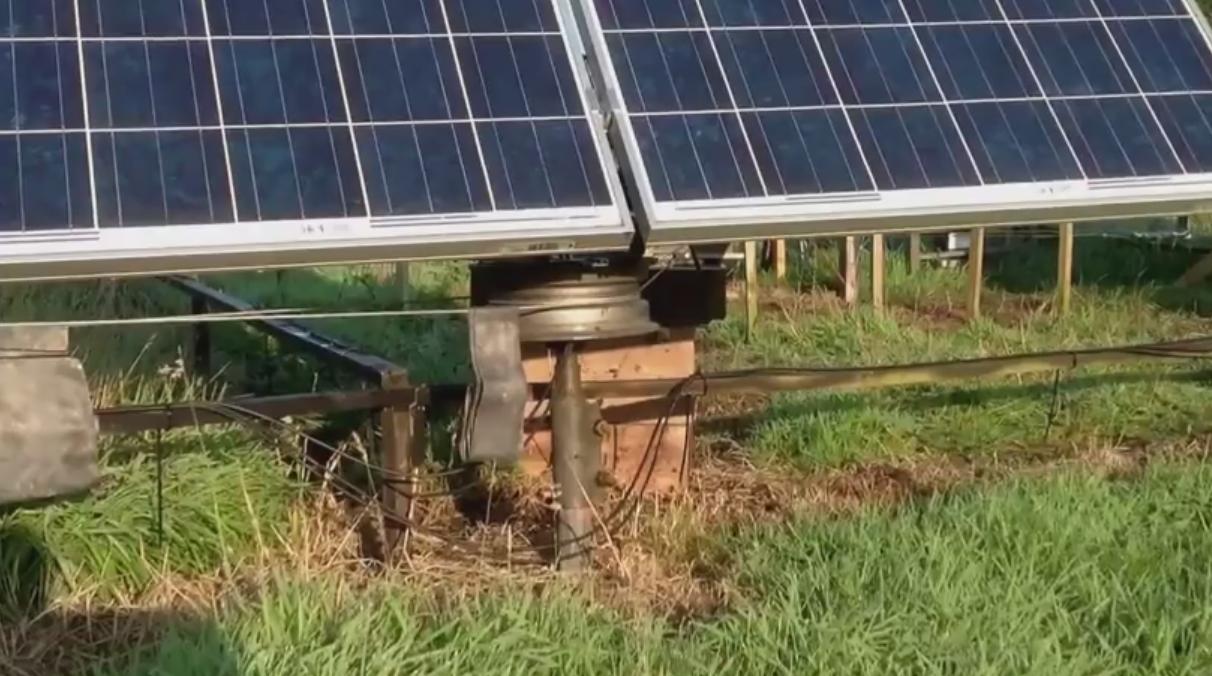
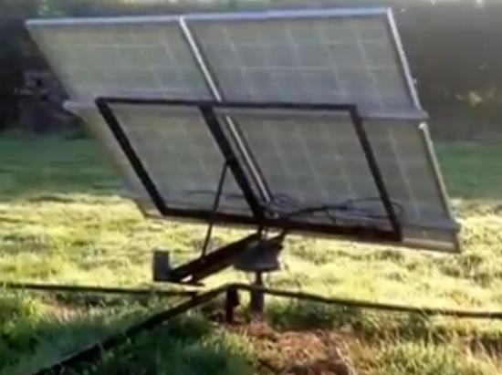
notasprocket
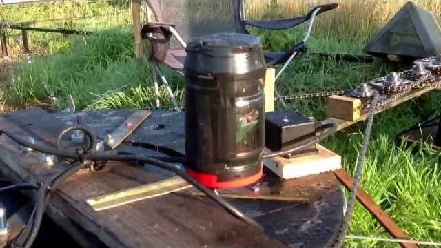
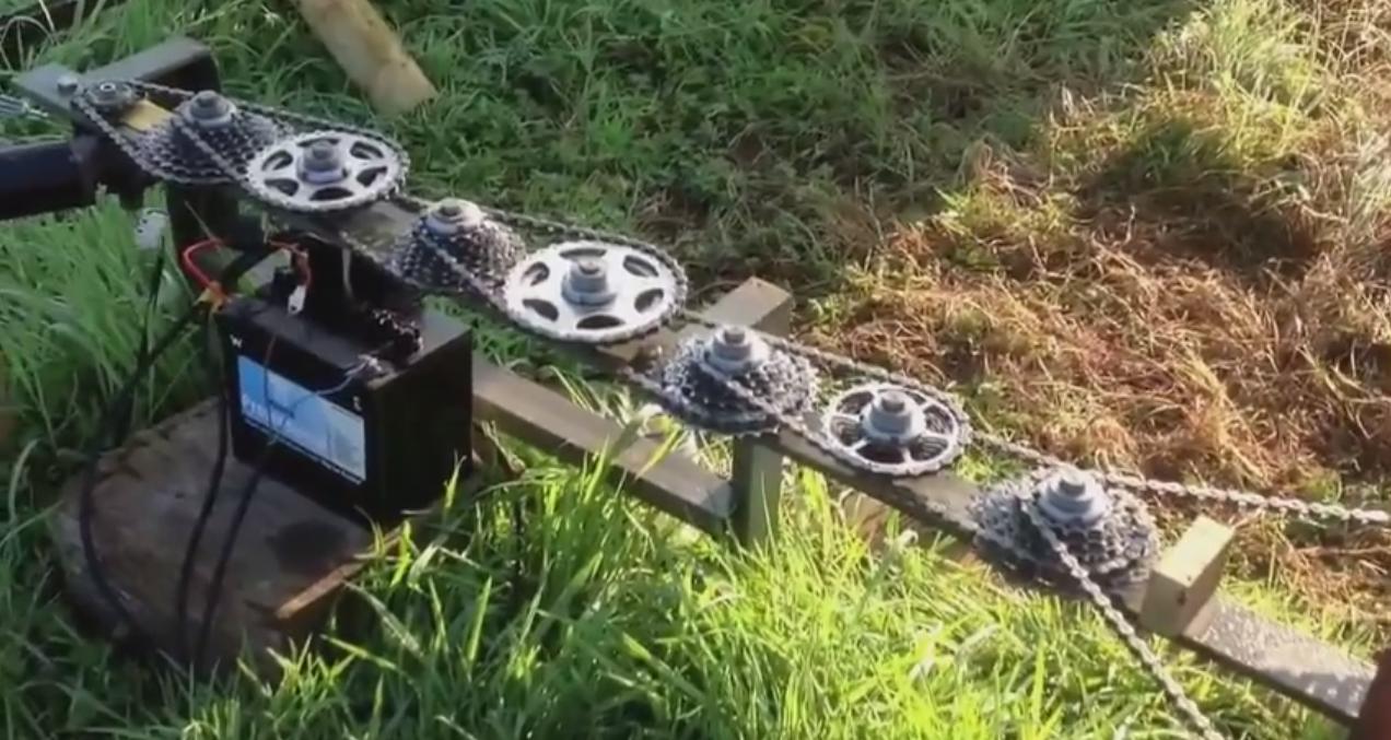
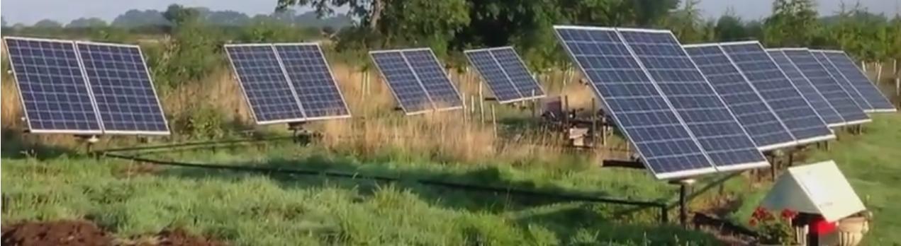
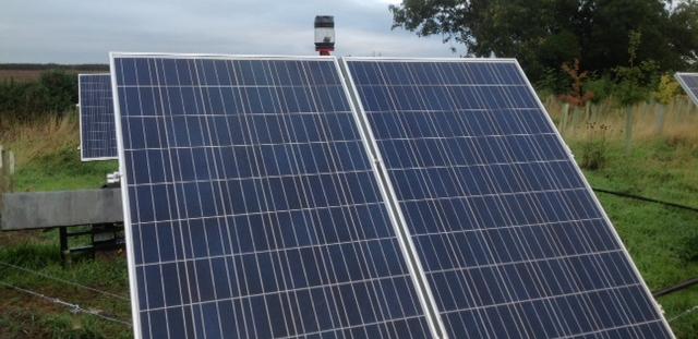
Andrew is located in England at a latitude of about 54°North.
1. Suzuki gearbox = 40/1 (my guess)
2. 7 derailleurs, 32/13 * 32/13 * 26/13 * 34/14 * 26/19 * 25/14 * 24/19 = 90.8/1
3. Final "Not A Sprocket" = 16.2/1
40/1 * 90.8/1 * 16.2/1 = 58865/1 Total NICE!!!
or calculated a different way:
1. Suzuki gearbox = 50 rpm = 72,000rpd (revolutions per day)
2. 72000rpd / 90.8/1 / 16.2/1 = 49rpd
Andrew reports it takes about 25 minutes to rotate about 200 degrees. The last 2 derailleurs look like they are not at the maximum reduction. Also some appear to be crank derailleurs.
Andrew's email address: <struck2soon@tiscali.co.uk>
1. This arrangement of multiple tracking mounts linked by cables is "HIGHLY SIGNIFICANT" and can be adapted to many other tracking mount types. Such as the Tripod Tracking Mounts.
2. The orientation of the master cable drive must be the same as the multiple tracking mounts if the tracker is mounted on it.
3. An improvement would be to orient the master and tracking mounts to the "Polar Axis". In Andrews case the main axis would be tilted up from the horizon on the north by 54° and tracked in RIght ASCension. Now, the manual secondary axis would be close to ideal when adjusted only 4 times per year.
decadjust
See my excel spreadsheet "decadjust" for the proper dates to set the DEClination angles:
February 21st to April    21st =   0° of DEClination for 2 months
April    21st to August   21st = +12° of DEClination for 4 months
August   21st to October  21st =   0° of DEClination for 2 months
October  21st to February 21st = -12° of DEClination for 4 months
Doing this one can gain about 5% as opposed the 7% by actively tracking DEClination with a polar axis tracking mount. 4 times per year is easy to do, or simply set the declination to 0° and leave it alone. The great majority of energy gain per year is in tracking RIght ASCension.
Dan West's Tracking Mount
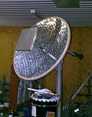
I've started with my prototype using a 4.6' dish covered with 2" mirrors. The collector is a little oversize to the square footage of the dish but I've already got plans to go up to the 10 and 12' dish.
<danwest@missvalley.com>
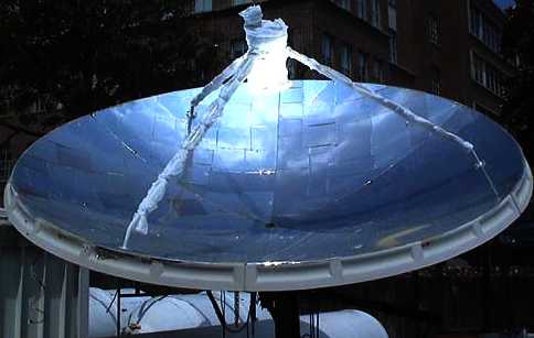
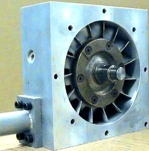
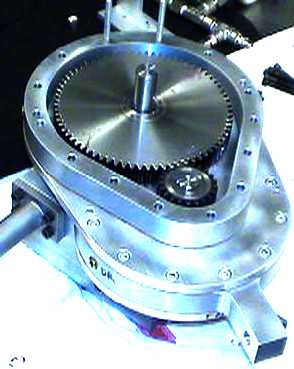
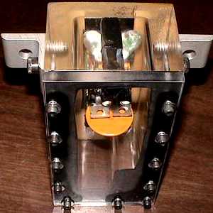
* C. Christopher Newton
This is a beautiful example of a Solar Dish Steam Turbine Electric Generator.
This was his masters thesis project.
Attached is a copy of his thesis paper which is on a concentrated solar thermal steam system.
In the appendices of the paper, you will find the diagrams for the steam turbine.
With the proper amount of steam supplied, the turbine is capable of about 5 hp.
Geotrack Horizon to Horizon Satellite Dish mount.
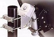
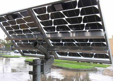
cclancy1, Australia, sent me these photos of a single axis mount based on a Geotrack H-H satellite dish mount. I have not had one of these in my hands yet, but I'm told that they have the required limit switches. They should work fine as long as the wind loading is not exceeded to badly. The one in the picture was designed for a 1 meter, 3.25', dish which is about 5 square foot of area. I think the one in the picture is a bit larger than this.
Paul Cross' Horizon to Horizon Satellite Dish mount.
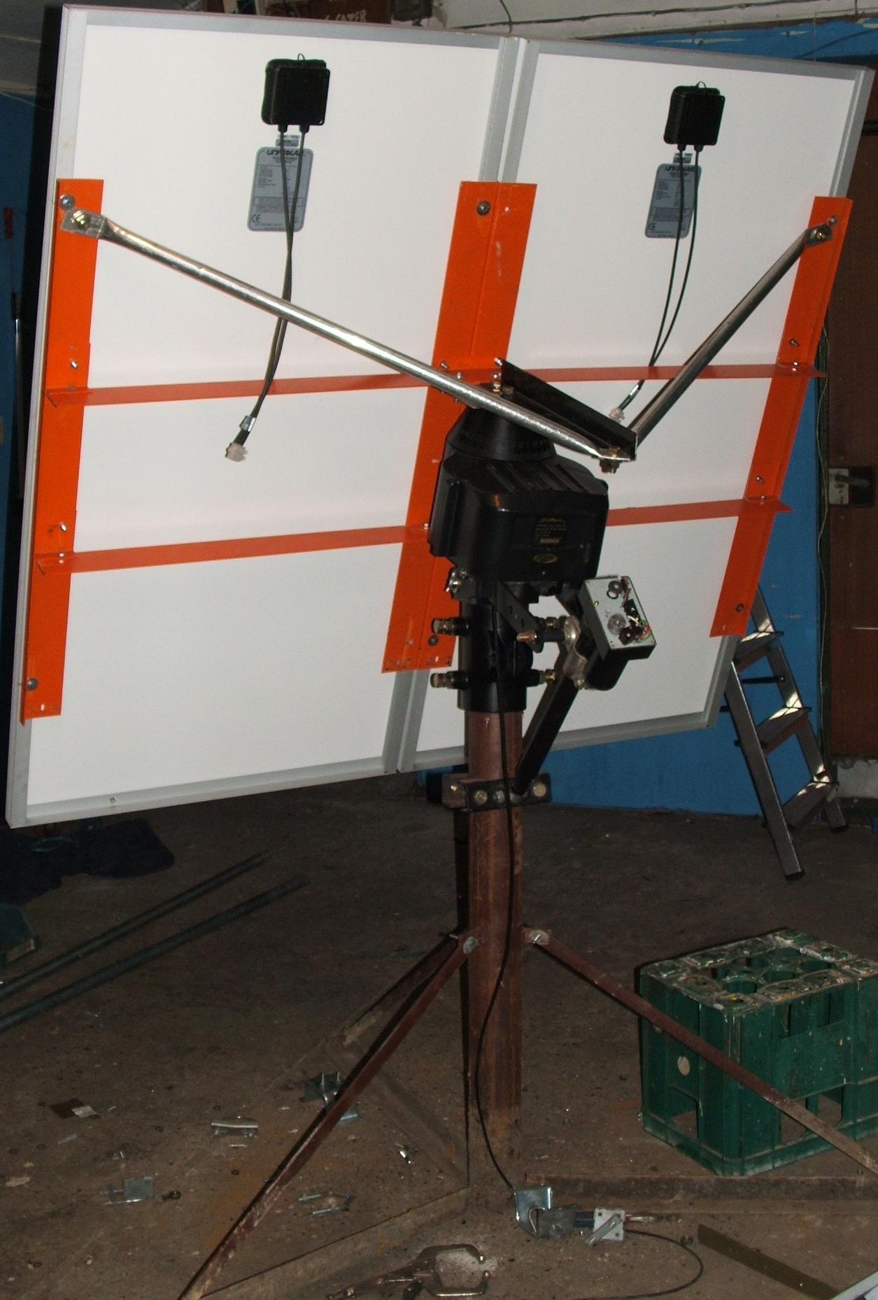
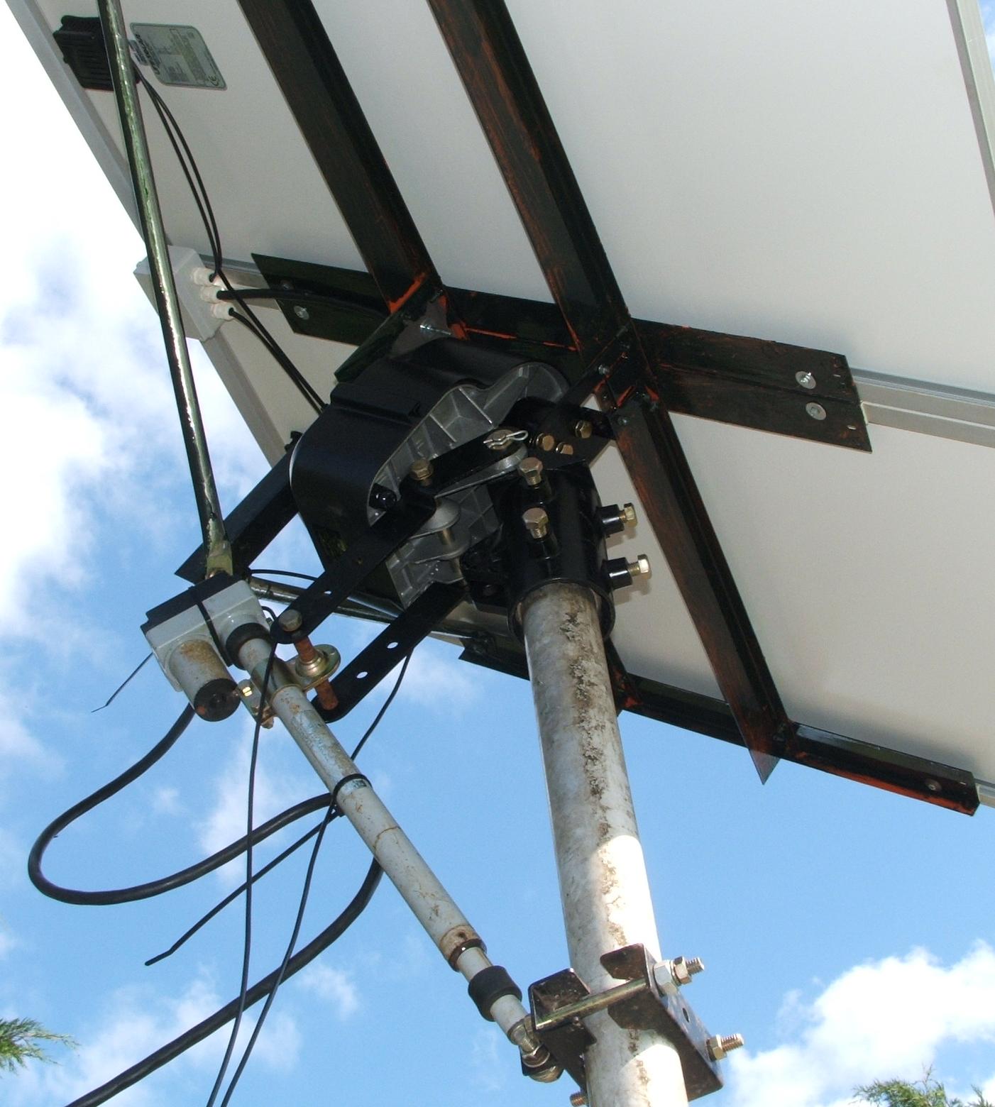
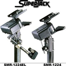
Paul has a large Horizon to Horizon Satellite Dish mount. It's a Jaeger SMO-36 and is good for a 2.4 to 3.6 meter dish, I don't think it's made anymore. It's similar to the SMR-1224EL (1.2-2.4m). Paul is initially going to use a single axis tracker and manually adjust the DEClination axis electricly.
http://www.jaeger.com.tw/tvro/superjack/mount_superjack.htm#1224
Jory Schwach's Polar Tracking Mount
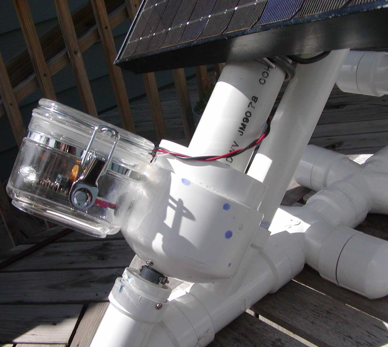
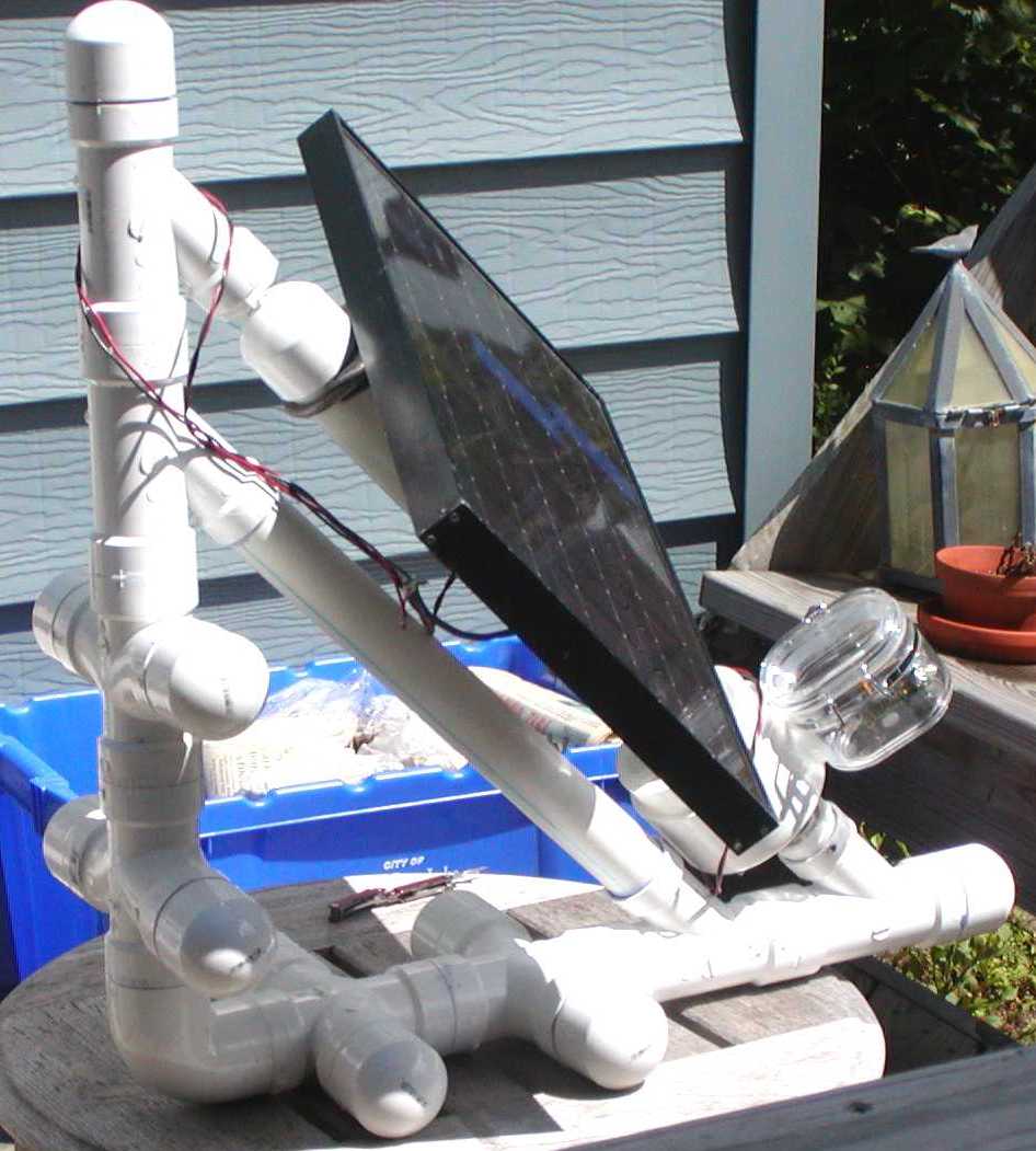
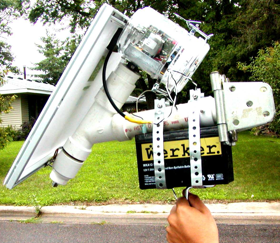
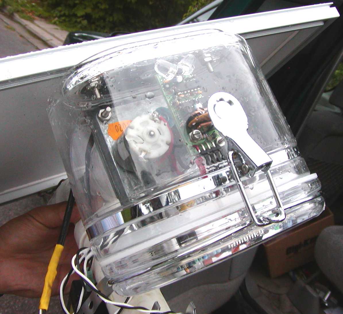
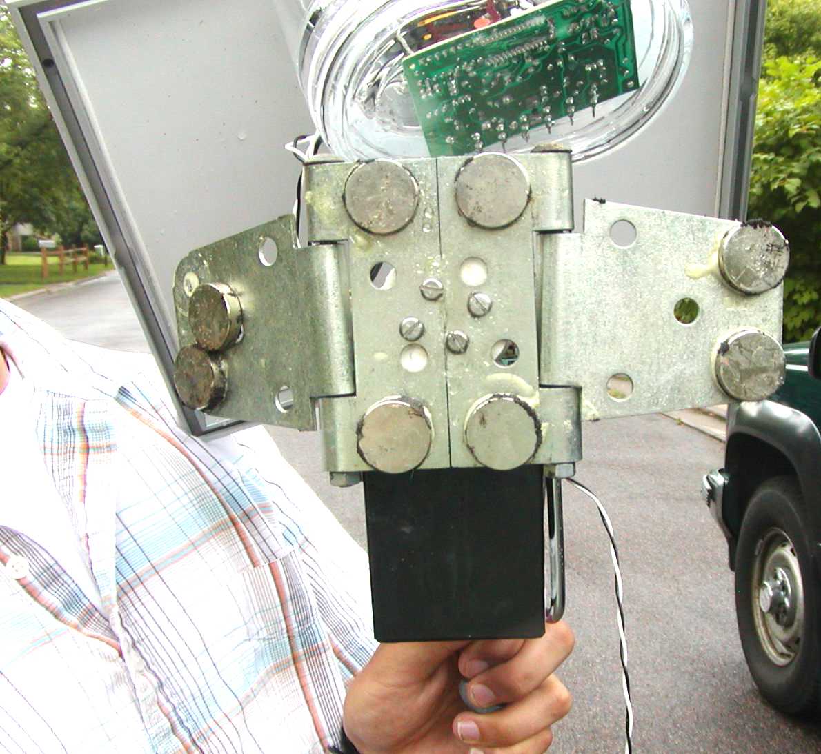
Jory is a college student at the University of Minnesota. He is working on a project to power a very cool Panasonic digital camera. This camera in linked to the Internet using WiFi. The basic application is for counting traffic at intersections. The counting is done using DSP software with a master computer any where in the world. The mount is to be attached to semaphore poles using magnets.
The DC gear motors have built in limit switches. They are from vending machines, the type that spits out candy and rolls with a large spiral wire. I like these because they have a plastic cam and switches. All the hardware is there. The plastic cam can be carved to obtain any desired limit position.
Cool huh!!!
<jschwach@gmail.com>
dm2100
dg240
dg280
Small Polar Tracking Mount based on the Sadoun DG-240 H-H Mount
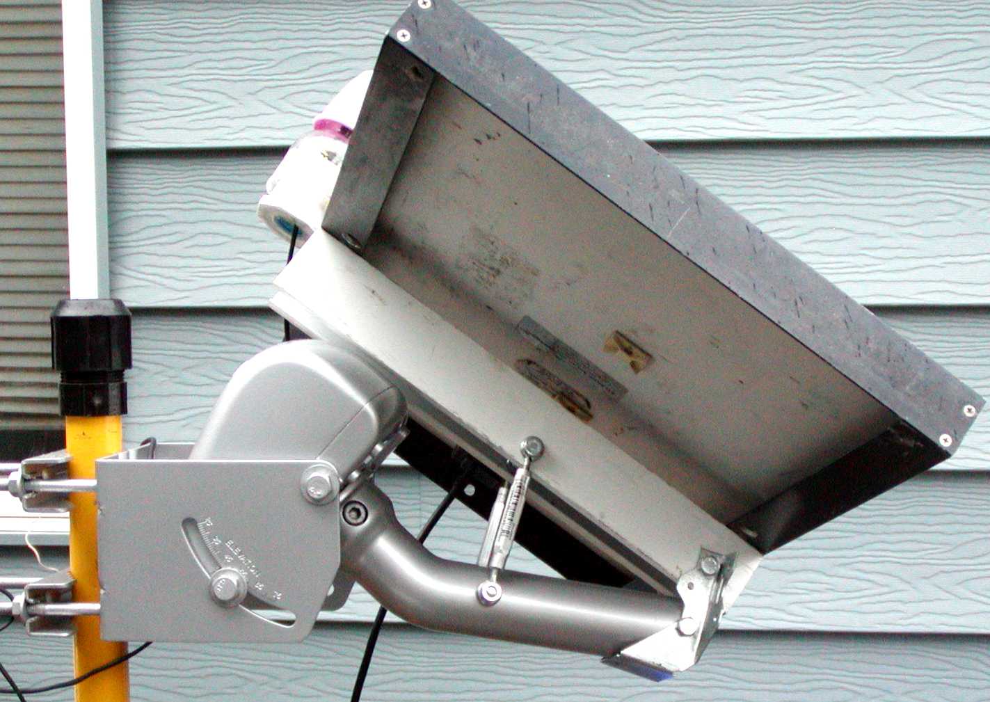
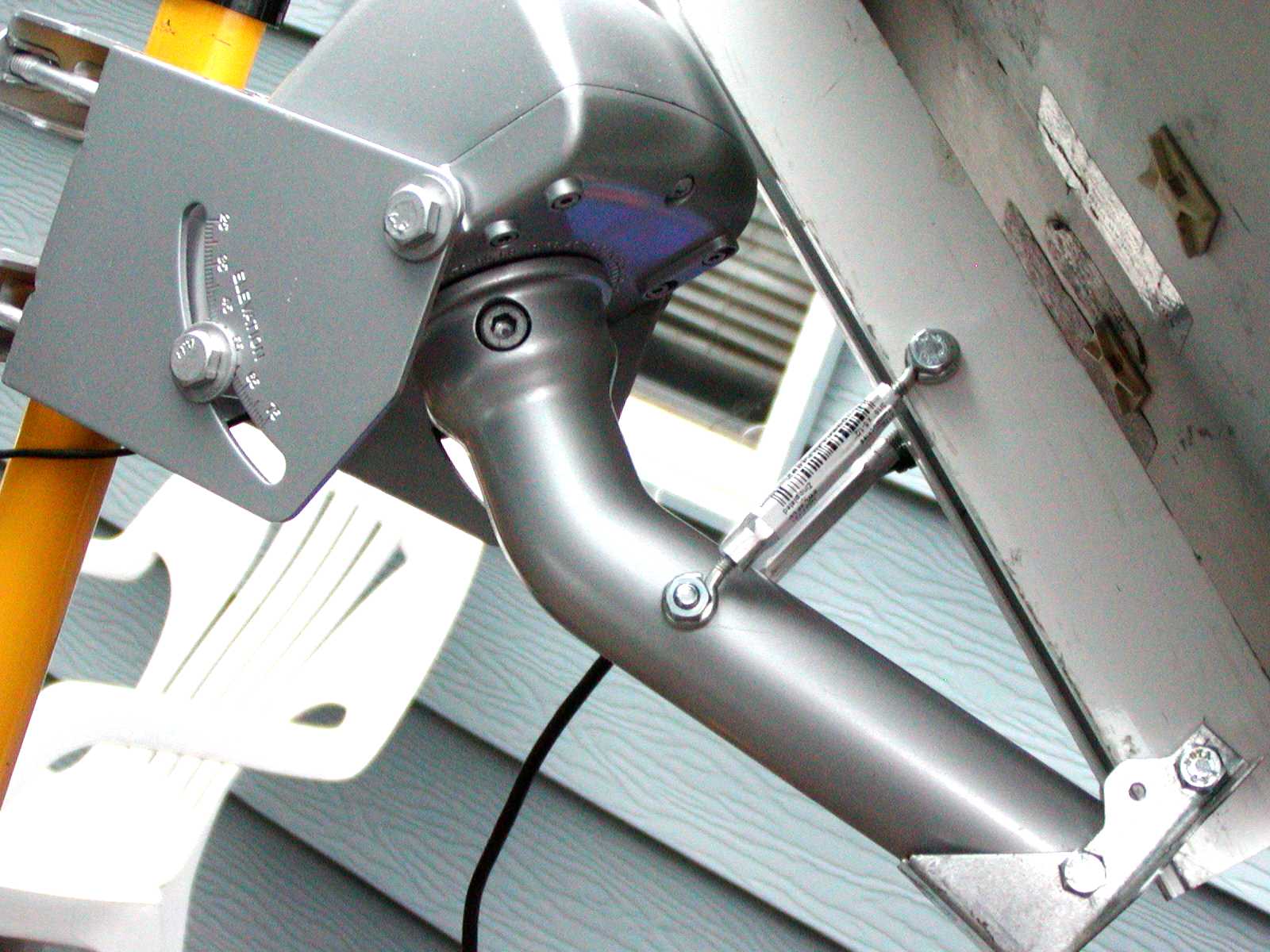
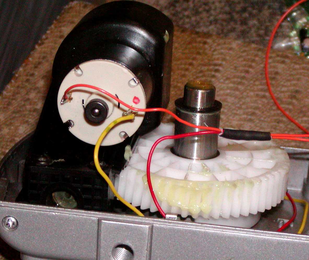
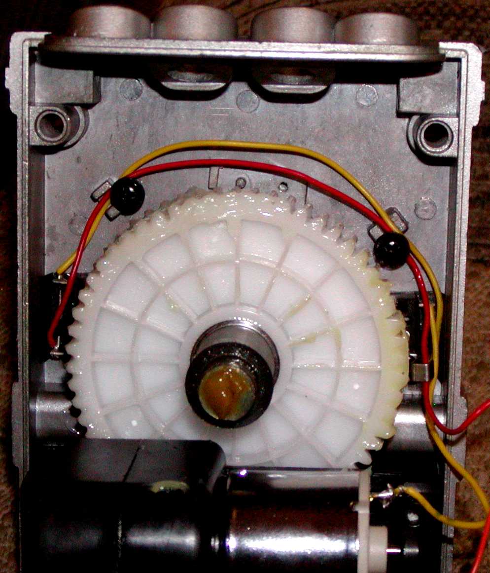
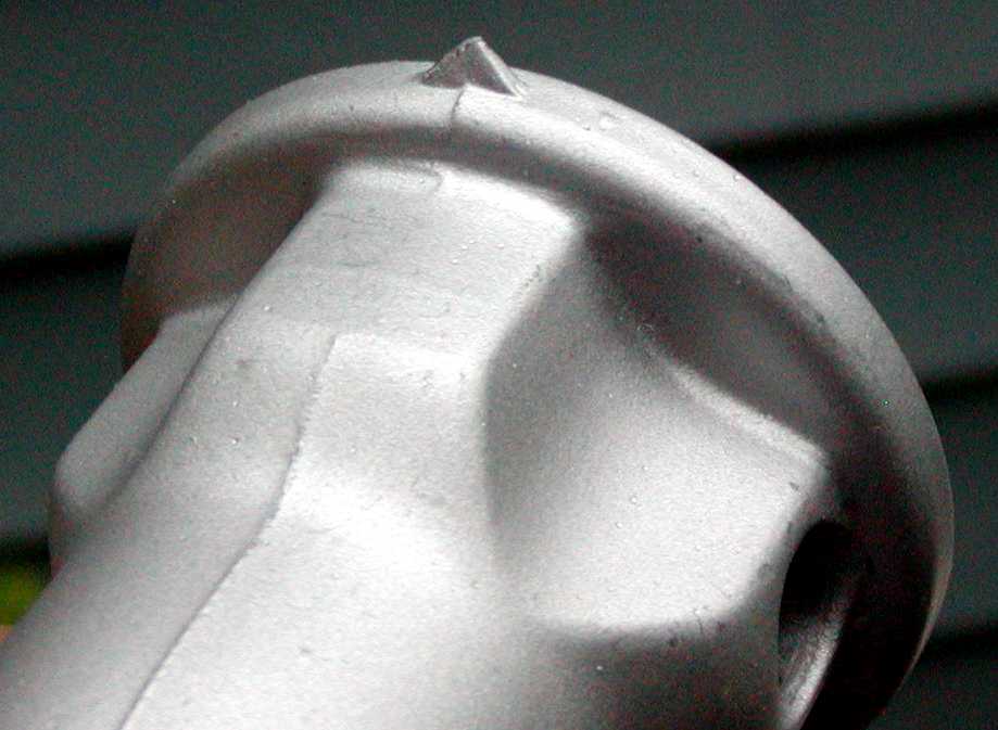
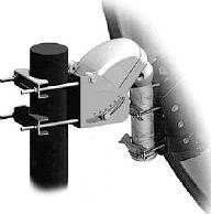
This mount system is suitable for relativly small tracked PV panels.
Sadoun DG240 About $70 + shipping from Sadoun.
Note! The DG240 is no longer available so use the DG280 instead.
Sadoun DG280 About $90 + shipping from Sadoun.
Sadoun DG280B About $80 + shipping from Sadoun.
Note! The worm gear in the SG2100 I have is not complete. It is a sector of a full gear, the DG240 has a full gear so it can rotate a full 360°s if required.
An idea on how to mount a PV Panel on a boat.
![]()
I got this idea about how to suspend a PV Panel on a sail boat from the mast. The tracking is done between the wind vane tail and the panel. The swivels also serve as slip rings.
Ricard Pardell's ALT/AZ Tracking Mount
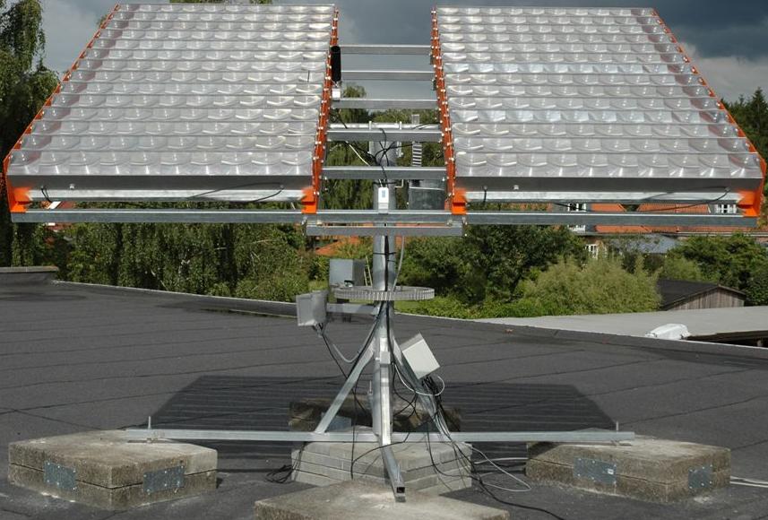
Ok, I didn't supply the tracker, although I could have.
But seriously, take a look at the cool large size gears on this ALT/AZ mount.
oops
Oops
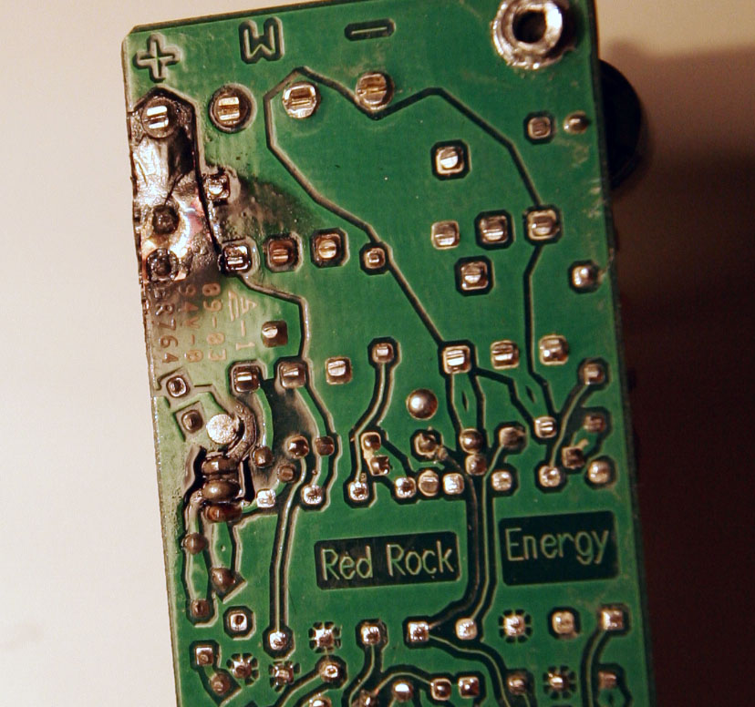

An example of what can happen when the power is reversed on this "c1" tracker.
Don't do this!!!
Another Oops
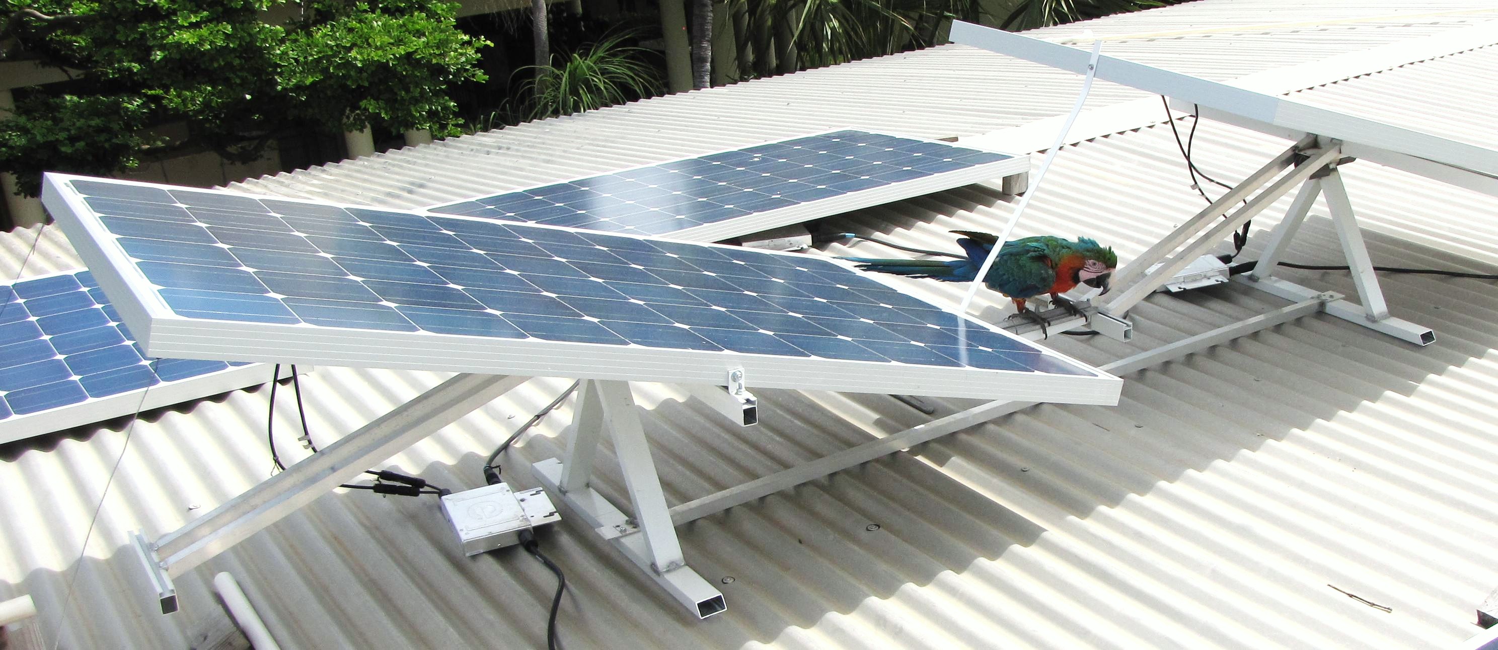
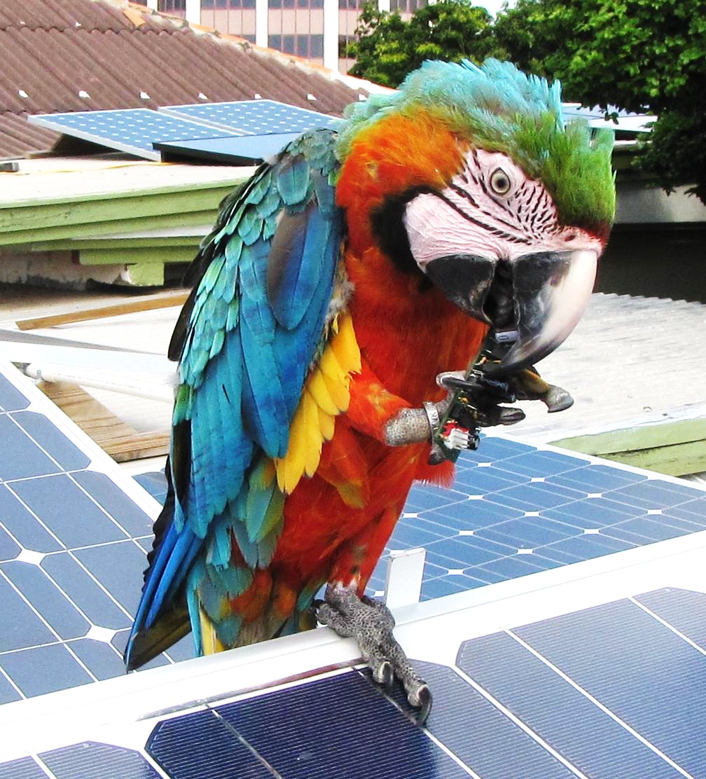
Keep away from Parrots in Aruba!!!
And Another Oops
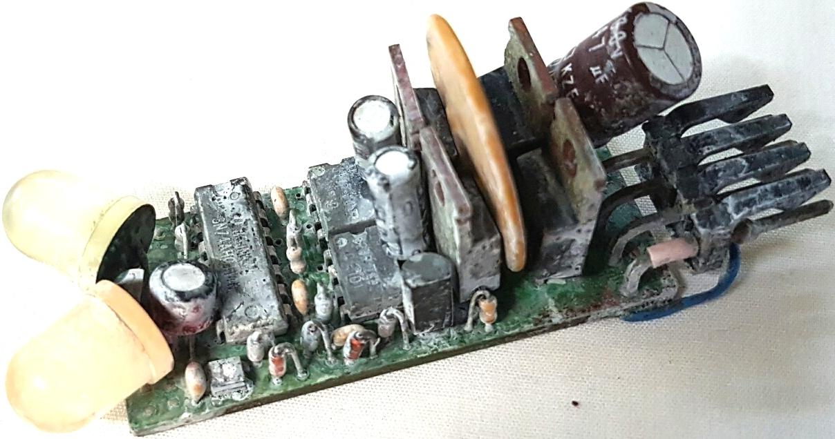
Tracker Drowned in Water!!!
Andre in Aruba wrote this:
"Hi Duane, You made a joke about fixing that unit, but why would you want to fix it if it ain't broke. I saw you posted the picture in the OOPS section. I think you should also add to that picture that as messed up as the unit is still on my roof tracking the sun as I am writing this. There was just a bad contact in the connector plug. You should be very proud of that unit."
This is Cool
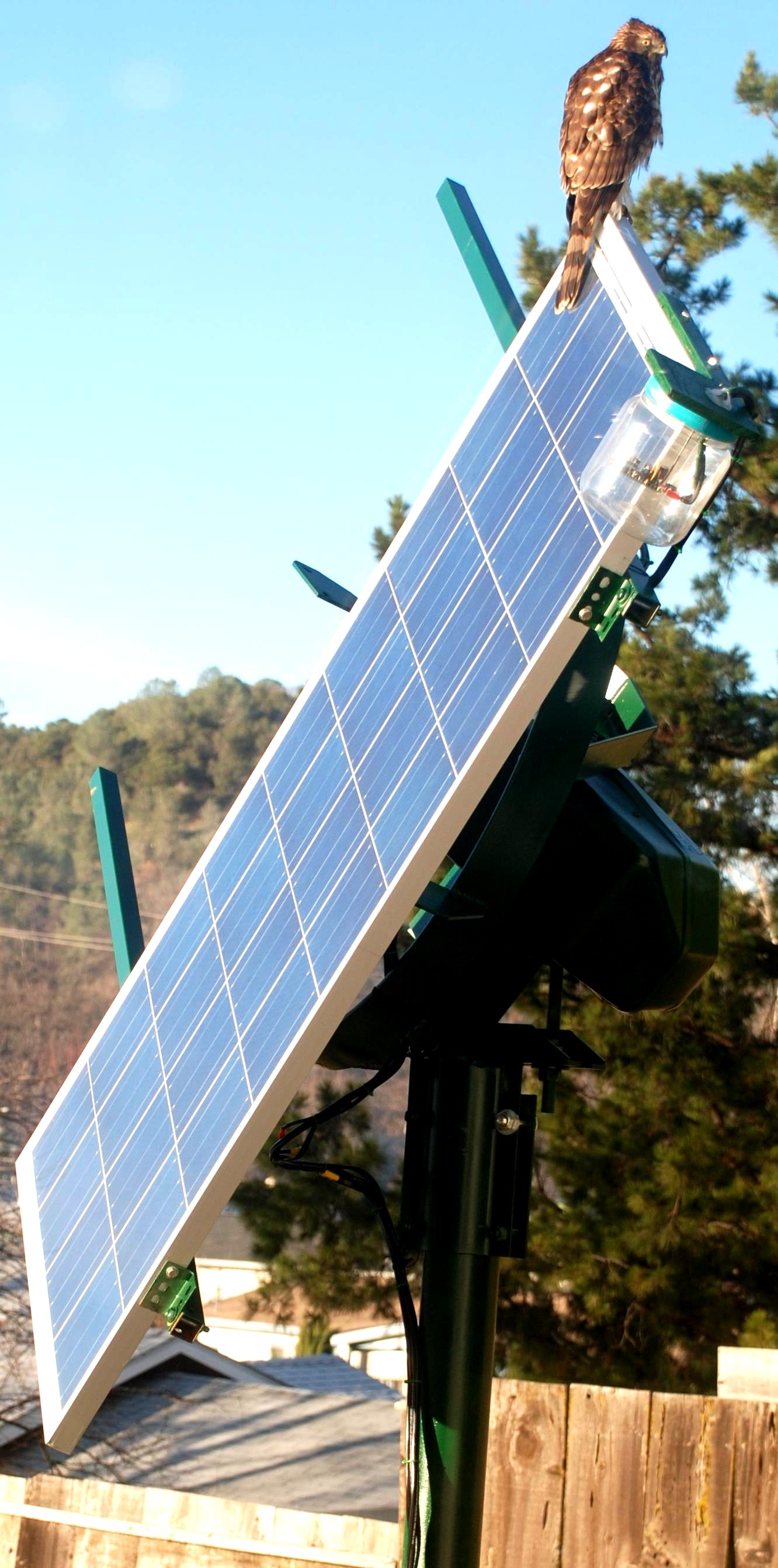
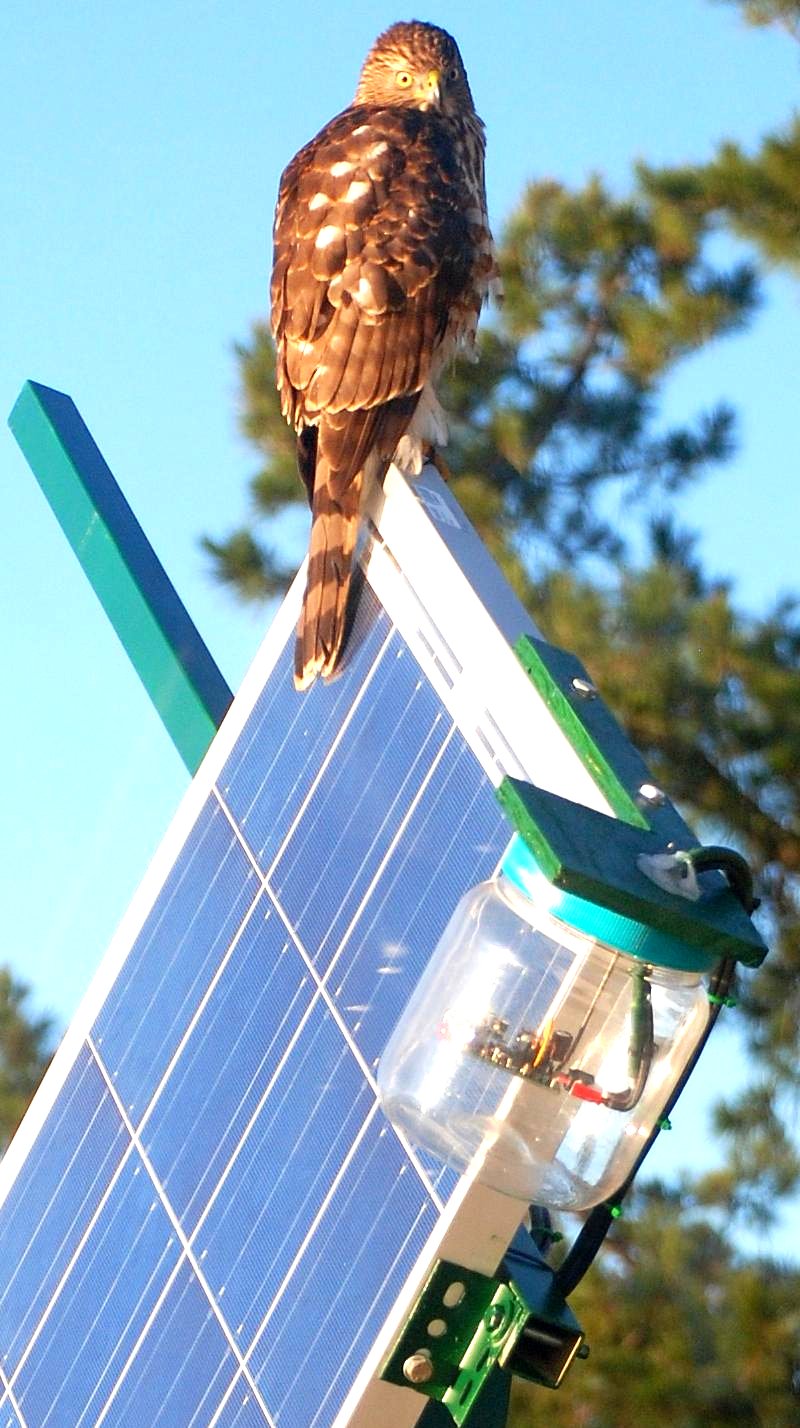
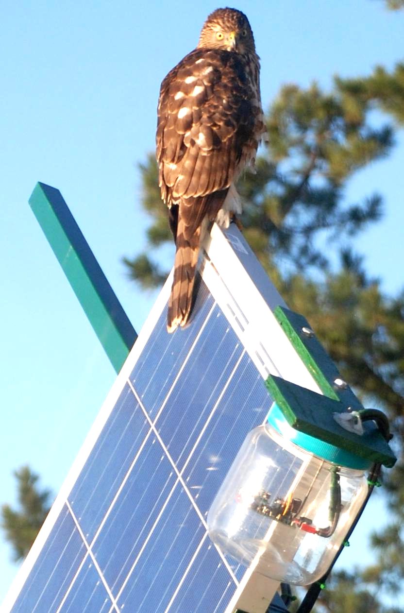
This is an impressive picture!!
BTW, I feel the weather dome is mounted upside down.
If there is a leak in the seals the dome can fill up with water.
led3xc3mods
LED3X Modifications
npmod
1. NP, No Parking. If you don't want the tracker to park, possibly for the vertical axis on a 2 axis dish or a boat or RV application as with Wolfgang. Note! The NP feature is an option built into the RM, ReMote sensors. See below.
rsmod
2. RS, Remote Shutdown, forces the tracker to move off track. This might be connected to a thermostat or relay contact to control baking temperatures in a solar oven where fairly fast control is required. When the contacts are closed tracking is normal. Open the contact and the motion goes off track. $10us plus $4us shipping.
Note! On the standard tracker off track is toward the PARK position. On ReMote sensor versions off track is toward the FORWARD position.
Note! Reverse Inhibit should not be used in thermostaticly controlled systems.
RS is best used as an over temperature shut down.
Normal thermostat control is best done with the limit switch circuits.
rimod
3. RI, Reverse Inhibit, prevents moving in the opposite direction for about 3 minutes after an initial move in any direction. This is useful for motor drives that move to rapidly and tend to overshoot which causes "hunting" during the time the motors are moving. The RI is a small daughter PC board, about 0.5" x 0.65", added to the main LED3X circuit board. $10us plus $4us shipping. This can be added to either variation, the LED3X tracker or the LED3XRM power unit.
speed
OK guys, I can't stress this enough. The basic solution is to use SLOW permanent magnet DC motors drives.
We don't need fast speed.
We don't want fast speed.
We don't want high power motors.
What we want is a drive system with high gear ratios.
I suggest 100,000/1 or greater total gear ratios.
I like it to take about 1/2 an hour from stop to stop.
This is still moving 24 times faster than the Sun.
With high gear ratios the resultant forces can be quite high, even with relatively small motors.
See a You Tube clip of how the RI mod works:
 This is the action without RI.
Note the fast jittery motion due to hunting.
And the same system with RI.
The jittery motion is absent.
Ok, there is some movement due to shadows and clouds. This is normal.
4. LS, Limit Switch, allows the use of NO, Normally Open, low current "signaling" type of limit switches. The LS is a small daughter PC board added to the main LED3X circuit board. $10us plus $4us shipping.
Both RI and LS are on the same board. $15us plus $4us shipping.
Reverse Inhibit Installation
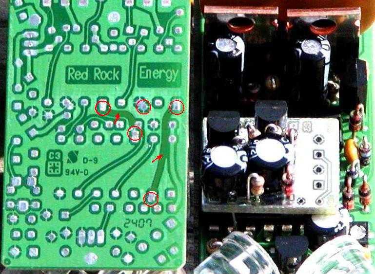
Click to enlarge image.
Remove solder from the 5 through hole pads indicated by the Red circles.
Cut the 2 foils indicated by the Red arrows.
Insert the leads from the RI board into the holes and solder.
Make sure the components under the PC board don't make contact with the standoff wires.
rm
LED3X ReMote sensor
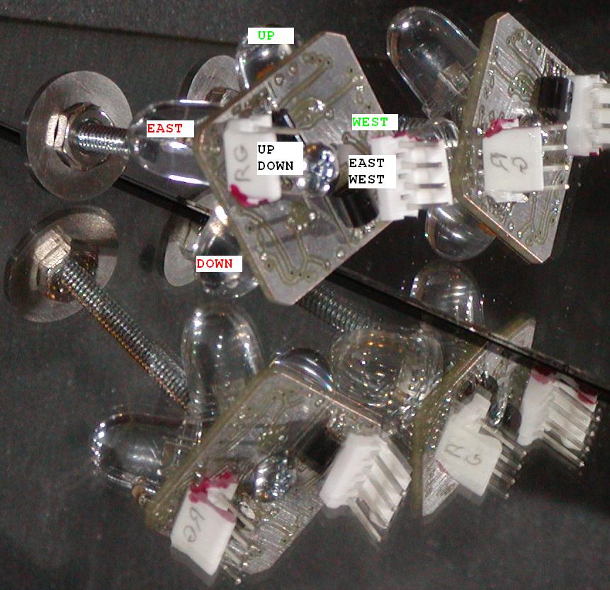
Click the image.
Dual Axis Sensor with Parking on Both Axes.
1. Single axis
Parking or no-parking.
2. Dual axis
Parking or no-parking on either axis.
Note! The grounds on the power units main power inputs must be connected together.
"R" corresponds to the the Red indication on the power unit which is moving toward the Parking or Reverse direction.
"G" corresponds to the the Green indication on the power unit which is moving in the Forward direction.
ReMote sensor Mounting
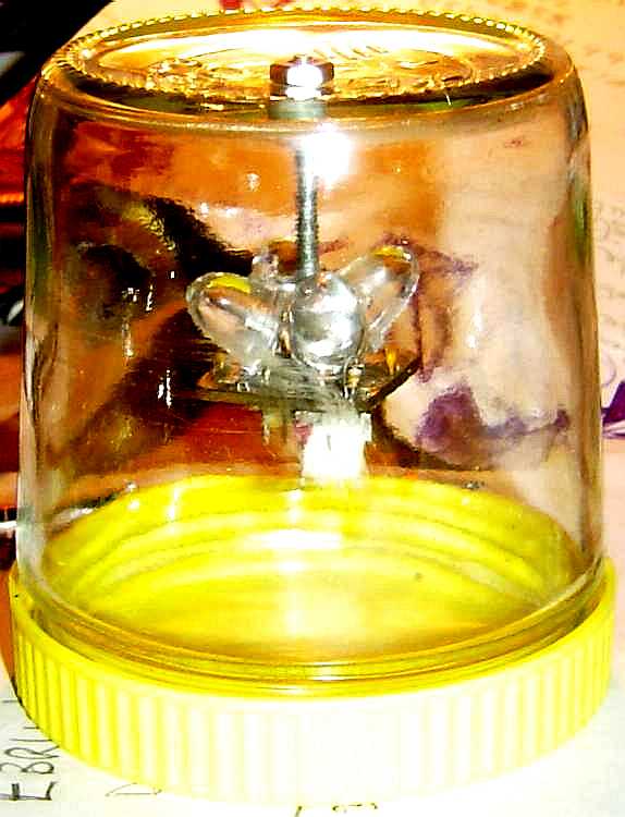
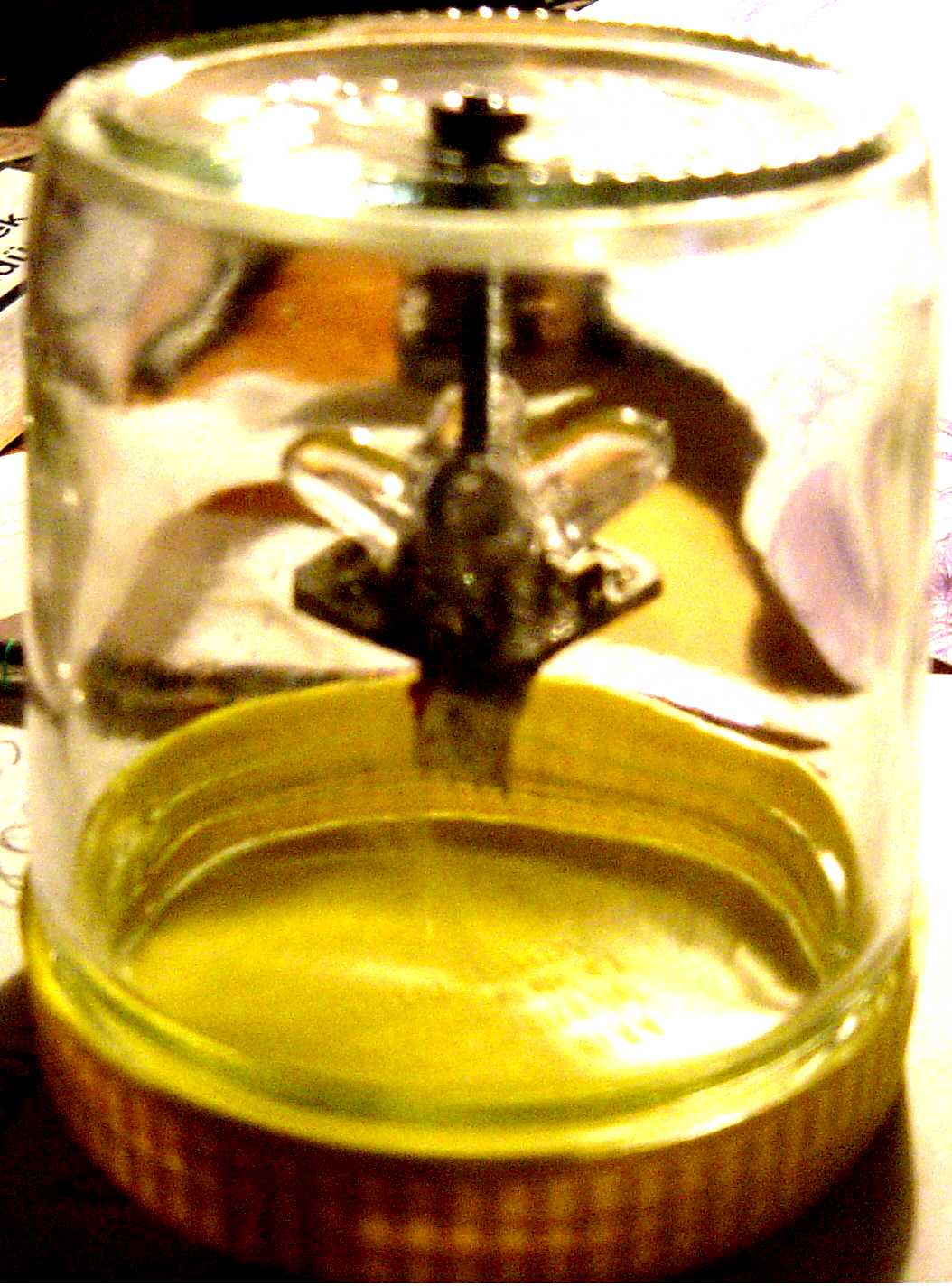
Federico Constante, of Turkey, mounted his Dual Axis ReMote sensor in a glass jar. He drilled a hole in the jar bottom.
ReMote sensor Schematic
dualremotesensor
 DualRemoteSensor
 DualRemoteSensorPP
 DualRemoteSensorNN
Note! This schematic serves a dual purpose. It's a diagram of the the full LEDDRM ReMote sensor PC board including all the features such as parking and no-parking. If cut in half it forms two single LEDSRM ReMote sensors.
LEDDRM Connection Diagram
External Control of the Power Unit
LED3XS24 "c" Schematic
The Power Unit, PU, portion of an LED3X tracker with a ReMote sensor is named the LEDSRM24Vc3PPack. This is essentially the LED3X tracker with the LED sensors replaced with a connector. Of course this can't be called a "Tracker" anymore without its sensor so I simply call it a "Power Unit" or PU.
A 180KΩ resistor must be connected between CONN2-pin2 and CONN2-pin3 just as in the Parking form of the ReMote sensor schematic
1. Leaving CONN2-pin2 and CONN2-pin3 open will cause the PU to drive the motor Reverse or to the Red direction. This is also the "Parking" direction.
2. Connecting CONN2-pin3 to CONN2-pin4 will cause the PU to stop moving the motor.
3. Connecting CONN2-pin2 to CONN2-pin4 will cause the PU to drive the motor Forward or to the Green direction.
<redrok@redrok.com>