Last modified on 20141204
actuator
Linear Actuators
pro
Pro Brand International, Inc.
oem@pbigroup.com | Marietta, Ga |
| |
| Specification: |
| MODEL |
HEAVY |
REGULAR |
MINI |
Stroke Length |
18"/24"/36" |
12"/18"/24" |
6"/8"/10"/12" |
Suggested Dish
Size |
2.4M~4.8M |
1.2M~3.6M |
60cm~1.5M |
Static Load |
3000lbs |
1000lbs |
500lbs |
Dynamic Load |
1200lbs |
550lbs |
300lbs |
Speed(Rated Load) |
5.2mm/sec |
5.6mm/sec |
6.2mm/sec |
Resolution(Reed) |
32Pulse/inch |
48Pulse/inch |
76Pulse/inch |
Resolution(Optical) |
83Pulse/inch |
125Pulse/inch |
203Pulse/inch |
Resolution(Pot) |
10 turns, 10K ohm |
10turns, 10k Ohm |
---------- |
Input Voltage |
36 VDC |
36 VDC |
36 VDC |
|
|
|
| Model Designation: |
|
| Example: HARL3618+ |
H |
SuperJack
Regular Modeli (Q: Heavy; H: Regular; D: Mini) |
A |
Actuator (A: Acme; B: Ball) |
R |
Reed
Sensor. (R: Reed; O: optical; B: w/o sensor) |
L |
Limit
switches equipped |
36 |
DC
36V motor (30, 24V motor available) |
18 |
Stroke
length (12,18 and 24 inch standard / other stoke length is available upon request.) (6, 8, 10, and 52 inch reported) |
+ |
Advanced |
|
|
j&d
| |
Pro Brand HARL3018 18" $ 69.95 Acme
Pro Brand ZARL3018 18" $129.00 Acme Large tube
Pro Brand QARL3024 24" $139.00 Acme
Pro Brand VBRL3024 24" $169.95 Ball
Pro Brand, SuperJack, Eagle Aspin specifications
Saginaw 24" $199.00 Acme
Saginaw 24" $229.00 Ball
Von Weise 18" $109.00 Acme
Von Weise 24" $159.00 Acme
|
saginaw
Danaher Motion
Literature Request | | Performance Pak Actuators (PPA)
|
venture
Venture
(937)233-6832 Sales
(800) 500-9275
Martin Mershad Special Products
Pace Electronics
(612)542-9620
626 Mendelssohn Ave N
Minneapolis, MN
55427-4306 | Dayton, Ohio |
Venture Maxi Industrial Series 3000/1500 Lb -48" Ball
Tube
Diam |
Limit/
Clutch |
Gearbox |
Screw
Type |
Sensor |
6" Inc |
1" Inc |
Tube
Mount |
End |
| 8 |
1 |
C |
5 |
1 |
3 |
0 |
1 |
1 |
8 2.0"
7 1.5" |
0 Non
1 LS
2 Clch
3 Both |
1 / 58 19
12 A F
24 B G
36 C H
90 D J
110 E K |
5 Ball
- Acme |
0 None
1 Reed
2 Hall
3 Pot |
1 6
2 12
3 18
6 36
8 48 |
0 0
1 1
2 2
3 3
4 4
5 5 |
1 Trunnion
2 In-line
3 Clamp
4 HDClamp |
1 1/2Flt
2 1/2Sw
3 3/4Sw |
Venture Maxi Ball 3000/1500 Lb -40"
Venture Gold Plus 24" Ball
Venture Gold Plus 18" Ball
Venture Maxi 8500 1000/ 250 52" Acme
Venture Maxi 8500 1000/ 250 36" Acme
Venture Maxi 8500 1000/ 250 24" Acme
Venture Maxi 8500 1000/ 250 18" Acme
Venture Mini Blackjack 7600 18" Acme
Venture Micro Skylighter 7500 18" Acme
|
skyvision
Skyvision
(800) 543-3025
(800) 500-9275 | ? |
Venture Ultra Power 1500 Lb 24" $279.95 Ball W Boot
Venture Ultra Powered 36" $319.95 Ball W Boot
Venture Super Power 24" $149.95 Acme
Venture Super Power 36" $229.95 Acme
Venture Super Power 52" $249.95 Acme
Venture Action Packed 18" $169.95 Ball
Venture Action Packed 24" $169.95 Ball
Venture Valueline-18" $ 89.95 Acme
|
ranger
Ranger;s Online Satellite Store
mportus@budget.net | OR |
Von Weise 18" $ 99
SuperJack(Pro Brand) 18" $ 79
Venture Super Duty 24" $139
|
internet
| |
Von Weise 18" $ 89.95
Von Weise 18" $104.95 W Boot
Von Weise 24" $134.95
Von Weise 24" $149.95 W Boot
SuperJack(Pro Brand) 600Lb 18" $ 68.95
SuperJack(Pro Brand) 600Lb 18" $ 83.95 W Boot
SuperJack(Pro Brand) 900Lb 18" $ 86.50
SuperJack(Pro Brand) 900Lb 18" $101.50 W Boot
SuperJack(Pro Brand) 1200Lb 24" $109.95 Acme
SuperJack(Pro Brand) 1200Lb 24" $124.95 Acme W Boot
SuperJack(Pro Brand) 1500Lb 24" $139.50 Ball VBRL 3024
SuperJack(Pro Brand) 1500Lb 24" $154.50 Ball VBRL 3024 W Boot
Venture Maxi 18" $ 97.95
Venture Maxi 24" $101.95
Venture Maxi 36" $169.95
Venture Gold Plus 18" $109.95 Ball
|
satshop
SatShop
| Germany | Superjack
|
telsat
Telsat� Communications Ltd
+64-6-356-2749
telsat@intec.gen.nz | New Zealand |
Von Weise 800 lbs 18" $90.00 US$ FOB Factory
Von Weise 800 lbs 24" $98.00 US$ FOB Factory
Saginaw Thompson 36" $230.00 US$ FOB Factory
|
worm
Worm Drive
An interesting method of making a worm drive is to use a flexible threaded rod turning against a gear.
Since the threaded rod is flexible many more "teeth" make contact with the "gear" than if the threaded rod were strait or stiff.
Mine was made with 8-32 brass threaded rod.
The torque imparted is surprisingly strong.
The gear has teeth formed by repeatedly running or pressing the threads into its surface.
For wooden gears a rubber or wooden mallet is used to pound the threaded rod into the disk.
For plastic gears a bit of heat on the threaded rod will melt it into the edge of the disk.
Or as an alternative one can cut a grove into a threaded rod to act as a cutter.
For example:
Using a disk of plywood 24 inches in diameter and 8-32 threaded rod which has 32 threads per inch.
PI * 12" * 32/" = 2412/1 gear ratio. That's a high gear ratio.
Make sure your motor bearings can take the axial load. Not all motors can handle this load. One might need a separate axial load bearing
This idea was obtained from an issue of Sky & Telescope for use as a polar right ascension drive.
l2r
Linear to Rotary motion.
An method to convert the linear motion of a linear actuator to rotary motion.
actuatormath
Linear to Rotary Mathematical Concepts.
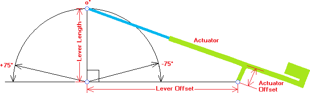
Diagram to show the mathematical concepts.
window
Flexible Gear Linear Actuator
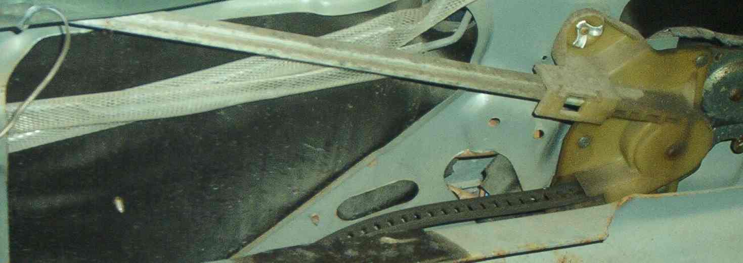
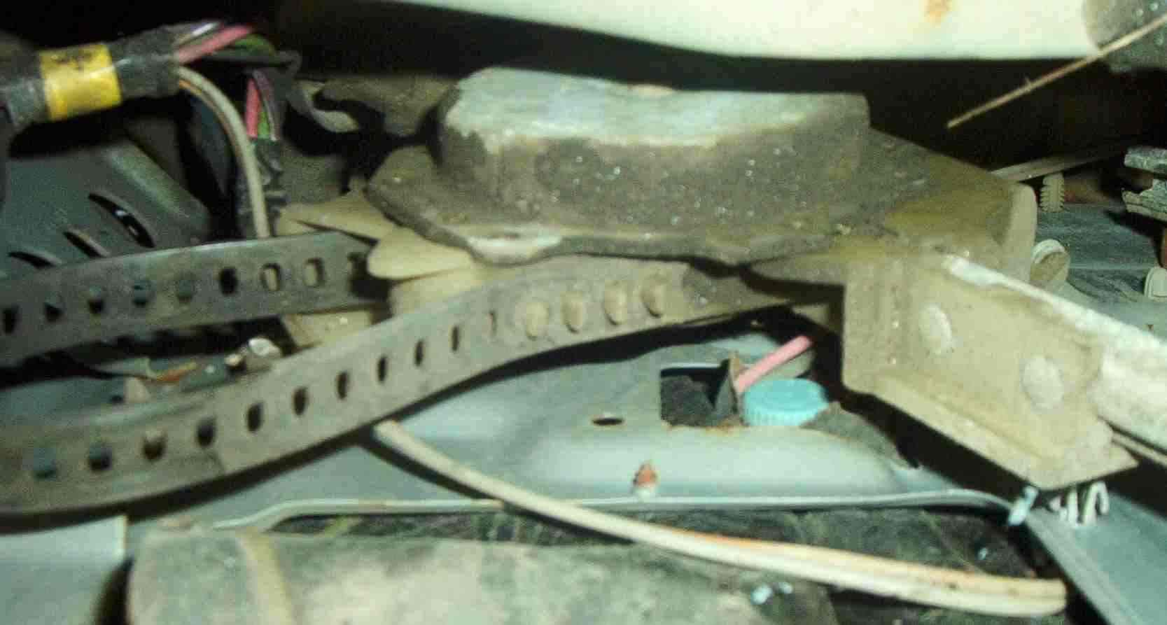
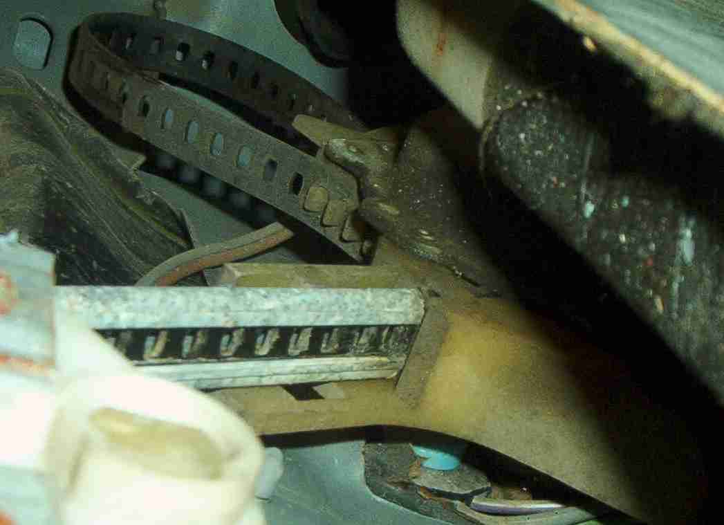
Virgil Vinz found this interesting window actuator from a Pontiac 6000.
The actuator is a flexible plastic strip riding in a steel track. The strip is punched with holes that fit over a motorized sprocket. Think of this as a mutant sized 35mm film sprocket. Neat Huh!
ACT01
act01
Proposed but untested, well somewhat tested now, SCR/MOSFET H-Bridge.
act023p
SCR/MOSFET H-Bridge three �
act021p
SCR/MOSFET H-Bridge single �
heliostats
Heliostats
ledhelo1
The next two trackers are based on the ultra low power "Beam" technology pioneered by Mark W. Tilden.
This controller is essentially 2 pairs of LED sensors in an H-bridge configuration. One H-bridge pair is for up/down motion and the other for east/west motion. This configuration has completely independent motions.
A feature of this controller is the ultra low power consumed during idle time. It's probably around 10uA or so. The voltage monitor circuit shuts down the drive and lets a low power source such as a small PV panel charge the energy storage capacitors. When sufficient voltage is detected the energy stored in the capacitors is dumped to the H-bridge circuits. Quite high currents are provided to the motors making motion is short bursts.
ledhelo2
3Ø LED Heliostat Drive I am currently working on.
This controller is essentially 3 pairs of LED sensors in a 3Ø-bridge configuration. The driver is capable of operating 3 actuators. The motors are connected in a Delta configuration. The apexes of the delta are connected to the center connection of each half-bridge. Of course only 2 actuators are required as the third is stationary and fixed.
When a pair of LEDs turns on the associated top SCR the bottom SCRs of the other half bridges is turned on and movement of the shadow mask is toward this LED.
In the absence of any turn on conditions all SCRs are off and no movement results.
If 2 or more LED turn on conditions occur multiple SCRs in both the top and bottom will fire. In many circuits this would be a disastrous condition, however, in this circuit the only thing that happens is there is no movement and the storage capacitor is discharged. Actually this condition won't happen in normal circumstances when the light is bright.
The LED sensors are arranged in a circle of 6 with a shadow mask sized to exactly illuminate each LED 50%. They are connected in pairs at opposite sides of the circle.
US4342501
Solomen US4342501 Radiant energy collector with focal point between the plane of the frame and earth
Note, there is a U-joint at the base of the reflector.
US4930493
Sallis US4930493 Multi-lever rim-drive heliostat
Note, there is a U-joint at the base of the reflector.
US5945961
Price US5945961 Satellite Dish Mount.
Note, there is a U-joint at the base of the reflector.
US4251819
Vickland US4251819 Satellite Dish Mount.
Note, there is a Ball-joint at the bottom of the reflector instead of a U-joint. Tipping of the reflector is resisted by the cross brace. A disadvantage is the motions are quit complex. OK, the U-joint has complex motion too but not as complex as the Ball-joint mount.
US4798949
Wilcox US4798949 Linear actuated optical concentrator
Note, the specific detail of using a universal joint where the lower, rigid arm attaches to the mirror. This U-joint prevents tipping of the mirror left or right. The two linear actuators provide tilt and rotation to the mirror.
US3945015
Gueguen US3945015 Satellite Dish Mount.
Note, there is a U-joint at the center of the reflector.
3phtam
 3Ø Tamiya model. (Hey, it looks kind of like a little robot!)
A picture is worth way more than a thousand words. As US4798949 and US3945015 teaches us that a U-joint keeps the mirror from tipping I have a rigidly mounted U-joint at the top. The other U-joints could be ball joints if one can find ball joints that can take high angles.
US4798949 needs the other 4 U-joints because of the use of linear actuators. These generally require that the near and far ends be prevented from rotating. The U-joint solved this problem for him. But technically, only the single lower U-joint prevents the mirror from turning.
Note, US4342501, US4930493, US5945961, and US3945015 only use 1 U-joint.
I worked out a method where I can eliminate the need for limit switches in the actuator.
If a crank is used the motion can't run into the end and jam as in a linear actuator.
The protection limit switches can be eliminated. My model uses a Tamiya Twin-motor gear box model 70097. The crank mechanism can be scaled to large sizes with no foreseeable problems.
Q. What if the controller gets confused and runs over the end and the crank moves to the upper part of the motion?
A. Nothing bad happens. The controller just continues to move the crank in the same direction, (the control action is reversed), until the crank is back on bottom and normal control is resumed.
If course, there is nothing wrong with using limit switches.
In this type of mount pairs of actuators are generally operated:
1. For up/down motion the motors are driven in the same direction.
2. For East/West motion the motors are driven in the opposite directions.
tamiya
 The model heliostat drive uses hobby gear boxes by Tamiya.
 Model 70097
And another with good specifications.
Model 70097
And another with good specifications.
como
MFA/Como Drills
Ondrives Ltd.
thermostat
Thermostat for Solar Cooker
ledcook
DCB asked an interesting question. He was wondering if I could add a temperature control feature to the LED3 solar tracker. He wants to use the tracker to run a solar cooker.
He said that with a dish concentrator the temperature in the oven can get to high. He suggested an input to the tracker could move it off axis to control the temperature.
I have bread boarded a couple of circuits to try this. I also will try a thermostat version. However, the thermostat seemed kind of high in cost compared to the electronic version. Especially when settings of 350F are needed for baking.
One could get carried away with this with oven timers and such.
Thermocouples could be used here but they require OpAmps and cooking gust doesn't require that precise of a temperature accuracy.
I will look at positive temperature coefficient sensors such as platinum or copper types.
If a sensor resistance of about 1KOhm were used these could be more rugged than the diode sensors.
Each of these circuits is connected to the LED3 5V regulator. The 2 diodes on the left are connected across R2 & R3. Essentially the circuit grounds the LED sensor pairs fooling the tracker into heading for home or park position.
The lower diode is the temperature sensor. It probably should have a glass case to take the temperature. OK, I know 350F is way above the normal operating temperature of semiconductors, but it works in this case. You will need to mount the sensor inside the oven and make connections with high temperature wire. I have some 30 gauge twisted pair wire wrap wire that has Kynar, (?sp), insulation. I twisted and crimped this to the diode to make a good mechanical connection. I also added solder. The solder may melt but still makes a good electrical contact.
Other diodes may be used such as the emitter base junction of a power transistor.
The choice of components is not critical at all. The resistor values have been chosen to allow operation to about 350F.
small
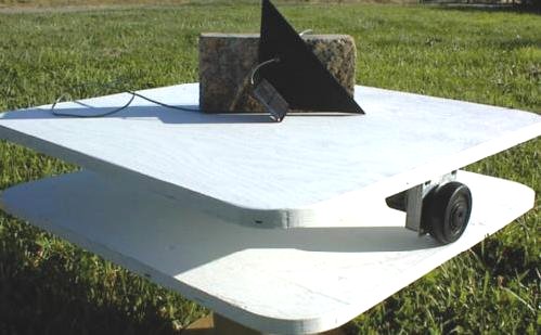
"Small Power System" Tracker for Solar Cookers
Small Power System Tracker
The Solar Cooking Archive.
They have a neat solar cooker tracker described and sold by:
Small Power System
This is clearly the simplest possible solar tracker. Basically 3 parts.
1. A motor, a gearmotor with a fairly high gear ratio, either in the motor gearbox or external. I like total gear ratios of 100,000/1 or more would be nice. In the Small Power System version this has a rubber tired wheel which is able to turn the base of the cooker. In this example the motor is mounted on the West side.
2. A small solar panel, one capable of running the motor. This is mounted on the West side of the cooker close to the back and bottom corner and aimed toward the sun.
3. A shadow blocker. Generally made of metal, wood, or cardboard is also mounted on the West side between the PV panel and the Sun. Arrange it so a shadow can move across the panel.
This one operates as a kind of Lazy Susan. When its aimed a bit to the East of the Sun sunlight passes the shadow blocker and hits the PV panel. The power generated moves the motor to the West until a shadow starts to cross the PV panel and the motor stops movement. This system is pretty accurate, better than 10° or so, well within the aiming tolerance for box cookers. The accuracy is dependent on the clarity of the sky. If the sky is clear more power is generated causing the tracker to move further West than if the sky is overcast.
The motor in the picture looks very much like a
Grainger's 2L003 gearmotor with 7000/1 gear ratio with a wheel on the output shaft. I'm guessing here, the wheel is about 3" in diameter and running around a circle of 36" in diameter for a gear ratio of 12/1. And a total gear ratio of:
7000/1 * 12/1 = 84000/1. Close enough!!!
This should run fairly slowly yet have ample force to do the job and fast enough to easily keep up with the Sun.
Note, usually solar cooker trackers only track in 1 direction, usually to the West. The cook will reset or move the cooker to the East when loading the unit.
ledcooker
Small Simple Solar Trackers for Solar Cookers
LED Cooker1 & LED Cooker2 Solar Trackers
This is about the simplest electronic solar tracker with good tracking accuracy one can make. It's based on a pair of LEDs connected in the same way as my normal trackers. The accuracy is generally better than 1°. Great for concentrating types of solar cookers such as parabolic dishes and troughs.
Since this is for a cooker one can assume that a person will be present to manually move the cooker to the Eastern position. This tracker only moves in one direction, to the west. OK, it may turn all the way around and be setup for the morning.
Power comes from a small solar panel. Match the solar panel to the motor. It only needs to be large enough to run the motor. Or a small battery can also be used.
I designed ledcooker1 more than 10 years ago. Since BLUE silicon nitride LEDs are now available, at reasonably low cost, I just made ledcooker2. Since BLUE produces more voltage this version has less parts and looks better with the 3 LEDs, RED GREEN BLUE, inline with each other.
The IRLZ44N power MOSFET has quite a low gate threshold voltage. This, along with running in low current analog mode, allows operation of these tracker designs with the low voltages developed by the LED sensor circuits.
I like the Grainger's 2L003 for this design. I made one of these using a small toy car as the motor set under one side of the cooker with the wheels doing the turning.
There are many sources for small high gear ratio motors on the Internet. See:
Jameco 6, 12 & 24VDC Reversible Gear Head Motors
My Notes Text FileNote, usually solar cooker trackers only track in 1 direction, usually to the West. The cook will reset or move the cooker to the East when loading the unit.
diftemp
Differential Temperature Sensors
Differential Temperature Sensors
I've posted a couple of differential temperature sensor circuits. These are preliminary and should be used as the starting point for more in depth circuits that control output power.
instrumentation
Solar instrumentation
pv-i2v
PV current to voltage converter.
This circuit, when used with a small single PV cell, will do a good job of measuring the solar influx after calibration.
It's based on the primary property that the short circuit current of a PV cell closely matches the incident insolation.
tilden
Tilden
Tilden H-Bridge
http://www. ????
by Mark W. Tilden
This is a very neat design. Well worth studying how it works.
robots
Solar Robots
BEAM Solar Engine
http://nis-www.lanl.gov/robot/html/plans.html
by Mark W. Tilden
Micro Power Solar Engine
http://www.xs4all.nl/~sbolt/e-lezersbijdrage.html
by Ken (K.G.A.) Huntington
Alf
http://wollongong.apana.org.au/~ben/alf/schematic.html
by Ben Hitchcock
A solar powered Alfa Romeo Matchbox car.
Fred
http://wollongong.apana.org.au/~ben/fred/schematic.html
by Ben Hitchcock
A little robot that searches for light.
D2 Robotics
http://www.panunzio.demon.co.uk/circuits.htm
by David & Dean
Many tiny robots.
Dave
http://www.geocities.com/SoHo/Lofts/1121/beam/dave.htm
by Justin Fisher
Tiny photovore.
Solarbotics Ltd.
http://www.solarbotics.com/
Skitterbot
http://www.working-ideas-co.com/
Skitterbot.
Cheap PV cells.
Forever Flasher
http://www.tripoint.org/kevtris/flasher.html
Kevin Horton
suntrek
Suntrek
http://www.suntrekenergy.com/
Small solar panels.
pagermotors
PagerMotors.com
http://www.pagermotors.com/
Small solar panels and pager motors.
trackers
Other Solar Trackers
cdsrely1
This is a non electronic analog tracker. It's very simple using only two relays and two Cadmium Sulfide, CdS, photoresistive cells.
The relay is from Radio Shack 275-249A. The coil is rated at 12VDC and 200 ohms.
The CdS cell has a full sunlight resistance of 50 to 75 ohms. This resistance is a little low for reliably dropping out of the relay when in shadow. I adjust the resistance by using a Sanford Sharpie Permanent marker. If you get too much marker on it can be removed with fingernail polish remover or acetone.
This tracker is not as accurate as the electronic ones. It's perfect for flat panels thermal or PV panels.
ledshex2
This is a greatly improved version of the LED sensor circuits with Schmitt Trigger Logic and MOSFET power drivers. This circuit fits onto a .7"x1.4" circuit board. The MOSFET drivers are capable of delivering about 10A to the motor load. They can do this because the power on duty cycle is about 10%.
tunneldiode
Tunnel Diodes
http://www.panunzio.demon.co.uk/circuits.htm
Excerpt from the GE Transistor Manual on Tunnel diodes.
 3Ø Tamiya model. (Hey, it looks kind of like a little robot!)
 Model 70097