
I had intended to start the manufacturing of 10 full heliostat array systems for sale to the public beginning the summer of 1997 but I ran into a snag. I investigated the cost of shipping the all metal frame, which was very large and quite heavy. I determined that it was too expensive. I had shipping cost estimates of about $1000us to a customer in California. Of course the shipping cost would be less for customers in Minnesota as I could trailer the equipment myself. This cost seemed unreasonable to me. I suppose there are discount shippers that could undercut the normal rates. I was determined to reduce the shipping costs.
My solution was to redesign the frame in such a way that it could be constructed from locally obtained materials by the customer as a kit. The kit will consist of a bill of materials and prints so one can use a portable drill, saw and hand tools to construct and assemble the frame. The 10 mirror assemblies will be shipped in a special wooden crate. This wooden crate has provision for all special hardware, actuators, and computer interfaces.
The customer is expected to supply an IBM type PC for control of the system. The basic requirement for this computer is that it have a printer port and be running any version of DOS. The printer port is connected to a special interface connector. This connector interfaces between the printer port and RJ-12 type 6 wire flat telephone wire. Power to run the interface comes from the printer port itself. If the customers computer printer port can't supply enough power an external power supply can be used. The computer can be located as much as 1000 ft. from the heliostat array, maybe even more but I haven't tried it yet.
The heliostat array actuators are powered by a 13.8 volt lead acid deep cycle trolling motor battery. This battery is charged using a conventional charger. If conventional AC mains are not available a small PV solar panel and temperature compensated shunt regulator can be employed. I have a Solarex M-55 panel and Solarex shunt regulator on the prototype system. This battery system powers an old Compaq 8086 laptop computer used as the heliostat controller.
In addition the battery system also powers a Kenwood 7930 30 watt 2 meter amateur radio transceiver and a Peet Brothers Ultimeter 2000 weather monitor. This equipment is a component of an experimental Sky Warn severe weather monitoring and reporting system. Amateur radio equipment is used to collect basic real time data and present it to the US Weather Bureau.
I have used an MVS, Merrimack Valley Systems, single board 8088, actually a V20 chip, computer as the controller. This computer is a very low power unit, less than .10 watt. It has the controller program stored in EPROM. This computer starts up running the control program. I experimented with this computer mainly to learn if there would be a need for a special controller. I have determined that it would be too expensive to sell this computer to my customers. The expense is not just the cost of the computer itself but the additional expense of FCC EMI compliance testing. If my customer purchases this computer himself I can install the control program in it for him.
All of my interface boards and drivers have no internal clocks. Furthermore the customers PC, used as the controller, should have FCC class B EMI compliance. This combination doesn't require any compliance testing. I believe this combination is also exempt from the European, Canadian, or Japanese EMI requirements.
Last Spring, 1997, David Wells challenged many of us on the Internet alt.solar news groups to get our rears in gear and actually build commercial solar concentrators. Some of the projects centered about several technologies:
| 1. | Dish type thermal concentrators. |
| 2. | Dish type Photo voltaic concentrators. |
| 3. | Trough type thermal concentrators. |
| 4. | Heliostat type thermal concentrators. |
| 5. | Heliostat type photo voltaic concentrators. |
I will describe some of my impressions of each of these technologies and attempt to be impartial about the pros and cons. Of course I will be comparing this equipment from the stand point of an intimate knowledge of my heliostat arrays. I can't help but be somewhat biased toward heliostats. In the 28 years that I have studied and experimented with alternative energy I have tried a lot of things and learned a lot of practical lessons.
Thermal concentrators of all types are relatively easy to build when compared to PV concentrators. Whatever the technology used the concentrator reflectors perform well even if relatively inaccurate. This characteristic is not a disadvantage in thermal types because the concentrated area need not be particularly evenly illuminated. This tends to make the reflector cheaper to build.
Conversely, all photo voltaic concentrator applications require very accurate reflectors. PVs intrinsically have a special problem when used in concentrator systems. The problem is related to the DC impedance of each cell relative to the amount of illumination. Essentially the impedance is inversely proportional to the solar influx. Another characteristic of PV cells is that they have a reverse breakdown of from -4 to -7 volts. Usually many cells are strung in series to obtain high voltages. The problem occurs when any one cell is shadowed by as little as 10% from the others in the string. This shadowing increases the impedance of this cell.
Relative impedance example.
K
=
Constant associated with cell size.
L
=
Solar illumination in Lamberts.
Ic
=
K * L Fully illuminated cell current.
Rc
=
Vc / Ic Fully illuminated cell impedance.
Is
=
Ic * ( 100% - 10% ) Shadowed cell current.
Rs
=
Vc / Is Shadowed cell impedance.
In this example the impedance is about 10% higher than the normal cell impedance.
By definition the current in a string, since they are all in series, is the same through all cells. Since the impedance of the weak cell is about 10% higher than the rest it is not strong enough to generate the same current as the rest of the cells in the string. Consequently this cell drops and even reverses voltage until breakdown occurs and the current flow equals the series current determined by the strong cells.
Breakdown is very destructive in several ways:
| 1. | The weak cell is now not converting sunlight into electricity. This means that all of the inputted light is converted into heat as opposed to only 85% as in a normal cell. The cell gets hotter than the other cells. Of course the impedance goes up with increases in temperature and a consequent runaway increase in power dissipation. |
| 2. | The weak cell may dissipate several times the power of the strong cells because the current is flowing across a cell with from -4 to -7 volts instead of through a cell with +.55 volts. This implies that the power dissipated in the weak cell is about 10 times more than the normal cell. |
| 3. | The power dissipated in a cell that is in reverse breakdown is most likely to be in a localized zone. This localized heating may contribute to the destruction of the cell in a few milliseconds. |
There is evidence that a bird flying close to the PV cell receivers would be enough to destroy some cells unless some form of protection were employed.
OK, It isn't all that bad. Since the cells have a reverse breakdown minimum of -4 volts and good cells have a forward generation voltage of about +.55 volts it takes about 4 strong cells to overcome 1 weak cell. This is a total of 5 cells. One solution is to put a reverse connected protection diode across some of the cells. Since the protection diode has a forward voltage drop of about .8 volts it could be connected across N number of cells for full protection.
komp
 "Practical Photovoltaics"
 Get the book here.
| Vbd | = | -4 Cell breakdown voltage. |
| Vb | = | .8 Diode forward voltage drop. |
| Vc | = | .55 Cell generating voltage. |
| nstring | = | int((-Vbd -Vd)/ Vc) |
| nstring | = | int((- -4 -.8)/.55) |
| nstring | = | int( 5.818 ) |
| nstring | = | 5 Cells in the string. |
This implies that there needs to be a protection diode rated at the full rated cell current for every 5 cells. Of course if the breakdown voltage is higher then the protection diode can span more cells.
Another minor problem is that all cells in this group are not generating power even though only one cell is shadowed.
Schematic of protection diodes used in conventional 1x PV panels.
(Use Courier New font)           Series Schottky Leakage
                                 Current Protection Diodes
                             \ | (Blocking Diodes)
         +-----------+-------->|--------
         | +         |C      / |        +
1/2 of -----       -----
12V PV  ---          ^   Shunt
Panel  -----        /|\  Silicon
or 6V   ---         A|   Protection
Panel    |           |   Diode
         +-----------+
         | +         |C
1/2 of -----       ----- Shunt
12V PV  ---          ^   Silicon
Panel  -----        /|\  Protection
or 6V   ---         A|   Diode
Panel    |           |
         +-----------+
         | +         |C
1/2 of -----       -----
12V PV  ---          ^   Shunt
Panel  -----        /|\  Silicon
or 6V   ---         A|   Protection
Panel    |           |   Diode
         +-----------+
         | +         |C
1/2 of -----       ----- Shunt
12V PV  ---          ^   Silicon
Panel  -----        /|\  Protection
or 6V   ---         A|   Diode
Panel    |           |                    -
         +-----------+--------------------
Prudent design suggests the Shunt protection diodes need to be sized to handle the maximum current that your panel can deliver. The diode is usually installed inside the junction box on the back of the panel. This box can get very hot. Good practice suggests that the diodes used in this application be derated 2 to 1. For a 3A panel one should use a 6A diode. These diodes can be standard silicon rectifier types.
blockingdiode
An Electronic Blocking Diode
This circuit uses a Quad 2 input CMOS NAND Schmitt trigger gate:
CD4093
The oscillator is a simple relaxation type made with gate U1A. R2 and C1 define the frequency of the oscillator at around 60KHz.
The Cadmium Sulfide Photo-Resistive Cell is low in resistance when light hits it and pulls the input to gate U1B high. This enables the signal to drive capacitor C2. This AC voltage is limited to +12V and -.6V around zener diode D2 which is attached to the source of the power MOSFET.
When present, this AC voltage transfers charge through diode D3 to the gate of the MOSFET and turning it ON strongly. The IRFZ48 MOSFET has a very low ON resistance of 10 mOhms. At 10 amps this is a voltage drop of only .1V. With an IRF3703 the voltage drop would be only .028V. Cool huh!
When the the AC voltage is not present, as when it's dark, the charge on the gate is dissipated through resistor R5 turning the MOSFET OFF. However, the intrinsic body diode can still conduct from the PV panel to the battery. It also prevents loss of stored charge in the battery due to leakage in the panels.
bridge(Use Courier New font) Series Schottky Leakage
Current Protection Diodes
\ | (Blocking Diodes)
+--------------+------->|--------
| + / \+ / | +
1/2 of ----- \ / \C/
12V PV --- ---\C /---
Panel ----- A /|\ /|\
or 6V --- / | |A\
Panel | / \AC
+-------+-------------+
| + AC\ /
1/2 of ----- \C/ \ /
12V PV --- /--- ---\C
Panel ----- /|\ A /|\
or 6V --- |A\ / |
Panel | \ /-
+--------------+
| + / \+
1/2 of ----- \ / \C/
12V PV --- ---\C /---
Panel ----- A /|\ /|\
or 6V --- / | |A\
Panel | / \AC
+-------+-------------+
| + AC\ /
1/2 of ----- \C/ \ /
12V PV --- /--- ---\C
Panel ----- /|\ A /|\
or 6V --- |A\ / |
Panel | \ /- -
+--------------+-----------------
An interesting variation is to use a 4 diode bridge rectifier. Connect the 2 AC terminals together. Since the two diodes are in parallel and thermally connected together the current rating is effectively double the bridge rating. Many bridge rectifiers have provision for a heat sink.
The Series protection diode prevents self discharge of the battery during the night.
Note that the series protection diode may be included in the shunt regulator. I have several shunt regulator circuits that all have this diode here:
http://www.redrok.com/electron.htm#charger
We have discussed another method of power conversion that has a possibility of higher conversion efficiency in the presence of weakly illuminated cells and still not cause breakdown. Lets say we breakup the string into several sets of cells. Each set has a DC to DC current to high voltage converter. This arrangement doesn't require a protection diode. For a converter of this type more cells can be in each set for a given protection.
Cell protection using DC-DC converters.
nconv
=
int(- Vbd / Vc)
Vbd
=
-4 Cell breakdown voltage.
Vc
=
.55 Cell generating voltage.
nconv
=
int(- -4 /.55)
nconv
=
int( 7.272 )
nconv
=
7 Cells in the converter.
Each converter up converts the cell current to about 300VDC. 300VDC is ideal because there are numerous vendors of 300VDC to any other DC output voltage or even sine wave AC outputs.
Solar photovoltaic cells can have many different efficiencies depending on many different conditions. This web site has the legitimate records.
 Photovoltaics Special Research Center
Another testing lab with more recent data.
WELCOME to the TISO Center
TISO: Testing Center for photovoltaic components
Completed Tests - Power measurement
My heliostat arrays are optimized for a nominal concentration factor of about 10 to 1. Of course multiple sets of arrays can be added together for more concentration factors. The PV cells are best used at concentration factors of 50 to 1 or as much as 400 to 1 as in the Midway Labs concentrators.
fresnel
 I have an example of a simple tracker here.
Concentrators can be used to produce thermal power.
Dishes that are used with PV cells or heat engines will produce thermal power as a byproduct. This lower grade power can be used to heat water for domestic use.
Dish concentrators, with their relatively expensive construction methods, appear more cost effective when in hybrid conversion systems.
One of the best advantages of a dish concentrator is the very high temperatures that can be obtained. These have the possibility of melting aluminum or maybe even hotter.
One big disadvantage of dishes or troughs is the remote location of the receiver. The receiver is required to be constructed a s part of the reflector assembly. Also the receiver of a dish is high in the air and not in a convenient location near the ground.
Heliostats used in thermal applications deliver the concentrated power to a location that is more convenient. This location can be several hundred feet from the mirrors. This location can even be on the north side of a building in a location not normally considered to be "solar". The power can be delivered to one of several receivers at will.
Thermal power can be used for many tasks.
| 1. | Basic thermal storage at high temperatures. |
| 2. | Process heat such as melting aluminum. |
| 3. | Heat engines such as Stirling or Rankine engines. |
Basic heat storage at high temperatures is very efficient in volume usage compared to conventional low temperature thermal storage. The heat can be stored more efficiently because of the smaller heat loss surface areas. Insulation may be even better than when a vacuum is used. Heliostats excel in this application because the receiver and heat storage can be integral and on ground level.
Process heat can be anything from water heating to higher temperature drying of materials such as crops. Matching each application to the right type of concentrator is a challenge. In general dishes are required when high temperatures are needed. Heliostats are generally best suited where temperatures up to 600°F to 800°F are needed.
Stirling engines are the purview of dishes running at 50 to 1 or higher.
Rankine engine steam generators work well with both dish and heliostat concentrators. International Solar Collectors is a good example of reasonable cost trough collectors using refrigeration gases in Rankine engines.
The real challenge in utilizing Rankine engines is in the expander. Conventional piston steam engines are very expensive. One is $2,900 us and 5 hp. This seams way to expensive to me.
On a suggestion from David Wells, he and I have been thinking of using a refrigeration scroll compressor as a Rankine expander. David is using an automotive air conditioning compressor from Sanden / Sankyo. I am trying to use a Copeland scroll compressor with integral induction motor. If this path to the implement of Rankine engine technology is fruitful then low cost solar engines are to come. Good luck Dave.
The steam generator is the easiest part. The best boiler, IMHO, should be a flash tube type made by casting a coil of stainless steel tubing in a slab of aluminum.
Basically the higher the temperature the absorber gets the more robust the horizontal stagnant air insulator becomes.
I have used it at temperatures of up to 600°F.
This is a diagram of the secondary mirror used to reflect the normally reflected horizontal light upwards into a vertical direction and upward into the horizontal air insulated receiver.
                      UP
                 ==============
      Insulation ==============
                 ===Receiver===
                 ===  Air   ===
                 === ^ ^ ^  ===
 North               | | |  === South
        -------------- |>/  ===
 \ | /               | |/   ===
- Sun - -------------->/ Mirror set at
 / | \               |/ about a 45° angle.
        ------------>/      ===
                      Down
The mirror doesn't have to be flat. If it is curved some amount of concentration can be obtained with a consequent reduction in the size of the receiver. With a smaller receiver there will be less heat lost through the normal insulation and also less lost due to radiation from the open side.
coverThe horizontal stagnant air layer insulator has the potential of having much higher insulation factors than the vertical glass insulators normally used.
Another advantage of using secondary mirrors in the receiver is the cost. Basically mirrors are made of 1 layer of glass or even aluminized Mylar. This stuff is much less expensive then the cost of 2 layers of high temperature glass normally used in vertical insulated receivers.
SMF1100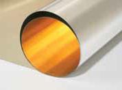 * 3M SMF1100 <http://www.taindustrial.net/renewable-energy-market/3m-solar-mirror-film-1100-1/>
 Nielsen Enterprises <http://www.mirrorsheeting.com/>
 Some data on the polyester film.
reflectech
Some data on the polyester film.
reflectech ReflecTech Solar Films
 Discount Hydroponics
 Granite Hydroponics
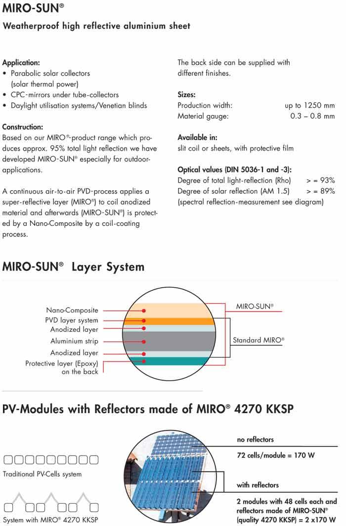 Alanod Miro-Sun
 Rosco
Rosco Sunspot
This is not a price quote. I am only speculating on possible sales prices. My law guy won't let me quote prices yet. I expect to sell our heliostats system at around $20us/ft² of mirror in sizes of around 200ft². Also about $0.40us per installed thermal watt based on 10KW solar thermal output. This then equates to about $4000 per heliostat array. You supply the computer and materials for the frame and I supply almost everything else including the hardware less the installation.
For comparison a rule of thumb for PV panels is that they cost about $40us/ft². They then have an installed cost of about $4us per watt not counting the mounts. Of course this is for non tracking panels. Also the wasted thermal power is not recoverable.
There is plenty enough power to flash water into steam. I'm working on a Rankine engine to electric power receiver now. I won't be selling this but I do like to learn about the technology. This could be as much as 20% efficient. If the engine costs $2000us and receiver costs $4000us the total system would now be $6000us. This predicts that electricity would have an installation cost of $3us per watt electric. This system would deliver 1KW of electricity all day and the 9KW thermal waste heat can be stored for domestic hot water.
We can custom make almost any size and any concentration factor you might need. Multiple arrays can work in tandem to multiply the amount of power at a single receiver. Only one computer is needed to run many array units.
One basic requirement is that there be a parallel or printer port. This port drives the bit serial interface to the mirror actuators.
I have been using an obsolete Pocket PC from Zeos in the prototype. I also used an 8088 based Compaq laptop. I am also using a tiny HP 95/100/200 palmtop. The application simply doesn't require a high speed computer. It does need to have a computer that can use a compiler that uses double precision floating point arithmetic for the solar position calculations. The 8 bit process controllers can't do this. (OK, I suppose they can, it's just that I find it more useful to program in a language that works in my normal PC.) Even though the calculations are extensive they don't have to be done very often.
The software is the heart of the whole system. Software keep the time. Software calculates the position of the sun. Software calculates the required orientation of the mirror. Software controls the position of the mirror at night or when high winds could cause damage. Software compensates for mechanical errors in the hardware. Software does everything.
The modern lowest cost solution to most complex mechanical systems is software running in a computer that controls simple hardware devices. Gone are the days of pre cut cams and complex linkages in favor of programmable cams and programmable virtual linkages which cost nothing to change except the time to load a new program.
Solar heliostats come in two basic types that I call "T Pole" and "Hinge". The control software operates differently for each type.
polarMy software compensates for almost every mechanical error I can conceive of. Some of these errors are the specific orientation of the bearings and the angles between the bearings. Other errors compensated for are non-linearities in the mechanical linkages.
Once I had written the code to orient a heliostat it was easy to remove some of the transformations to control both single and dual axis conventional collectors. Of course these collectors have all their mechanical errors compensated for also.
 Calculations related to the relative positions of the sun and the earth.
 Calculations from the Odeillo Solar Furnace (sorry it's in French).
The basic engineering design requirements are based on a wind loading of 10lb./ft² from any direction. The minimum safety factor is 8. This makes for a very sturdy and stiff design.
Really low cost manually operated heliostat arrays for the third world are in the works. If the locals build everything and have a village elder doing the aiming I think the cost could be as low as $2us/ft² in a 100ft² size. With 9KW peak thermal output it would be easy to do solar cooking and baking. It can also power water desalination and sterilization units.

