
Heliostats have a potential of being the truly lowest cost solution to all the power one needs. These systems can provide for domestic heating, electricity, and lighting.
The realization that all flat plate solar collectors have lots of expensive collector area and still deliver only low grade temperatures compelled me to look for a better solution.
Many years ago I noticed that cheap glass mirror tiles cost less than $1.00/ft² ($.59 at the time). Flat plate collectors generally need two layers of transparent insulation that each cost more than $2.00/ft². Flat plate collectors also need a layer of insulation on the back side. Flat plate collectors usually are not optimally oriented to the sun.
Lets see; can I think of a system that uses lots of cheap mirrors and a small expensive collector?
"AHA! A heliostat."
You may consider that all the light from the sun is parallel, because it is so far away. Each mirror is initially adjusted so they each reflects light onto the same spot. When the sun moves in any direction all mirrors are adjusted by exactly the same amount to track the sun and they still reflect light onto the same spot. This is mathematically exact and works anywhere in the world when reflecting on any spot. This also works with any arbitrary arrangement of mirrors. (I won't discuss the proof here just trust me for now.)
I have been thinking about these concepts since 1972. The germ of the idea occurred during one of the energy crisis. I was thinking about tracking thermal collectors then the "AHA!"thought popped into my head. The thought that mirrors are much cheaper than flat plate collectors was very powerful. The secondary thought the actual collector can be stationary and on the ground was a plus.
Hey, this ain't so hard.
Heliostats are mirrors that track the sun and reflect the sunlight onto a central receiving point. Most heliostat solar power systems consist of arrays of heliostats.
If the mirrors are inexpensive enough then they can collect solar power at a cost that is less expensive and with higher efficiency than flat plate collectors. The arrays of heliostats concentrate the power on a relatively small collection point that, though more expensive per ft² than flat plate collectors, are smaller and thus the total cost is lower.
If used for the collection of heat the temperatures can be quite high, over 600°F. If used to generate electricity the cost of the precious solar cells are only a fraction of the cost of cells in flat plate systems.
Note! As of 980306 I have abandoned the idea of using PV cells in concentrator heliostat applications. There are some subtle problems with the cells that I don't know how to overcome. See:
up980301.htm#pv
The heliostats I am describing consist of many small elements. Each of these elements is an individual heliostat. When directed to a common collection point there will be a concentration proportional to the number of elements used. If you use a 200ft² array of 10 elements the concentration factor will be about 10 to 1. With this much concentration factor the relative thermal collection efficiency is about double that of a tracking flat plate collector. If compared to stationary flat plate collectors the relative collection efficiency may be about 4 times better.
I have coined a term, (I think?), called the "Stasis Temperature". This is the temperature a system will attain with no power extracted from the system.
The plane of the collector is normal to the sun at noon on January 8th. This is approximately the day that the earth is closest to the sun. I have chosen winter as the standard time as this is when homes need the most solar power. The day must be very clear and generally with no wind or in a sheltered area such as a south facing open garage. I have done this measurement in Minnesota. I assume that the temperature would be higher in lower latitudes as the distance traveled through the atmosphere is shorter when the sun is at a higher altitude. (Others have suggested that I do this measurement at the spring or fall equinoxes as this would be a better average throughout the year. I will stick with the January 8th day because it will give me a worst case reading. Besides, winter is the time of the year that heat is needed most)
I have chosen this model as it represents the most general type of collector on the market. Other models can be devised for other purposes. Others may have higher or lower stasis temperatures depending mainly on the quality of the absorber, the transparent insulation R value, or time of year.
Triple air layer insulation is used in higher temperature flat plate collectors where the added insulation value allows higher stasis efficiency and temperatures. If higher useful temperatures are required then the lowered efficiency is acceptable.
When used in the heliostat system the triple air layer insulation may not be the technology to use when used below 600°F as there would be less total output power available. Remember the heat loss is proportional to the collector area. In heliostat systems the collector is only a fraction of the area of a flat plate collector. Single air layer insulation may be best below 300°F. No insulation may be needed below 170°F.
cover
Another concern with high temperature operation is the temperature attained by the intermediate glass layers. Since clear glass has a very low thermal emissivity the intermediate glass layers may absorb enough heat to cause melting. The heat loss in the glass, though small in percentage, can cause the glass to become very hot. The fiber glass "Kalwall" type of insulation does not work as it deteriorates at high temperatures and high flux of ultraviolet light. (Recently I have seen some examples of water cooled windows that may fix this problem.) I think this is what you are looking for.
All materials have absorption and emissivity factors. Absorption refers to the ability of a material to absorb radiation. Emissivity refers to the ability of a material to emit radiation.
In physics, absorption factors refer to the full spectrum of radiation. We in the solar field are referring to absorption over a specific spectral range of sunlight here on earth. The absorption factor is referenced to a true black body surface which by definition is 1. The radiation that is not absorbed is lost due to reflection.
Emissivity usually refers to the radiation of power from a surface at a certain temperature. The emissivity factor is referenced to a true black body surface which by definition is 1.0. The published emissivity factors, I think, are measured at a temperature of 25°C. The radiated power is normally greater at higher temperatures.
Most solar collectors are operated at elevated temperatures well above that which was used to measure the emissivity factor. The result is that the amount of emitted radiation is higher than expected.
Classically flat black paint, Parsons black, was used on solar collectors. While it is cheap to apply it is not necessarily the best material to use. The black paint has an absorption factor of .98. This means that 98% of the available solar power is converted into heat in the collector. The collector gets hot. Some of the heat is emitted as radiation. In this case 98% of the possible black body power is radiated.
Look at it this way. If the emissivity factor is lower we get to keep more of our hard earned power. Ideally the emissivity should be zero. Of course that's impossible. The best we can do is to look for materials that have high absorption and low emissivity.
This is a table of absorption and emissivity for some solar materials. (?)
(I don't have the citation but it was a good one.)
There is another table from:
Department of Agricultural Engineering, University of Missouri-Columbia. (U of Miss)
A good reference on Radiant-Heat Transfer. (Marks (1))
Marks Standard Handbook for Mechanical Engineers ninth edition
Eugene A. Avallone & Theodore Baumeister III
Page 4-66 to 4-70
Here is an article about a game changing metamaterial. It effectively reflects a high percentage of incoming sunlight during the day and radiates 110W/m^2 at night and 90W/m^2 during the day.
"New engineered material can cool roofs, structures with zero energy consumption."
"New material keeping structures chilled out this summer."
"New engineered material can cool roofs, structures with zero energy consumption."
"Cost-effective passive cooling."
University of Colorado at Boulder
"Engineers have developed a scalable manufactured metamaterial -- an engineered material with extraordinary properties not found in nature -- to act as a kind of air conditioning system for structures. It has the ability to cool objects even under direct sunlight with zero energy and water consumption."
| * Solec Selective Surface Coatings and Paints. |

| * Solchrome Systems India Limited Selective Surface Coatings. |

| * The Fridge Architectural Science Lab Dr. Andrew Marsh solar absorption and normal emittance for a range of surface finishes. |
| * The Fridge At the WayBack Machine internet archive. |
Absorptivity & Emissivity table 1 plus others.
| aS | E | ||||
|---|---|---|---|---|---|
| Solar | Surface | aS/E | |||
| Material | Absorption | Emissivity | ratio | Comments | Reference |
| Silver, Highly polished | 0.02 - 0.03 | 3.00 | Marks (1) | ||
| Gold, Highly polished | 0.02 - 0.04 | 3.00 | Marks (1) | ||
| Barium Sulfate with Polyvinyl Alcohol | 0.06 | 0.88 | .07 | The Fridge | |
| Aluminum polished | 0.09 | 0.03 | 3.00 | ? | |
| Magnesium Oxide Paint | 0.09 | 0.90 | .10 | The Fridge | |
| Magnesium/Aluminum Oxide Paint | 0.09 | 0.92 | .10 | The Fridge | |
| Aluminum quartz over coated | 0.11 | 0.37 | .30 | ? | |
| Aluminum, Highly polished | 0.04 - 0.06 | 3.00 | Marks (1) | ||
| Snow, Fine particles fresh | 0.13 | 0.82 | .16 | ? | |
| Zinc Orthotitanate with Potassium Silicate | 0.13 | 0.92 | .14 | The Fridge | |
| Aluminum anodized | 0.14 | 0.84 | .17 | ? | |
| Aluminum foil | 0.15 | 0.05 | 3.00 | Aluminum foil gets very hot because of this high ratio. | ? |
| Potassium Fluorotitanate White Paint | 0.15 | 0.88 | .17 | The Fridge | |
| Zinc Oxide with Sodium Silicate | 0.15 | 0.92 | .16 | The Fridge | |
| Paint, White zinc oxide | 0.16 | 0.93 | .17 | ? | |
| GSFC White Paint NS-74 | 0.17 | 0.92 | .18 | The Fridge | |
| Titanium Oxide White Paint with Potassium Silicate | 0.17 | 0.92 | .18 | The Fridge | |
| Zerlauts Z-93 White Paint | 0.17 | 0.92 | .18 | The Fridge | |
| Chromium | 0.08 - 0.26 | 3.00 | Marks (1) | ||
| Dow Corning White Paint DC-007 | 0.19 | 0.88 | .22 | The Fridge | |
| GSFC White Paint NS43-C | 0.20 | 0.92 | .22 | The Fridge | |
| Titanium Oxide White Paint with Methyl Silicone | 0.20 | 0.90 | .22 | The Fridge | |
| Zerlauts S-13G White Paint | 0.20 | 0.90 | .22 | The Fridge | |
| Light colored paints, firebrick, clay, glass | 0.04 - 0.40 | 0.90 | .24 | U of Miss | |
| Biphenyl-White Solid | 0.23 | 0.86 | .27 | The Fridge | |
| P764-1A White Paint | 0.23 | 0.92 | .25 | The Fridge | |
| Zirconium Oxide with650 Glass Resin | 0.23 | 0.88 | .26 | The Fridge | |
| Solec LO/MIT selective surface paint | 0.21 - 0.26 | 0.15 - 0.19 | 1.38 | LO/MIT I/II products are low emissivity, non thickness dependent coatings. | Solec |
| Catalac White Paint | 0.24 | 0.90 | .27 | The Fridge | |
| Hughson White Paint Z-202 | 0.25 | 0.87 | .29 | The Fridge | |
| Hughson White Paint Z-255 | 0.25 | 0.89 | .28 | The Fridge | |
| Hughson White Paint Z-255 | 0.25 | 0.89 | .28 | The Fridge | |
| 3M-401 White Paint | 0.25 | 0.91 | .27 | ? | |
| Hughson White Paint A-276 | 0.26 | 0.88 | .30 | The Fridge | |
| Hughson White Paint V-200 | 0.26 | 0.89 | .29 | The Fridge | |
| OSO-H White Paint 63W | 0.27 | 0.83 | .33 | The Fridge | |
| Opal Glass | 0.28 | 0.87 | .32 | The Fridge | |
| Sherwin Williams White Paint (A8W11) | 0.28 | 0.87 | .32 | The Fridge | |
| Mautz White House Paint | 0.30 | 0.90 | .33 | The Fridge | |
| Snow, Ice granules | 0.33 | 0.89 | .37 | ? | |
| GSFC White Paint NS44-B | 0.34 | 0.91 | .18 | The Fridge | |
| Sperex White Paint | 0.34 | 0.85 | .40 | The Fridge | |
| Dupont Lucite Acrylic Lacquer | 0.35 | 0.90 | .39 | The Fridge | |
| GSFC White Paint NS-37 | 0.36 | 0.91 | .40 | The Fridge | |
| Sherwin Williams F8WJ2030 w Polasol V6V241 | 0.36 | 0.87 | .41 | The Fridge | |
| Sherwin Williams White Paint (F8WJ2030) | 0.39 | 0.82 | .48 | The Fridge | |
| Tedlar White Paint | 0.39 | 0.87 | .45 | The Fridge | |
| Hughson White Paint Z-202+1000 | 0.40 | 0.87 | .46 | The Fridge | |
| Aluminum paint (bright) | 0.30 - 0.50 | 0.40 - 0.60 | .80 | U of Miss | |
| Hughson White Paint A-276+1O36 | 0.44 | 0.88 | .50 | The Fridge | |
| Dull brass, copper, galv. steel, aluminum | 0.40 - 0.65 | 0.20 - 0.30 | 2.10 | U of Miss | |
| Colored paints, brick, light brick, | 0.50 - 0.70 | 0.85 - 0.95 | .67 | U of Miss | |
| Concrete | 0.60 | 0.88 | .68 | ? | |
| Galvanized metal new | 0.65 | 0.13 | 5.00 | ? | |
| Brick, red (Purdue) | 0.65 | 0.93 | .68 | ? | |
| Concrete and stone, dark | 0.65 - 0.80 | 0.85 - 0.95 | .81 | U of Miss | |
| Galvanized metal weathered | 0.80 | 0.28 | 2.90 | ? | |
| Metal, plated Black chrome | 0.87 | 0.09 | 9.70 | ? | |
| Anodize Black | 0.88 | 0.88 | 1.00 | The Fridge | |
| Martin Black Velvet Paint | 0.91 | 0.94 | .97 | The Fridge | |
| Solec Solkote selective surface paint | 0.88 - 0.94 | 0.28 - 0.49 | 2.36 | SOLKOTE HI/SORB-II is an optical coating specifically formulated for solar thermal applications. | Solec |
| Metal, plated Nickel oxide | 0.92 | 0.08 | 11.00 | This is stainless steel heated until the nickel oxidizes. | ? |
| Metal, plated Black sulfide | 0.92 | 0.10 | 9.20 | ? | |
| Pyramil Black on Beryllium Copper | 0.92 | 0.72 | 1.28 | The Fridge | |
| Metal, plated Cobalt oxide | 0.93 | 0.30 | 3.10 | ? | |
| Polyethylene Black Plastic | 0.94 | 0.92 | 1.01 | The Fridge | |
| Martin Black Paint N-150-1 | 0.94 | 0.94 | 1.00 | The Fridge | |
| Tedlar Black Plastic | 0.94 | 0.90 | 1.04 | The Fridge | |
| Iron and Steel, strongly oxidized | 0.95 | 3.00 | Marks (1) | ||
| Hughson Black Paint L-300 | 0.95 | 0.84 | 1.13 | The Fridge | |
| Paladin Black Lacquer | 0.95 | 0.75 | 1.27 | The Fridge | |
| Black Crystal | 0.92 - 0.98 | 0.08 - 0.25 | 5.76 | Thermafin's Black Crystal Selective Surface Coating (apparently replaced with "Crystal Clear"). | Thermafin |
| Crystal Clear | 0.95 - 0.97 | 0.09 - 0.14 | 8.35 | Thermafin's Crystal Clear Selective Surface Coating. | Thermafin |
| Carbon Black Paint NS-7 | 0.96 | 0.88 | 1.09 | The Fridge | |
| Carbon Black Paint | 0.96 | 0.88 | 1.09 | The Fridge | |
| Chemglaze Black Paint Z3O6 | 0.96 | 0.91 | 1.05 | The Fridge | |
| Delrin Black Plastic | 0.96 | 0.87 | 1.10 | The Fridge | |
| GSFC Black Silicate MS-94 | 0.96 | 0.89 | 1.08 | The Fridge | |
| GSFC Black Paint 313-1 | 0.96 | 0.86 | 1.12 | The Fridge | |
| Hughson Black Paint H322 | 0.96 | 0.86 | 1.12 | The Fridge | |
| Velesat Black Plastic | 0.96 | 0.85 | 1.13 | The Fridge | |
| Solchrome | 0.94 - 0.98 | 0.10 - 0.14 | 8.00 | Solchrome Systems India Limited. | Solchrome |
| Ebanol C Black | 0.97 | 0.73 | 1.33 | The Fridge | |
| Ebanol C Black-384 ESH* UV | 0.97 | 0.75 | 1.29 | The Fridge | |
| 3M Black Velvet Paint | 0.97 | 0.91 | 1.07 | The Fridge | |
| Parsons Black Paint | 0.98 | 0.91 | 1.08 | The Fridge | |
| Flat black paint | 0.97 - 0.99 | 0.97 - 0.99 | 1.00 | U of Miss | |
| Paint, Black (Parsons) | 0.98 | 0.98 | 1.00 | I understand this is lamp black mixed with spar varnish. | ? |
Selective surfaces | |||||
| Solec LO/MIT selective surface paint | 0.21 - 0.26 | 0.15 - 0.19 | 1.38 | LO/MIT I/II products are low emissivity, non thickness dependent coatings. | Solec |
| White paint | 0.23 - 0.49 | U of Miss | |||
| Solec SOLKOTE selective surface paint | 0.88 - 0.94 | 0.28 - 0.49 | 2.36 | SOLKOTE HI/SORB-II is an optical coating specifically formulated for solar thermal applications. | Solec |
| Copper, aluminum, or nickel plate with CuO coating | 0.08 - 0.93 | 0.09 - 0.21 | 3.37 | U of Miss | |
| Black Crystal | 0.92 - 0.98 | 0.08 - 0.25 | 5.76 | Thermafin's Black Crystal Selective Surface Coating (apparently replaced with "Crystal Clear"). | Thermafin |
| Copper treated with NaCIO2 and NaOH | 0.87 | 0.13 | 6.69 | U of Miss | |
| Solchrome | 0.94 - 0.98 | 0.10 - 0.14 | 8.00 | Solchrome Systems India Limited. | Solchrome |
| Crystal Clear | 0.95 - 0.97 | 0.09 - 0.14 | 8.35 | Thermafin's Crystal Clear Selective Surface Coating. | Thermafin |
| Metal, plated Black sulfide | 0.92 | 0.10 | 9.20 | ? | |
| Metal, plated Black chrome | 0.87 | 0.09 | 9.70 | ? | |
| Metal, plated Nickel oxide | 0.92 | 0.08 | 11.00 | This is stainless steel heated until the nickel oxidizes. | ? |
Links to sites that have Absorptivity or Emissivity data:
thermalconnectionSierra Pacific
Infrared cameras and night vision equipment.
Heriot-Watt University, Department of Physics
Black-body radiation, The Planck function.

| * Sandia National Labs, Sun Lab, Environmentally Friendly Solar-Selective Absorber Material is the Result of Laboratory-Industry Collaboration. Thermafin uses Black Crystal coatings. |
This is a table of reflectivity and emissivity for some building materials. (Marks (2))
Marks Standard Handbook for Mechanical Engineers ninth edition
Eugene A. Avallone & Theodore Baumeister III
Page 12-85, Table 12.4.21b
Nielsen Enterprises
They sell reflective Mylar films.
Hydroponic Gardening/REFLECTIVE FILMS
3019 S 256th St.
Kent, WA. 98032
(253) 941-7281
Reflectivity and Emissivity table 2.
| % | E | ||
|---|---|---|---|
| Average | |||
| Surface | Reflectivity | Emissivity | Reference |
| Aluminum foil, bright | 92 - 97 | 0.05 | Marks (2) |
| Reflective Mylar Film | 90 - 93 | 0.05 | Nielsen |
| Aluminum sheet | 80 - 95 | 0.12 | Marks (2) |
| 1/8" Plate glass mirrors coated with aluminum on back | 85 | ||
| Aluminum-coated paper, polished | 75 - 84 | 0.20 | Marks (2) |
| Steel, galvanized, bright | 70 - 80 | 0.25 | Marks (2) |
| Rhodium | 70 - 80 | ||
| Stainless Steel | 62 - 65 | ||
| Chromium | 60 - 63 | ||
| Aluminum paint | 30 - 70 | 0.50 | Marks (2) |
| Building materials: wood, paper, glass, masonry, nonmetallic paints | 5 - 15 | 0.90 | Marks (2) |
A useful reflection measurement can be made by comparing the reflection from a sample to a reference surface.
I use 1/8" thick bathroom mirror tiles which have a reflectivity of about 85%. Arranging 2 mirrors the reflectivity is about 72% and 3 mirrors is about 61%.
Another is good quality reflective Mylar, which uses aluminum as the reflective surface at >95%.
A very nice reference light source is the open sky near the zenith, (strait up), on a cloudless day.
Place these side by side and look back through the mirrors at the sky. It is quite easy to compare the brightness. The less reflective surface appears darker than the more reflective one.
The sample doesn't have to be flat, it can be curved as in a concentrator. Or even wrinkled. It doesn't matter as the sky, over a reasonably small area, say 15 degrees, is even in brightness.
Stasis temperature is simply the temperature that the standard model, or other model, collector reaches compared with the ambient temperature. Stasis efficiency is proportional to the inverse of the actual collector temperature rise divided by the potential temperature rise with no power extracted from the collector. When any collector temperature is the same as the ambient temperatures then this is the maximum solar heat flow out of the system. This is the 100% stasis efficiency temperature, (although the temperature is so low as to make it not useful). It stands to reason that at higher temperatures there will be less heat available for transfer to a load as the remainder of the heat is lost through radiation or conducted through the insulation. At some higher temperature, the stasis temperature, there will be no heat available for transfer and all is lost to radiation or conducted through the insulation. This is the 0% stasis efficiency temperature, (although the available heat is so low as to make it not useful for power generation). This temperature may be useful for such tasks as baking or firing ceramics.
I have derived the equation myself from actual measurements that I have made. If I have made an error, such as using dirty glass, have extra unaccounted heat losses, have air leaks, or have un-calibrated thermocouples I will only be off in the stasis temperature value. This error, even if in error by 25%, would not significantly alter the conclusions gained from knowing that concentrator solar collectors nearly always have higher efficiencies than flat plate collectors of any type.
The stasis temperature measurement is based on a standard model called the "Stasis Model". The stasis model is a flat plate collector with a black body type of absorber under 2 layers of borosilicate glass with a spacing of 1/2 inch and spaced 1/2 inch from the absorber. Thus there are two 1/2 inch air spaces in front of the absorber. This is double air layer insulation. There is also 6 inches of polyisocyanurate foam insulation on the back. A thermocouple is attached to the absorber for measuring the stasis temperature and another outside in the air for measuring the ambient temperature.
This equation is not rigorous as it is only the first order linear approximation of the true stasis efficiency equation. I have not needed to find the nonlinear equations yet as this one has served me well when comparing different collector types at relatively low temperatures.
 /     / (Tc - Ta)      \ \
| 1 - | ---------------- | | * 100 = ST%
 \     \ (Ts - Ta) * CF / /

ST% = Stasis efficiency of a particular theoretical solar collector system.
Tc  = Collector temperature as measured in a particular collector system.
Ta  = Ambient air temperature around the collector in °F.
Ts  = Stasis temperature. I use (Ts - Ta) of 340°F. You could use 188°C.
CF  = Solar Concentration Factor.
Stasis temperature can be converted from °F to °C at will. Stasis efficiency is dimensionless as it's a percentage.
I have found that a flat plate collector normal to the sun with 2 layers of glass and perfect insulation will have a differential temperature rise of about 340°F. If you extract enough heat from the system so that the temperature rise is 170°F then the system is 50% efficient theoretically.
When sun light is concentrated the stasis temperature rise is multiplied by the concentration factor. In my example of 10 to 1 the stasis temperature rise would be 3400°F theoretically. (Of course there are other losses not described here which limits this temperature.) If the extraction temperature is 340°F above the ambient then the system would be about 90% efficient. This has the effect of reducing the required area by about half for the same heat extraction compared to a flat plate collector.
Of course the flat plate collector could never reach the temperatures obtained by the concentrator. They don't even try.
A similar explanation can be had on page 312-317 of:
 Get the book here.
[SOLAR] Understanding Performance Equations of Solar Collectors
(A message from David Wells to the Solar Concentration Mailing List.)
Thermomax ( http://209.116.252.72/effi.htm ) gives the efficiency of their
collector as:
Efficiency of Collector = 0.84 - 2.02 (Tm-Ta)/G - 0.0046G[(Tm-Ta)/G]**2
Where:
Tm=Mean working temperature of fluid, Celsius
Ta=Ambient air temperature
G=Solar Irradiance in W/m²
This sort of equation is typical of all types of solar thermal collectors. There are some interesting aspects of it worth mentioning.
First, notice that the first term, 0.84, is what you would get for the efficiency if Tm were set equal to Ta. This would be the equivalent of running LOTS of ambient temperature fluid through the collector. In this case, the thermal losses would be equal to zero. Thus, the efficiency of the collector would depend entirely on how transmissive the optics are, and how absorptive the absorber is. For this reason, this test condition measures the "optical efficiency" of the collector.
So, the first term, which is independent of any thermal or irradiance effects, is called the "optical efficiency" of the collector. For the Thermomax collector, the equation says the optical efficiency is 0.84.
Now look at the second term. The second factor is 2.02. This factor multiplies the temperature difference term divided by the solar irradiance term, (Tm-Ta)/G.
So, in my last memo, when I mentioned my "rule of thumb" as being 1/4% reduction in efficiency per degree increase in working temperature, or per PERCENT insolation, it is this second term that is determining this effect (mostly--although the third term has a minor influence, too).
For example: say the solar irradiance is 1000 W/m². The second term becomes 2.02/1000(Ta-Tm). If (Ta-Tm) is 100 °C, then the efficiency is found from the optical efficiency, 0.84, minus this second term, 2.02 x (100/1000), giving about 0.44. The drop in efficiency from the optical efficiency was about 20%, or stated another way, about 0.2% per °C. Close to the "Dave 1/4% rule", right?
Now the third term.
0.0046G[(Tm-Ta)/G]**2 is a small "non-linear" correction term. By "non-linear", we mean that it is a term that accounts for the small amount of bow in the efficiency curve. This bow is due in part to the loss terms which don't go as the first power of the temperature or irradiance. For example, we've seen that the infra red loss goes as the fourth power of the absolute temperature (Stefan-Boltzman law). That's the largest effect which contributes to this term. There are other effects, such as convection effects, all of which are non-linear, and contribute slightly to the bow of the curve (the non-linearity of the curve).
For our example, at solar irradiance of 1000 W/m² and temperature difference of 100 °C, this term becomes:
0.0046 x 1000 x (100)^2 = 0.046. Rounding, this is about 0.05. That's 5% per 100°C, or 0.05 per °C.
So, to get the full "first-order" or linear term, plus "second-order" or non-linear term, you add 0.2 plus 0.05 to get---drum roll, please!--0.25 percent efficiency drop per °C OR per percent insolation drop. That's the origin of the "quarter percent rule of thumb".
-David Wells
This is the minor little correction part which has to get added to the equation.
Thanks Dave!
What could be more simple!
thermomax Thermomax has some efficiency graphs.
I assume that stasis efficiency is linear from 0% to 100% between stasis temperature and ambient temperature. I think this is reasonably valid at temperatures below 300°F. Stasis efficiency, if taken rigorously, is certainly not linear with high temperatures. I have not needed to calculate stasis efficiencies at temperatures more than 600°F yet.
The stasis efficiency is only the starting point for total efficiency calculations. It describes the theoretical maximum efficiency at a particular temperature that a collector can attain. This is an efficiency goal that cannot be exceeded.
Other efficiencies to be considered are:
| 1. | Mirror light Reflection efficiency | MR%=90% Dirty mirrors. |
| 2. | Mirror Cosine angle efficiency | MC%=90% Mirrors set at an angle to the light rays. |
| 3. | Mirror Scattering efficiency | MS%=98% The mirrors are not flat. |
| 4. | Solar Light Divergent efficiency | LD%=96% Generally light from the sun diverges 1/2°. If the light is sent a long distance then the concentration factor is reduced as the spot the mirror reflects upon will be larger than the size of the mirror. |
| 5. | Atmospheric Scattering efficiency | AS%=96% Flat plate collectors are pretty good with overcast clouds. The heliostat is not very bad at collecting scattered light. |
| 6. | Receiver Reflection efficiency | RR%=95% Light reflected from the receiver. |
| 7. | Receiver Cosine angle efficiency | RC%=95% Receiver set at an angle to the incident rays. |
| 8. | Receiver Absorption efficiency | RA%=95% Light absorbed by transparent insulation in the receiver. |
| 9. | Non black body radiation absorption efficiency | BB%=150% This can be greater than 100% as selective absorption coatings that absorb short and long wave radiation differently. |
| 10. | Thermal losses in Insulation | (TI%=95% Heat loss through insulation in receiver). |
| 11. | Solar Cell efficiency | (SC%=15% Light to electric conversion losses). |
These efficiencies must all be multiplied together along with the stasis efficiency at a particular temperature to get the final total efficiency. Multiply solar influx by the total efficiency.
The rule of thumb for tracked flat plate collectors is about:
1000Watt/m², 900Watt/yd², or 100Watt/ft²
The rule of thumb for concentrators is about:
800Watt/m², 700Watt/yd², or 80Watt/ft²
Tot%= ST%* MR%* MC%* MS%* LD%* AS%* RR%* RC%* RA%* BB%* TI%
Tot%= 95%* 90%* 90%* 98%* 96%* 96%* 95%* 95%* 98%* 130%* 95%
Power out thermal  = 61 Watts / ft² = 80 * 76%

Power out electric =  9 Watts / ft² = 80 * 76% * 15%
You may think that the heliostats are expensive to make. DOE's Solar I and Solar II, the solar power towers at Barstow California, and others are very expensive systems. They don't have to be low in cost as they were powered not by the sun but by "Government Dollars". For any system to be truly cost effective they need to deliver power at a cost that is less than that delivered by the local energy utilities.In my area this is $.06/KWhour. Another rule of thumb is the installed cost of the system needs to be less than about $1.00/Watt. None of the many systems I have studied come close to this performance.
In Minnesota there is a law that requires that "solar collectors" have a stand alone pay back period of less than 40 years in today's dollars. Those small tracking concentrating trough water heaters that produce about $80 of hot water per year are not permitted to be called "solar collectors" in Minnesota. Without government tax incentive money and research grants none of the systems I have studied can be called "solar collectors" in Minnesota if installed near a utility power source. The power obtained from the utilities is just too cheap to compete effectively. If a system can produce power at a low enough cost it should be able to stand alone in the marketplace and compete with the utilities on an even playing field.
The heliostats that I have been working on are very low in cost. They are constructed of low cost materials and use no high tech construction methods. I think they are about $5.00/ft² but this is only a guess at this time. The use of a personal computer to compute the orientation of the mirrors is the only high tech component. This computer performs high precision calculations that compensate for all of the mechanical construction errors. El Cheapo 8088 XT class computers are fast enough to compute the orientation math for at least 20 individual heliostats arrays. (I have been using an obsolete Zeos Pocket computer as the controller.)
Note! Gangs of heliostats are linked together in such a way that they are controlled by a pair of calculation. Theoretically, if all heliostats are constructed to close mechanical tolerances such that they all move synchronously only a few calculation are made for them all. As a practical matter smaller sets of arrays are linked. Each set should have its own calculations as there may be orientation errors when widely spaced. All errors are accounted for in my software.
In my prototype I have purposely installed everything crooked to demonstrate the ability of my software to fully compensate for these errors.
Generally I have not seen my simplified descriptions of collector operation using stasis temperatures described in the literature. An understanding of stasis temperature and stasis efficiency can enhance ones understanding of solar collector operation.
I think understanding of solar collector operation has been hampered by solar insolation maps based on solar radiation on the flat ground. Solar collectors don't work this way. Solar collectors are not placed flat on the ground. They are at least raised to an angle that tries to make them normal to the sun. This gives the impression that there is far less solar power in the winter than in the summer. This impression is false as we are closer to the sun in the winter by about 3.3% than in the summer and generally the air is clearer.
Since the power received is the square of the apparent surface area of the sun the actual power received is about 7% more in winter than in summer.
Of course there is less duration of light in the winter day and the light has to pass through more air so the total power available to solar projects will be about 1/2 that of the summer.
Here is a graph of the solar influx from the sun on the earth. Note, it varies during the year with the maximum in winter and minimum in summer.
This data is based on a equation on page 9-10 in:
Get the book here.
Note, this equation is not rigorous as it shows the variation in influx has a sinusoidal shape which it isn't in reality. It's close enough for most purposes.
I'm done ranting for now because this web site has all the proper data for solar collectors.
 Solar Radiation Data Manual for Flat-Plate and Concentrating Collectors.
In general heliostat arrays should use the 2 axis tracking data set. Be aware that heliostat performance is a little less than this data set. Primarily the error is caused by cosine angle errors in the mirrors.
My proposed 200ft² array produces about:
| 2.2 | KW peak electric. |
| 9 | KW peak thermal. |
| 36 | MBtu/hour peak thermal. |
| 20 | KWhours/day electric. |
| .26 | MBtu/day thermal. |
| 81 | KWhours/day thermal. |
This is a serious amount of energy and power!
Assumptions I used for the following calculations.
| 1. | Storage capacity is about .6 MBtu for a single days heat storage for my house. |
| 2. | When latent heat storage is used I ignored the sensible heat content because I want to keep the temperature near the melting point. (Besides sensible heat data for these materials is hard to find.) |
When used for domestic heat a heliostat array can deliver the power at a high temperature. I have investigated the use of phase change materials that melt at temperatures up to 611°F. This is the melting point of Potassium Nitrate. Latent heat storage is 11968 BTU/ft3 of heat storage fits in 50 ft3. This is dense compared to the massive storage needed for the low grade storage used by flat plate collectors.
Another material is Ferric Chloride III at 20625 BTU/ft3t is only 29 ft3. This may have problems as the chemical dissociates at 599°F.
latentheat| BTU/ft3 | @ °F | |
| Ferric Chloride III | 20625 | 599°F |
| Potassium Nitrate KN03 | 11968 | 611°F |
| Calcium Nitrate Ca(NO3)2 | 11968 | 1041°F |
| Sodium Nitrate NaN03 | 11968 | 590°F |
specificheat Silica sand stores about 10000 BTU/ft3 between 212°F and 600°F and is only 60 ft3.
10 days of storage for even sand is a cube 8.5 feet on a side. This is the size of a large closet.
Specific heats for various substances pilfered from Marks Standard Handbook ninth edition, The Engineering Toolbox, Wikipedia, and ASI In BTU/(lb°F) and BTU/(ft3°F) mean values for the temperature range of 32-212°F. plusice doerken Phase Change Materials Phase Change Materials Another use of heliostats is in the operation of energy efficient greenhouses. The greenhouse I envision would be a heavily insulated all metal pole barn with a relatively small solar window on the north side. Light passes through this window and is distributed to the plants by way of a secondary curved mirror inside the barn. The barn is fully insulated except for the window and has little heat loss. With thermal storage there would be an ample amount of heat for the night time. I estimate that the heliostat should be 75% of the floor area of the greenhouse. Others I have talked to have suggested that plant growth could be accelerated by doubling or tripling the amount of sunlight.
Just think of the savings in fuel over a conventional greenhouse.
(Note! There will still be some burning of a clean carbon based fuel to produce carbon dioxide as a nutrient for the plants.)
This is a serious amount of heat and light.
References
Lighting Fundamentals Grainger's World Products Inc. Lumitex, Inc. Illumination. (Marks (3)) <Clare Snyder> By definition there are 673 lumens in 1 Radiometric Watt at 555nm wavelength.
Another reference in German:
http://www.biologie.uni-erlangen.de/botanik1/html/body_einheit_1.htm
I calculated the luminous efficiency by: Illuminance of a surface is expressed by footcandles and lux.
This is a reference that discusses the light needs for plants. Don Klipstein's LED Main Page. Many LEDs have an output rated in candela which is a unit of source radiation and equivalent to 1 lumen per steradian. This makes it difficult to compare the illumination qualities of LEDs with conventional lamps.
LEDs output their light in a narrow beam compared to the omnidirectional radiation pattern of conventional lamps. To convert the candela output of LEDs to lumens one must factor in the radiation pattern of the LEDs.
To convert candelas to lumens one must first determine the average steradian angle of the LED. As an example: From examining the Lamp Data Table I have concluded some useful Lamp Data Table
When using a home type heliostat some mirror tiles are positioned to reflect light into north facing windows of the house.
Conventional incandescent filament lamps have an electric to visible light conversion of less than 3%. This calculation shows the electric power input of an equivalent light output from an incandescent lamp. The sunlight is pure light. Eventually all the power in the light will be converted to heat, 80W in this case. If incandescent lamps were used the heat load would be 2700W instead of 80W.
If one compares sunlight with halogen or fluorescent lights the equivalent electric power will be less but they can never come close to the efficiency of real sunlight.
Of course, light is light. But some light is nicer than others. The light from the sun is dazzlingly white and bright. It has been reported that some depressions in the winter can be reduced simply by being exposed to sufficiently bright white light. I would think that bright sunlight, the real thing, would be beneficial.
This is a serious amount of light.
Steel Melter.
Use a heliostat to melt metal. A heliostat reflects light on a parabolic mirror reflector for a final concentration factor of about 50 to one. This combination will produce temperatures in excess of 3000°F. At these temperatures the total efficiency will be fairly low. Even so, there is a large amount power available. Melting aluminum is easy and steel is only a little harder with an influx of 5 to 10kW of power.
(I still haven't melted steel yet. Maybe this summer.)
Aluminum Melter.
One could use a heliostat system to melt aluminum beverage cans into aluminum ingots. The melt is cleaner with the pot sealed from the air. There are significant savings of fuel costs. This is a value added enterprise as the ingots are worth more than the raw cans. They are much smaller in size.
Ceramics Kiln.
Use a heliostat to fire ceramics. An array of heliostats reflects light on an insulated box with a window in the bottom. A mirror set at 45° reflects light up and into the box. There should be a large amount of thermal mass inside the box. This mass allows a slow cool down after the sun sets. The box is insulated with vermiculite. This combination will produce temperatures in excess of 2000°F. At these temperatures the total efficiency will be medium. Firing ceramic pottery or ceramic bricks is easy with an influx of 20 to 40KW of power.
Note! I have been told that this doesn't work as the time needed for ceramic firing is much longer than can be reliably obtained is a single solar day. Too bad :(
Research Furnace.
Solar research furnaces use a single heliostat to reflect light into a stationary paraboloid with a stationary receiver point. If the paraboloid and heliostat are accurately constructed these systems have concentration factors of about 1000 to 1 or more or higher. They can directly produce high purity plasmas.
The following sites have data on solar chemistry.
Sensible heat storage is similarly small because of the high temperatures. Common table salt, sodium chloride, stores 11000 BTU/ft3 between 212°F and 600°F and is only 53 ft3.
(kJ/m3°K) * 0.01492064442128 = BTU/(ft3°R)
phase
Capacity Density
Capacity Density
Capacity Density
Capacity Density
BTU/(lb°F) BTU/(ft3°F)
BTU/(lb°F) BTU/(ft3°F)
BTU/(lb°F) BTU/(ft3°F)
BTU/(lb°F) BTU/(ft3°F)
Alumina 0.183 46
Aluminium 0.214 36
Basalt (lava) 0.2 ?
Borax 0.229 25
Brass 0.089 48
Brick 0.22 27
Bronze 0.104 ?
Carbon (coke) 0.203 ?
Chalk 0.215 ?
Charcoal 0.2 ?
Cinders 0.18 ?
Concrete 0.156 32
Glass, crown 0.16 ?
Glass, flint 0.12 ?
Glass, normal 0.2 28
Gniss 0.18 ?
Granite 0.2 28
Graphite 0.2 27
Gypsum 0.26 37
Humus (soil) 0.44 ?
India rubber 0.37 ?
Iron 0.109 58
Limestone 0.217 32
Marble 0.21 34
Paraffin wax 0.69 35
Propane 0.36 45
Porcelain 0.22 33
Quartz 0.23 38
R-12 0.15 ?
Salt, rock 0.21 28
Sand 0.195 20
Silica, SiO2 0.191 23
Water 1.0 62.52
Wood, fir 0.65 ?
Wood, oak 0.57 27
Wood, pine 0.67 21
Capacity Density
Capacity Density
Capacity Density
Capacity Density
BTU/(lb°F) BTU/(ft3°F)
BTU/(lb°F) BTU/(ft3°F)
BTU/(lb°F) BTU/(ft3°F)
BTU/(lb°F) BTU/(ft3°F)
Brass 0.089 48
Bronze 0.104 ?
Iron 0.109 58
Glass, flint 0.12 ?
R-12 0.15 ?
Concrete 0.156 32
Glass, crown 0.16 ?
Gniss 0.18 ?
Cinders 0.18 ?
Alumina 0.183 46
Silica, SiO2 0.191 23
Sand 0.195 20
Graphite 0.2 27
Glass, normal 0.2 28
Granite 0.2 28
Charcoal 0.2 ?
Basalt (lava) 0.2 ?
Carbon (coke) 0.203 ?
Salt, rock 0.21 28
Marble 0.21 34
Aluminium 0.214 36
Chalk 0.215 ?
Limestone 0.217 32
Brick 0.22 27
Porcelain 0.22 33
Borax 0.229 25
Quartz 0.23 38
Gypsum 0.26 37
Propane 0.36 45
India rubber 0.37 ?
Humus (soil) 0.44 ?
Wood, oak 0.57 27
Wood, fir 0.65 ?
Wood, pine 0.67 21
Paraffin wax 0.69 35
Water 1.0 62.52
Capacity Density
Capacity Density
Capacity Density
Capacity Density
BTU/(lb°F) BTU/(ft3°F)
BTU/(lb°F) BTU/(ft3°F)
BTU/(lb°F) BTU/(ft3°F)
BTU/(lb°F) BTU/(ft3°F)
Sand 0.195 20
Wood, pine 0.67 21
Silica, SiO2 0.191 23
Borax 0.229 25
Graphite 0.2 27
Brick 0.22 27
Wood, oak 0.57 27
Salt, rock 0.21 28
Granite 0.2 28
Glass, normal 0.2 28
Limestone 0.217 32
Concrete 0.156 32
Porcelain 0.22 33
Marble 0.21 34
Paraffin wax 0.69 35
Aluminium 0.214 36
Gypsum 0.26 37
Quartz 0.23 38
Propane 0.36 45
Alumina 0.183 46
Brass 0.089 48
Iron 0.109 58
Water 1.0 62.52
Gniss 0.18 ?
Glass, flint 0.12 ?
Basalt (lava) 0.2 ?
Charcoal 0.2 ?
Carbon (coke) 0.203 ?
Chalk 0.215 ?
India rubber 0.37 ?
Humus (soil) 0.44 ?
Cinders 0.18 ?
Wood, fir 0.65 ?
Bronze 0.104 ?
Glass, crown 0.16 ?
R-12 0.15 ?
 PCM Thermal Solutions
PCM Thermal Solutions is a research and development and consulting firm specialized in the design, development, testing, and evaluation of thermal management of engineering systems and components using Phase Change Materials
teap
 TEAP Energy
TEAP Energy is RECOGNISED WORLDWIDE as the LEADER in Phase Change Material (PCM) development, application and manufacture for superior ENERGY EFFICIENCY.
 Environmental Process Systems Limited
Plus Ice
Thermal Energy Storage (TES) is a useful tool to reduce energy requirements by means of spreading the load and taking advantage of lower ambient and off-peak utility rates. Hence TES reduces the overall environmental and economical impacts for given cooling or heating applications.
Doerken's PCM
by Jonathan Gates
Phase Change Material Research
Here you will find useful links to sites concerning Phase Change Materials (PCM'S) and probably the largest and most comprehensive reading list in relation to PCM's ever compiled.
Dissertation by Carl Vener
PHASE CHANGE THERMAL ENERGY STORAGE
A thesis submitted in partial fulfillment of the requirements of the University of Brighton for the degree of Building Surveying.
greenhouse
Greenhouses.
lumens
Artificial Lighting Efficiency.
LIGHTING UPGRADE MANUAL
US EPA Office of Air and Radiation 6202J
EPA 430-B-95-003, January 1995
U.S. EPA Green Lights Program
1997 Catalog #388
Makers of Electro Luminescent Light Sources
Their made by NEC.
Tech Note 1-1: Light Power/Brightness Units and Conversions
Marks Standard Handbook for Mechanical Engineers ninth edition
Eugene A. Avallone & Theodore Baumeister III
Page 12-121, 122
Data received in an email from Clare.
1 Watt = 673 lumen
The reference is from:
Reference Data For Radio Engineers.
Sixth Edition
Chapter 22 P. 22-4.
lumens/Watt / (673 lumens/Watt) * 100%= n Luminous Efficiency at 555nm
This is not a rigorous calculation as one is supposed to integrate at other wavelengths with other conversion factors. For our purposes the 673 lumens/Watt is close enough.
1 footcandle = 1 lumen / ft^2
1 lux        = 1 lumen / m^2
http://www.aeroponics.com/aero65.htm
This reference says:
Only 37% of the power in sunlight is within the wavelength (colors) useful for photosynthesis, while 62.4% is infrared (thermal power) and the remaining 0.6% is ultraviolet. Photosynthesis in the plant leaf is powered by 1% of the sunlight that falls on the plant, 10% of the sunlight is reflected and 10% passes through the leaf. The leaf will retain 80% which is used for transpiration. Some of the light is re-radiated, while the fraction that remains is used for building building food from the carbon dioxide,
minerals and water. (The Solar Greenhouse Book)
 Click to enlarge
 Click to enlarge
And the spectral characteristics of sunlight, fluorescent, and incandescent lamps.
They also describe the growing potential for various lamp types especially the Metal Halide Lamps.
chromaticity
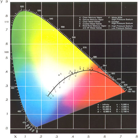 Chromaticity
Chromaticity standards.
bandgap
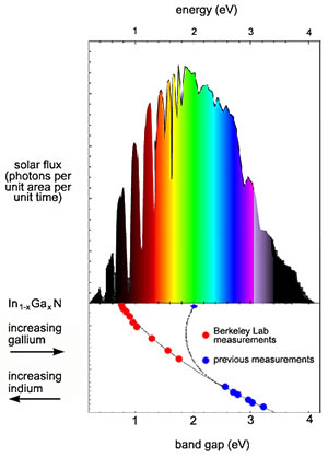 Bandgap
Bandgap Voltage vs Color
An unexpected discovery could yield a full spectrum solar cell.
The serendipitous discovery means that a single system of alloys incorporating indium, gallium, and nitrogen can convert virtually the full spectrum of sunlight ( from the near infrared to the far ultraviolet ) to electrical current.
Bright and efficient LED lamps! Efficiency of some good ones and some runner-ups in lumens per watt, millicandela and beam angle ratings for most of these, where to get most of these. Also links into Agilent / Hewlett Packard's LED web site.
Light Measurement Handbook
A very neat book that describes in graphical detail the relationship
between gradient and luminous fluxes and Irradiance and Illuminance.
This is a free publication/advertisement on all aspects of light measurement.
photomet
Definition of terms used in Radiometric and Photometric measurements.
conversion

How do I convert between candlepower and watts?
For a 15deg angle the steradian angle is .01704 solid degrees and
for a 30deg angle the steradian angle is .06699 solid degrees.
2000mCd with a 15 degree divergence angle and an electric power consumption of .06W. the equivalent lumens is:
2Cd * .01704lumen/Cd = .03408 lumens
.03408 lumens / (673 lumens/W) = 50.6uW of light
The electric to light efficiency is:
50.6uW / 60mW = .84% efficient
If someone can show me where I have failed in these calculations I would appreciate it. I'm not comfortable with the theory.
Thanks!
Rules of Thumb.
Lamp Type lumens/Watt Efficiency
White LEDs 15 2%
Incandescent Lamps 20 3%
Colored Visible Light LEDs 20 3%
Mercury Vapor Gas Discharge Lamps 47 7%
Fluorescent Gas Discharge Lamps 67 10%
Electro Luminescent Light Sources 80 12%
Metal Halide Gas Discharge Lamps 101 15%
Sodium High Pressure (HPS) Lamps 135 20%
Sodium Low Pressure (LPS) Lamps 168 25%
Lamp Type lumens/Watt Efficiency Reference
Incandescent Edison's first lamp 4 to 1 0.6% to .15% Grainger lighting definitions
Incandescent Standard Lamp 15W 8 1.2% Grainger's GE# 12658
Incandescent Standard Lamp 40W 11 1.6% Marks (3) Table 12.5.3
Incandescent Standard Lamp 40W 13 1.9% Grainger's GE# 13255
Incandescent Halogen Lamp 50W 14 2.1% Grainger's GE# 16746
Incandescent Standard Lamp 60W 14 2.1% Grainger's GE# 41026
Incandescent Standard Lamp 100W 17 2.5% Grainger's GE# 41034
Automotive Standard Lamp 21W 24V 18 2.6% Clare GE# 13498
Incandescent Halogen Lamp 90W 18 2.6% Grainger's GE# 16746
Incandescent Halogen Lamp 90W 18 2.6% Grainger's GE# 16746
Automotive Standard Lamp 21W 12V 21 3.2% Clare GE# 12498
Incandescent Standard Lamp 24 to 6 3.6% to 0.9% Lighting Fundamentals
Automotive Halogen Lamp 22W 12V 25 3.7% Clare Philips
Mercury Vapor 40Watt 28 4.2% Grainger's GE# 12460
Mercury Vapor 75Watt 37 5.5% Grainger's GE# 12461
LED White 40 5.9% Elektronik
Mercury Vapor 100Watt 40 5.9% Grainger's GE# 12467
Mercury Vapor 250Watt 48 7.2% Grainger's GE# 32127
Mercury Vapor 175Watt 49 7.3% Grainger's GE# 14111
Fluorescent Lamps 40T12 49 7.3% Marks (3) Table 12.5.4
Fluorescent Compact Double 10W 50 8.2% Grainger's GE# 30031
Mercury Vapor 400Watt 56 8.4% Grainger's GE# 23998
Fluorescent Power Groove PG17 60 8.9% Grainger's GE# 47732
Fluorescent Compact 20W 60 8.9% Philips BC-SLS 20
Mercury Vapor 60 to 25 8.9% to 3.7% Lighting Fundamentals
Fluorescent Compact Triple 18W 62 9.2% Grainger's GE# 10449
Fluorescent Compact Triple 26W 62 9.2% Grainger's GE# 12278
Mercury Vapor 1000Watt 63 9.4% Grainger's GE# 24191
Mercury Vapor 63 to 24 9.4% to 3.6% Marks (3) Table 12.5.2
Fluorescent Compact Double 18W 64 9.6% Grainger's GE# 30035
Fluorescent Compact Triple 13W 65 9.7% Grainger's GE# 11982
Fluorescent Compact Double 26W 65 9.7% Grainger's GE# 30042
Fluorescent Compact Triple 32W 69 10% Grainger's GE# 12781
Fluorescent Compact Double 13W 69 10% Grainger's GE# 30035
Metal Halide Halarc 32Watt 78 12% Grainger's GE# 12651
Metal Halide Halarc 70Watt 79 12% Grainger's GE# 12377
Electro Luminescent type TC 80 12% World Products Inc
Metal Halide Multi-Vapor 175W 80 12% Grainger's GE# 18902
Fluorescent Lamps 40T12 84 12% Grainger's GE# 15079
Sylvania Xenarc Auxiliary Kit 84 12% Sylvania web site
Metal Halide Halarc 100Watt 90 13% Grainger's GE# 12381
Metal Halide Multi-Vapor 400W 90 13% Grainger's GE# 18904
Metal Halide Halarc 175Watt 95 14% Grainger's GE# 11420
Sodium Low Pressure (LPS) 18W 100 15% Grainger's GE# 21294
Metal Halide Multi-Vapor 1000W 110 16% Grainger's GE# 18904
Metal Halide 115 to 50 17% to 7.4% Lighting Fundamentals
Metal Halide 125 to 69 19% to 10% Marks (3) Table 12.5.2
Sodium Low Pressure (LPS) 35W 131 20% Grainger's GE# 21296
Sodium Low Pressure (LPS) 55W 139 21% Grainger's GE# 21297
Sodium High Pressure (HPS) 140 to 73 21% to 11% Marks (3) Table 12.5.2
Sodium Low Pressure (LPS) 90W 142 21% Grainger's GE# 21298
Sodium Low Pressure (LPS) 135W 163 24% Grainger's GE# 21299
Sodium Low Pressure (LPS) 180W 183 27% Grainger's GE# 30203
Sodium High Pressure (HPS) LUCALUX 35W 64 9.6% Grainger's GE# 11668
Sodium High Pressure (HPS) LUCALUX 50W 80 12% Grainger's GE# 11345
Sodium High Pressure (HPS) LUCALUX 70W 91 14% Grainger's GE# 11339
Sodium High Pressure (HPS) LUCALUX 100W 95 14% Grainger's GE# 11250
Sodium High Pressure (HPS) LUCALUX 150W 107 16% Grainger's GE# 13252
Sodium High Pressure (HPS) LUCALUX 400W 128 19% Grainger's GE# 44054
Sodium High Pressure (HPS) LUCALUX 1000W 140 21% Grainger's GE# 44058
lighting
Solar Lighting.
1ft² of sunlight from a single mirror contains about 80W of light.
Small 1ft² mirror tiles deliver the equivalent light output of:
80W / 3% = 2700W of light from incandescent bulb.
future
The Future.
Process Chemicals.
 Go back to Red Rock Energy
<redrok@redrok.com>
 IEA SolarPACES Program