
This monograph got started when Wally Bently <bently@flash.net> asked a question about the economics of large scale water distillation. I am a little fuzzy about the details right now but the idea was that clean water was not available near the Rio Grand. Something about contaminated wells. The cost of bottled water was expensive. The question was how much it would cost to make distilled water and compare this to the cost of the bottled variety.
A number of messages were exchanged regarding the water wells and the different types of bottled water available and the need for a more cost effective replacement. I have kept two messages that I think encompass the high powered solar still portions of the thread.
I am including these messages here.
| Subject: | [SOLAR] Re: Thoughts on economics of Solar Water Still |
| Date: | Fri, 03 Oct 1997 07:26:45 -0700 |
| From: | Duane Johnson <redrok@redrok.com> |
| Reply-To: | solar-concentrator@cichlid.com |
| Org: | Red Rock Energy |
| To: | Wally Bently <bently@flash.net>, solar-concentrator@cichlid.com |
| Groups: | alt.solar.thermal |
Hi Wally and all;
Wow, what an idea.
Wally Bently <bently@flash.net> wrote:
| > | SOME SOLAR WATER STILL ECONOMIC THOUGHTS |
| > | This posting is based on the observation that five gallons of distilled water sells for $7.33 plus a $3 deposit for the five gallon container in the Dallas/Fort Worth metroplex. Spring water (whatever that is?) sells for $8.23 plus a #3 container deposit. |
| > | This raised the following question in my mind. What is the maximum price for purchasing or selling a solar powered water still? Obviously distilled water is valued at: $7.33/5 gallons = $1.46/Gallon (U.S. gallons) One "solar still" manufacturer claimed their 40 square feet line focused solar collector would produce an average 2.9 gallons of distilled water per day in southern California. A yearly total would be: (2.9 gallons/day)(360 days/year) = 1,044 gallons/year yearly water value = (1,044 gallons)(1.46) = $1,524 Their "solar still" purchase price FOB California plant was $2,900 (1989 year figures). Assuming there is no operating cost, This would suggest a break-even point at a little over 2 years with current interest rates. |
| > | There "Solar still" concept also had the byproduct of thermal heat from condensing the steam being recaptured by a hot water heater. Question is what is the value of that heat. Assuming the heat of condensation is 8,000 BTU/gallon of water and is recaptured, the heat would be:
yearly heat value = (1,044 gallons)(8000 BTU)/gallon)= 8.32 million BTU. Natural gas sells for about $3 for a million BTU of heat. This puts the annual heat value recovery at $24. While not significant, it is a factor to consider. |
My natural gas costs a little more but we are in the same ball park here. What is more important to me is that the value of the distilled water can be expressed as:
($1.48/gal) / (8000BTU/gal) = $0.000185/BTU = $185.00/millionBTU
$185.00/gal / $3.00/gal = 62 to 1 cost ratio.
OK, lets use this commercial still and lets say it has a depreciation of 10 years. Since it produces 1044 gallons of water:
$1.48 * 1044gal/yr = $1545/yr
$2900 - ($2900 / 10) * 10 = $0.00 over 10 years
$185.00/gal / $0.00/gal = Infinite to 1 cost ratio.
| > | To be market competitive, can a better "solar still" be built with a larger collection area with greater efficiency in production of distilled water? I would suggest it may be economically possible to build a solar still with 10 times the solar collector area that would produce 10 times the distilled waters and still be marketable for $2,900. What do you think? This would produce 10,440 gallons/year of distilled water with a value of $15,244. The cost of production would be 15 cents a gallons. |
| > | Such a solar still to provide that heat would be 8 feet across and 50 feet long (about the length of a large houses) and could fit in many back yards. |
| > | The next question is? Can you find enough buyers for that distilled water by distributing through grocery stores/etc. or a single user of that amount of water? |
| > | Does anybody know how much distilled water the average individual in a home uses? |
I think that the still can be made better. Higher performance stills incorporate some form of heat exchanger or regenerator. It would seem that at least 75% of the heat used to boil the water can be recovered to preheat the incoming cold water which is also used in the condenser. This suggests that only 25% of the heat needs to be added per cycle.
If heated using natural gas the regenerator still only needs 2000BTU, (8000 * 25%), to boil one gallon of water. This would suggest that the fuel cost for each boiled millionBTU would be $0.75, ($3.00 * 25%).
Compared to the cost of natural gas, at an equivalent regenerated value of $0.75, this is a lot of profit.
$185.00 / $0.75 = 250 to 1 cost ratio.
Let me use another example based on my 200'^2 heliostat. After inefficiencies in both the mirrors and the secondary reflector/receiver I was estimating a delivery of 10KW thermal. Further using a still with 75% thermal regeneration this is equivalent to 40KW. Lets assume that I get 2000 solar hr/yr. I then get a basic yearly water boiling rate of:
40KW * 2000hr/yr = 80 MWhr/yrLets say my heliostat costs $5000 and the still costs $5000. If the depreciation for the equipment is 10 years then the first years net value is $48900. Let's not consider depreciation. Lets just consider paying for the investment all in the first year.
80MWhr/yr * 3.415BTU/Whr = 273 MBTU/yr
273MBTU/yr / 8100BTU/gal = 33700gal/yr
33700gal/yr * $1.48/gal = $49900 /yr
$49900 - $10000 = $39900 for the first year.
Now compare this with just selling the energy as electricity to the power grid. (Remember that as yet we don't know how to generate this electricity.) I will try to guess.
Now I don't get thermal regeneration.
10KW * 2000hr/yr = 20 MWhr/yr
20MWhr/yr * 10% = 2 MWhr/yr
2.0MWhr/yr * $.06/KWhr = $120.00/yr
What's wrong with this picture. On the one hand I get $39900 and on the other hand I get $120.00.
Of course one could dispense with the solar equipment all together and fire up the still electricity but then you wouldn't get the "green" advertisement potential. Besides the depreciation pays for the equipment cost.
What does bottling equipment cost? Where's my Thomas Registry?
Where is my mistake? Other than there is no market yet.
| Subject: | Re: Thoughts on economics of Solar Water Still |
| Date: | Mon, 06 Oct 1997 06:32:55 -0700 |
| From: | Duane Johnson <redrok@redrok.com> |
| Org: | Red Rock Energy |
| CC: | <mas@ucla.edu> |
| groups: | alt.solar.thermal |
Hi Michael;
| > > | What's wrong with this picture. On the one hand I get $39900 and on the other I get $120. |
| > | I thought that a lot (all?) of the "distilled water" was really either de-ionized (via ion-exchange) or reverse osmosis. No need to deal with "heat" at all.... |
I just checked. When the water is labeled as "distilled" it has to be distilled. Of course this could be from a vacuum process at a lower temperature. Essentially the process of distillation requires some form of vaporization and condensation to be sold as distilled.
Some De-ionized water used osmosis techniques while others use chemical methods.
Finally soft water simply exchange hard ions such as calcium with soft ions such as magnesium.
When doing a water resistivity test for chemical purity generally distilled water is the best with de-ionized second and of course followed by soft water.
The best stills have de-gasification at high temperature before boiling.
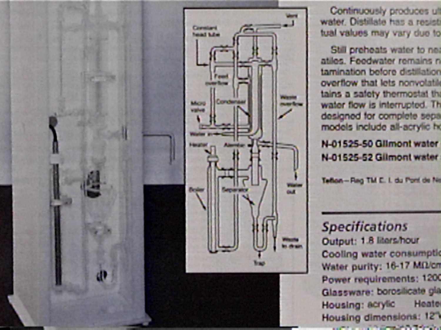
Boiling Water Heat Exchanger Still with Regeneration.
I have been emailing with Nick Pine <nick_pine@verizon.net> about water stills. We have been looking into Multiple Effect Humidification Water Stills. In our discussions greenhouse type water stills have come up. The thought that multiple humidification effects could be used in greenhouse stills would make them more efficient.
The large commercial multiple humidification effect still, described later, uses heat exchangers to regenerate the available heat used to evaporate the water. This type of still is able to produce many times more water than a simple still for the same amount of energy.
I had an idea!
Maybe the green house still could be built sort of upside down. A mirror puts the heat into the bottom which is the hottest level and the latent heat passes up through the layers to the top where the cold water is introduced.
Extra heat is easily added in the top. This added heat doesn't directly add to the distillation rate. The top solar collector does add heat that would be lost through the tube in tube heat exchanger.
The cool water is heated through the heat exchanger. The top is the coolest because this is where the cold regenerated water enters the evaporator. Each section adds heat from the sun to the water as it passes down through the collectors. By using the appropriate opacity the heat from the sunlight can be tailored to the correct temperature at the right water level for maximum throughput. Some sunlight passes through each layer in both direction until it is converted to heat.
Also latent heat passes upward through evaporation from below and condensation above.
I will describe a multiple effect still using 3 evaporative surfaces and 3 condensing surfaces. The basic construction detail is composed of several cone shaped structures stacked inside a barrel shaped container.
For 3 effects there are 4 cones.
The example described here uses 3 evaporative effects but many evaporative effects could be used in a real still.
  |   |   |   |            |   |   |        <----
  |   |   |   |   Sunlight |   |   |     ____________
  |   |   |   |    In From |   |   |    / __________ \
  v   v   v   v     Top    v   v   v    ||          ||
 _______________________________________||_____     ||
 |   \||_v^v^v^v^v^v^v^v^v^v^v^v^v^v^v^_o_/   |   ^ ||
 |    || \___Coolest   __ Weight   ___/       |   | || Although the
 |    ||     \___     /  \     ___/           |   | || cones look like
 |    o Selective\___ \__/ ___/Cone           |     || up side down
 |     o      Surface\____/Condenser          |     || Devo hats they
 |    o                                       |     || are meant to be
 |___        Water   |  o |                ___|     || smooth cones.
 |   \^v^v^v^v^v^v^v^| o  |^v^v^v^v^v^v_||/   |     ||
 |       \___Cooler  |  o |Funnel  ___/ ||    |     ||
 |           \___    | o  |    ___/     ||    |     ||
 |               \___ \  / ___/Cone      o    |     ||
 |                   \_||_/Condenser    o     |     ||
 |                     ||                o    |     ||
 |___        Water   | o  |                ___|     ||
 |   \||_v^v^v^v^v^v^|  o |^v^v^v^v^v^v___/   |   ^ ||
 |    || \___Hot     | o  |Funnel  ___/       |   | ||
 |    ||     \___    |  o |    ___/           |   | ||
 |    o          \___ \  / ___/Cone           |     ||
 |     o             \_||_/Condenser          |     ||
 |    o                ||                     |     ||
 |___        Water   |  o |                ___|     ||
 |   \^v^v^v^v^v^v^v^| o  |^v^v^v^v^v^v_||/   |     ||
 |       \___Hotest  |  o |Funnel  ___/ ||    |     ||
 |           \___    | o  |    ___/     ||  ---->   ||
 |      Selective\___ \  / ___/Cone     ||________  ||
 |            Surface\_||_/Condenser    \________ \ ||
 |                     ||                     |  || ||
 |___________________| o  |___________________|  || ||
 ^    ^    ^    ^     \ o/_____________________  || ||
 |    |    |    |      \______________________ \ || ||
 |    |    |    |           ^       ^         || || ||
 |    |    |    |           |       |       / || || ||
 |    |    |    |           |       |     /   || ||/ /
 |    |    |    |           |       |   /   | || || /
 |    |    |    |           |       | /     | ||/|| |
-|----|----|----|-----------|-------/       v || || |
 |    |    |    | Sunlight  |     /          /|| || |
 |    |    |    |  In From  |   /  Tube     / || || |
 |    |    |    |   Bottom  | /    in       | || || |
-|----|----|----|-----------/      Tube     | || || |
 |    |    |    |         /        Heat     | || || |
 |    |    |    |       /          Exchanger| || || |
 |    |    |    |     /Reflector            | || || |
 |    |    |    |   /                       | || || |
 |    |    |    | /                         | || || |
-|----|----|----/                           | || || |
 |    |    |  /                             \ || || |
 |    |    |/                                \|| || |
 |    |   /                                   || || |
 |    | /    Purified        _________________||\|| |
-|----/      Condensate Out / _________________/ || \
 |  /                       ||       ____________||\ \
 |/         Waste Water Out || |    / ____________/ ||
/                           || |    || |      ______||
      Contaminated Water in || |    || |   ^ / ______/
                            || v    || v   | ||
The operation can be best described by following the heat as it passes through the various thermal resistances and evaporation/condensation cycles.
Nick is much better than me at these calculations but I will try. I'm sure he will correct me when I falter.
Here are the assumptions:
| 1. | Lets assume that the thermal mass of the water is constant through the temperature range at 1btu/(lb degF). |
| 2. | Lets assume that the latent heat of vaporization is constant through the temperature range at 1000btu/lb. |
| 3. | Assume that all the liquid water in a cone assembly is at the same temperature. This is valid because the water should be convecting since the thermal input is at the bottom. If there is a temperature difference between the top and bottom it will be small. |
| 4. | Lets ignore the thermal contribution of the top collector. |
| 5. | Lets assume the cold water entering the top has been heated to the ideal operating temperature. The maximum temperature when working with PVC is about 160F. Any hotter and things start to melt. |
| 6. | Lets start out with using two humidification effects which then uses 3 cone assemblies. |
| 7. | Lets assume the condenser and liquid water surface areas are each 1 square foot. |
| 8. | Lets assume the solar thermal input at the bottom is 100 Watts or 341.2btu/h |
---> ccc wwwwwwwwwww aaaaaaaaaaa ccc wwwwwwwwwww aaaaaaaaaaa ccc wwwwwwwwwww
---> ccc w  WATER  w a   AIR   a ccc w  WATER  w a   AIR   a ccc w  WATER  w
---> ccc w  ---->  w a  ---->  a ccc w  ---->  w a  ---->  a ccc w  ---->  w
---> cCc w /     \ w a /     \ a cCc w /     \ w a /     \ a cCc w /     \ w
Heat cOc w^       |w a^       |a cOc w^       |w a^       |a cOc w^       |w
 In  cNc w|       vw a|       va cNc w|       vw a|       va cNc w|       vw
---> cEc w \     / w a \     / a cEc w \     / w a \     / a cEc w \     / w
---> ccc w  <----  w a  <----  a ccc w  <----  w a  <----  a ccc w  <----  w
---> ccc wwwwwwwwwww aaaaaaaaaaa ccc wwwwwwwwwww aaaaaaaaaaa ccc wwwwwwwwwww
|___             Temperature Drops Through the Cone Stacks
|    \
|     \
|      \ _____
|             \_____
|                   \__
|                      \__
|                         \__
|                            \__
|                                \
|                                 \
|                                  \ _____
|                                         \_____
|                                               \__
|                                                  \__
|                                                     \__
|                                                        \__
|                                                            \
|                                                             \
|                                                              \ _____
|                                                                     \_____
+----------------------------------------------------------------------------
| 1. Cone | The temperature drop across the plastic cone material. The conductivity of PVC plastic is probably about: 5 Btu in/(ft^2 hr F). I am assuming the plastic is .006" thick. This would imply a temperature difference across the plastic cone material of: Other materials such as concrete or stainless steel could also be used. |
| 2. Water | The temperature drop across the evaporating water. This is probably much lower than the thermal conductivity of the water. It's more related to the rate of convection of the water. Ideally the convection rate should be as high as possible. |
| 3. Air | The temperature drop across the humid air interface between the cones. This is probably much lower than the thermal conductivity of the air. It's more related to the rate of convection of the air between the cones. Ideally the convection rate should be as high as possible. |
I think this concept, using the tube in tube heat regenerator, may improve the operation of direct evaporation greenhouse type of water still.
Hi tech selective absorption surfaces could be used at the top and bottom. Maybe plastic surfaces.
I am studying this still to enhance it's performance and build it using mostly PEX tube in tube heat exchangers.
SOLAR DISTILLATION UTILIZING MULTIPLE-EFFECT HUMIDIFICATION
authored by:
Carl N. Hodges, T. Lewis Thompson
John E. Groh, & Donald H. Frieling
from:
The University of Arizona
Solar Energy Laboratory of the
Institute of Atmospheric Physics
1966 01 31
Online at babel.hathitrust.org
You can read it here.
Or get a copy at Amazon for $19us.
This project developed a pilot plant at Puerto Penasco, Sonora, Mexico. The plant produces over 5000 gallons per day of distilled water using 10400 ft^2 of solar collector area. The report does a cost extrapolation to a plant that can produce 1 million gallons per day.
The basic principal of operation of this process is to pass heated water over a material with high surface area. Kind of doughnut shaped objects. This material is loosely packed in a vertical column. Air is moved upward through this column and is heated and humidified. The air is moved to a second column where cool water condenses the water out of the humidified air as distilled water.
The process is thermally efficient by reusing the solar generated heat as much as 8 times. The latent heat of evaporation contained in the hot water is transferred to the water vapor and deposited to the cool water in the condenser. The water in the condenser is heated with the solar collectors adding what ever heat was lost in the process.
The quantity of water that can be purified in this manner far exceeds the quantity obtained in a conventional solar still.
I am interested in building a humidification still of my own. I have a few special requirement for this still so it can be used in conjunction with my heliostat array solar collectors:
| 1. | Must be simple to build. Preferably using the materials easily obtained at the building center. |
| 2. | Must have a heat exchanger built into the water heater assembly. |
| 3. | If possible, the air should move through the system by gravity convection. |
| 4. | Must have a high temperature de-gasification section to remove dissolved VOCs, Volatile Organic hydroCarbons. |
| 5. | Any controls should be simple and fail-safe. |
| 6. | Everything should be able to be made using conventional hand tools. |
As an experiment I wanted to see if I could make a low powered still that could be used by a single family for purification of drinking and cooking water. Hopefully it will make a few gallons per day.
My first try at building the humidification still is based on 4" PVC plastic sewer pipe that I obtained from my building center. This pile and the associated connector pieces are plastic solvent-welded together. Some of the pieces were modified by turning them in my lathe. These pieces could have been modified using a hand file.
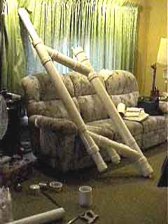
Humidification Still.
ASCII schematic of Humidification Still.
        ___          ___
       / _ \        / _ \
       || ||        || ||
       || ||        || ||
      ||||          ||
      ||||          ||
      /  \         ||||
     /    \        ||||
    /  4"  \       /  \
   /to 1/2" \     /    \ 3" to 1/2" Reducer
  / Reducer  \   /      \
 /            \ /  Gas   \
 ||          || || Vent ||
 || Float    || ||      ||
  | Valve    |   |      |
  |  _ || _  |   |      |                  |
  | | |||| | |   |      |                  V
  |^v^v^v^v^v|   |Water | ----------------------------------
  | |_||||_| |   |Level  \ Inlet Differential Water Pressure
  |    ||    |   |^v^v^v|\\ --------------------------------
  |    ||    |   |      | \\               ^
 ||    ||    ||  |Thermo|  \\              |
 ||    ||    ||  |Stat  |   \\Over
 \_____||_||__/  |      |    \\Flow
       || ||     |Water |     \\Pipe
Water  || ||     |Heater|      \\
From   || ||     |      |       \\
Main   || ||     |      |        \\
_______// ||     |      |4"x3"    \\
_______/  ||     |      | Reducer  \\
          ||   |||      |||Spacer   \\
  ------  ||  ||||      ||||         \\
  ||||||-|\/| ||||      ||||          \\
  ||||||-|/\| |  |      |  \           \\
  ------  ||  |  |      |   \4"x4"x4" Y \\
Solenoid  ||  |  |      |    \           \\
Operated  ||  |  |      |     \           \\
Valve     ||  |  |      |      \           \\
          ||  |  |      |       \           \\
          ||  |  |      |        \           \\
          ||  |  |      |         \           \\
          ||  |  |      |         \\           \\
          ||  |  |      |          \      Heated\\
          ||  |  |      |           \     Water  \\
          ||  |  |      |            \    In  ____||______
          ||  |  |      |  \\         \      /    ||      \
          ||  || |      | ||\\         \  4" || |^||V|   ||
          ||  || |      | ||  \         \ Cap|| | || |   ||
          ||   | |      | |    \         \    | | || |   |
          ||   | |      | |     \         \  || | || |   ||
          ||   | |      | |      \         \\|| \____/   ||
          ||   | |      | |       \         \\  P Trap    |
          ||   | |      | |        \          Porous //\\\|
          ||   | |3"    | |4"       \  //\\\         \\///|
          ||   | |Pipe  | |Pipe      \ \\///   //\\\      |
          ||   | |      | |          \\        \\///      |
          ||   | | C    | |           \  //\\\Lava  //\\\ |
          ||   | | o    | |            \ \\///      \\/// |
          ||   | | n    | |             \                 |
          ||   | | d    | |              \    Rocks//\\\  |
          ||   | | e    | |               \        \\///  |
          ||   | | n    | |                \ //\\\        |
          ||   | | c    | |       4"x4"x4" Y\\\///        |
          ||   | | e    | |                  \      //\\\ |
          ||   | | r    | |                  ||     \\///||
          ||   | |      | |                  ||//\\\     ||
          ||   | |      | |                   |\\///     |
\  /\  /\ |/\  /\| /\  /\ |/\  /\  /\  /\  /\ |/\  /\  /\| /
\\//\\//\\//\\//\\//\\//\\//\\//\\//\\//\\//\\//\\//\\//\\//
 \/  \/  \/| \/| \/  \/ |\/  \/  \/  \/  \/  \/  \/  \/  \/
          ||   | |      | |                   |//\\\     |
          ||  || |      | ||              4"  |\\/////\\\|
          ||  || |      | ||              Pipe|     \\///|
          ||  |  |      |  \                  | E //\\\  |
          ||  |  |      |   \4"x4"x4" Y       | v \\///  |
          ||  |  |      |    \                | a        |
          ||  |  |      |     \               | p  //\\\ |
          ||  |  |      |      \              | o  \\/// |
          ||  |  |      |       \             | r        |
          ||  |  |      |        \            | a //\\\  |
          ||  |  |      |S       \\           | t \\///  |
          ||  |  |      |p        \\          | o        |
          ||  |  |      |a         \\4"x4"x3" | r   //\\\|
          ||  |  |      |c           \ Y      |//\\\\\///|
          ||  |  |      |e \          \       |\\///     |
          ||  |  |      |r \\          \      |          |
          ||  ||||      ||||\\          \     |    //\\\ |
          ||  ||||      |||| \           \    |    \\/// |
          ||   |||      |||  |            \   |//\\\     |
          ||     |      |    |            \\ ||\\/////\\\||
          ||    ||      ||   |             \\||     \\///||
          ||    ||      ||   |              \\            |
          ||    \___||___/   |              Porous//\\\   |
          ||        ||3" Cap |     \\  //\\\      \\///   |
          ||  Cold  ||       |     |\\ \\/////\\\Lava     |
          ||  Water ||       |     | \\     \\///    //\\\|
          ||  In    ||       |  __ |  \ //\\\   //\\\\\///|
          \\________//   P   | /  \|   \\\////\\\\///Rocks|
           \________/    Trap|v|||||    \   //\\\         |
                            || ||||||    \  \\///  //\\\  |
                            || ||||||     \        \\///  |
                 Distillate \___||__/      \  //\\\  //\\\|
                 Out            ||          \ \\///  \\///|
                                || 4"X4"X4" Y\     //\\\  |
                                             ||    \\/// ||
                                             || ____     ||
                                              |/    \P   |
                                          4" |||^||v|Trap||
                                          Cap||| || |^v^v||
                                             \___||_______/
                                  Waste Water Out||
                                                 ||
The distillation through humidification process operates by a combination of air humidification and condensation. Here is the sequence by which this happens:
| 1. | Cold contaminated water is introduced to the bottom of the condenser column. |
| 2. | The water vapor in the hot humid air from the evaporator condenses on the cold condenser element. This delivers latent heat to the water and heats it up. |
| 3. | The pre-heated water rises to the heater section. Extra heat is added to the water to compensate for the inevitable heat losses and temperature drops in the system. |
| 4. | Heated water flows through the overflow pipe and into the evaporator. The water flows down and wets the surface of the porous lava rock. |
| 5. | Cool air moves upward through the lava rock. As the hot water evaporates into the air the excess water is cooled by the air and the air is heated and humidified. |
| 6. | The excess water flows down and out the waste pipe. |
| 7. | Hot humid air is less dense than cold dry air. This causes the air to rise and flow over to the condenser unit. The hot humid air is light for 2 reasons. Hot air is less dense through thermal expansion. Humid air is lighter than dry air because the water molecule has a lower molecular weight than either nitrogen or oxygen. The combination is even lighter. |
| 8. | The cold water is admitted using the solenoid operated valve. This valve is activated when the water above the heater is lower than the set point. |
| 9. | The cold water reservoir filled to a level just above the water level in the heater overflow pipe. The level is maintained using a float valve similar to that used in a bathroom toilet. |
| 10. | The cold water flow is regulated by the height difference between the water levels in the two reservoir. |
Greg Lesher has come up with a nice method to distil salt water for gardening.
He is selling a digital "how to" book on how to make the simple still and many variations.
$15us
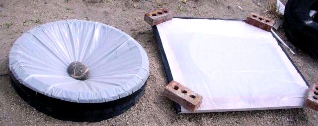
http://www.seawatertogarden.com/
A friend of mine has a hand dug, ER pounded, water well. Here are the particulars:
| 1. | The well is about 80 feet in depth. |
| 2. | It uses a 2.5" well casing. |
| 3. | The well pump is a deep well jet pump. |
This well has a problem with water flow. It turns out that jet pumps are inefficient when used with wells that have limited flow. The problem is that the jet pump is not a constant displacement pumping mechanism. With low flows all that happens is that water is pumped through the jet and little extra water is sent up the pump.
We have been looking for a submersible pump that would fit into the 2.5" casing to no avail.
airlift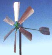 Air Lift Technologies.
This is a description of a pneumatic air lift water pump.
                      ______
                     /waaawa\ <---------------------
                     |a|---\a\     a              ^
 __________          |a|    \a\  a  a             |
/          \         |a| |    w       |           |
| Air   a  |______   |w| |^v^v^v^v^v^v|           |
|  Pump.  a aaa aa\  |a| | Water Tank.|           |
|       a  |-----\a\ |a| |  w   w     |           |
\__________/     | | |a|  \___w____w_/            |
                 |a| |w|                          |
  a=air.         |a| |a|                          |
  w=water.       |a| |a| "H" Height to lift water |
                 | | |a|     above water table.   |
                 |a| |w|                          |
          3/8"   |a| |a|   1/2"                   |
  Down Air line. |a| |a| Up Water line.           |
                 | | |a|                          |
                 |a| |w|                          |
                 |a| |a|                          |
                 |a| |a|                          |
                 | | |a|                          |
                 |a| |w|                          |
                 |a| |a|                          |
  water Table.   |a| |a|                          v
v^v^v^v^v^v^v^v^v| |^|a|v^v^v^v^v^v^v <-------------
                 |a| |w|                          ^
                 |a| |a|                          |
                 |a| |a|                          |
                 | | |a| "P" Pressure depth       |
                 |a| |w|      below water table.  |
                 |a| |a|                          |
                 |a| |a|                          v
                 \ \_|a| <--------------------------
 "T" Fitting. --> \aaaw|                          ^
                   --| |                          |
                     | |                          |
                     | | "S" Screen pressure.     |
                     |w|         (About 20')      |
                     | |                          |
                     | |                          |
                     | |                          v
 Sand Screen. -----> =w= <--------------------------
                     ===
This pump uses some very simple construction techniques. The operation is a bit more complicated.
When installing this pump in a well several dimensions must be determined in order for proper operation.
Before air pressure is applied to the system the water in the Up water line is even with the water table. The T will be at a depth P feet below the water table. Water exerts about .42 psi for each foot of depth. If P*.42 psi of air pressure is applied to the down air line air will bubble out of the T and try to rise up the water line. When the air rises it will push an equal volume of water up the water line. P*.42 psi of pressure can support P feet of water in the up water line.
With further additions of air the water will continue to rise in the up line. Eventually some water will leave the up line and fill the tank. When this water leaves more water will come up from the screen. The percentage if water in the up line is approximately:
Water % = P/(P+H) * 100
There is always a balance between the volume of air and the volume of water in the line.
There is always an oscillation in the movement of the water in the up line. In the event there is to much water in the up line air may displace water in the screen line. If this happens some air may be lost. If the screen length is to short there will be an excessive amount of air loss.
As the air needed to do the lifting is compressed more SCFM air is needed than would be indicated. The before compression air volume to water volume ratio is:
SCFM = (H*.42)/14.7 This is in standard cubic feet per minute.
This pump is not suitable for low flow applications because it requires that the foot of the well be at least 20 feet lower than the height if the water level in the well. Also it is still not a positive displacement pump and doesn't work where the flow is limited.
gaiatech
And Another Bubble Pump or Tromp.
This pump is useful with low heads and high volumes. Check it out.
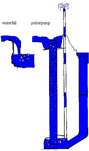 GAIATECH, working with nature PULSER pump. Dig the POWER!
pendulum
Pendulum Pump.
 Veljko Milkovic' has a patent for this interesting hand operated water pump.
I have been thinking about a different type of pump. The pump I have in mind has constant displacement capabilities and works with wells that have limited flow.
The prototype pump consists of two parts:
| 1. | The out of the well equipment. |
| 2. | The down the well pump parts. |
The well pump prototype I am working on is constructed with all copper or brass plumbing fittings. The basic requirement is that everything fit within a 2.5" well casing. This pretty much limits the maximum outside diameter to less than 2.375". With this constraint the larger diameter brass tubing is a nominal 2.0" diameter and the smaller tubing one size smaller.
Sequence of operation:
| 1. | Start the power piston downward past the Small Holes. |
| 2. | Continue downward forcing the water to push the slave piston downward. |
| 3. | The slave piston pulls the pump piston downward. |
| 4. | When the power piston moves downward some of the water moves past. This is caused by the total volume under the pump decreasing. |
| 5. | The power piston moves up to the top and uncovers the small holes. |
| 6. | The spring pushes the pump piston upward bringing water to the top. |
| 7. | Water exits the small holes. |
| 8. | Since the volume under the power piston increases water is drawn past the slave piston. |
| 9. | Repeat the cycle. |
Description of a hydraulically actuated water pump.
      ____
   ---    ---
  /          \
 /            \     Motor Driven Flywheel
|              |    With a Crankshaft
|      ()    ()|    and Rod Journal.
|            rr|
 \          rr/
  \         rr
   ---____-rr
           rr
          rr   rr = Connecting Rod.
   |      rr|
   |     rr |   p = Cup Shaped Power Piston.
  ||     rr ||                      _________
  ||    rr  ||                   ---         ---
  /|    rr  |\                  /               \
 / |   rr   | \                /                 \
|| |   ()   | ||              /   Water Level.    \
|| |  pppp  | ||             |v^v^v^v^v^v^v^v^v^v^v|
 | | p    p | |---------------                      |
 | Op      pO                                       |
 | |        | |---------------    Pressure Tank.    |
|| |        | ||             |                     |
|| |        | ||              \                   /
 \ |        | /                \                 /
  \|        |/                  \               /
  ||        ||  O = Small Holes. ---_________---
  ||        ||
   |        | <---- Power Cylinder.
  ||        ||
  ||        ||
   \        /
    \      /
    ||    ||
    ||    ||
     |    |
\  /\| /\ |/\  /
\\//\\//\\//\\//
 \/  \/  \/  \/
     |    |         Water Table.
v^v^||    ||v^v^v^v^v^v^v^v^v^v^v^v^v^v^v^v^v^v
    ||    ||
    /      \
   /        \
  /          \
 /            \
||            ||
||            ||
 |            | <-- Pump Cylinder.
 |p          p|
 | p   rr   p | p = Cup Shaped Pump Piston.
 |  pppppppp  |
 |   s rr s   |
 | s   rr     |
 |s    rr     | r = Rod to Connect the
 | s   rr     |     Cupped Pistons Together.
 |   s rr s   |
 |     rr   s |
 |     rr    s| s = Stainless Steel Spring.
 |     rr   s |
 |   s rr s   |
|| s   rr     ||
||s    rr     ||
 \ s   rr     /
  \  s rr s  /
  ||   rr   ||
  ||   rr   ||
   |   rr   | <---- Slave Cylinder.
   |p  rr  p|
   | p rr p |   p = Cup Shaped Slave Piston.
   |  pppp  |
   |   rr   |
   |        |
   |        |
   |        |
   |        |
   |        |
   = = = = =  <---- Sand Screen.
    = = = = =
hydro
Hydro Systems.
A hydro system usually consist of a dam and water wheel or turbine. Here are some examples.
Waterwheel-powered house.
by Mick Harris
Amazon Aquacharger
Marlec has teamed up their engineering, renewable energy and manufacturing expertise with
Thropton Energy Services a water turbine specialist company to develop a revolutionary new battery charging water current turbine.
 Thropton Energy Services
20 years experience with water current turbines.
ram
Micro hydropower links by Klunne.
Shawater, harnessing a renewable energy resource.
Micro-Hydro Documents
Banki Crossflow Turbine Engineering Bulletin Number 25
 Tree Finder
An interesting wave powered pneumatic water pump.
army
Army Core of Engineers.
Engineer Manuals
rocchetti
The Fluid Flow Calculator
The Free Engineering Software Website
CGI PERL Scripts
by Michael J Rocchetti PE