
Don't let this happen to you.
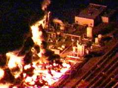
This is a picture showing the spectacular fire at the SEGS II solar electric system at Daggett, CA. This is, if I have all the information right, an array of parabolic troughs made by LUZ. The fire is burning high temperature oil, Thermol, used to transport heat from the troughs to a thermal storage tank.
The system was built in 1984 and is the second of a series of SEGS, solar electric generation systems. I understand that, as with Solar II, the system uses the thermal storage to even out power variations and provide time shifting of the power delivered to the grid.
As reported by dsg who personally was there and reported on "alt.energy.homepower" on 990525.
> Hi:
> Stopped at SEGS I and II facility. Took tour. Talked to chief engineer about fire. Fire was caused by NATURAL GAS problem in power block;
> completely -UNRELATED to the solar troughs.
> The first fire years ago was due to over heating the oil (human error) and was caused by trough tube leak..
> -dsg<rmv_soltherm@chatlink.com>
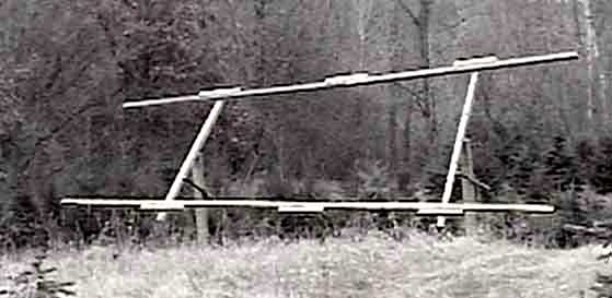
Type 2 revision B Heliostat Mirror Frame.
This is a picture showing the beginnings of the new wooden frame. This frame uses 2 satellite dish linear actuators to effect frame tilting. In this revision 2 actuators are used to independently adjust the 2 ends of the frame. The actuator driver has the ability to operate 4 separate actuators. In addition 2 more actuators are used to rotate and focus the mirrors.
The frame supporting piers are tilted by about 15°s to the south. This allows the frame to be tilted, in an emergency, below the horizon. This guarantees that the reflected light doesn't have the ability to cause a fire.
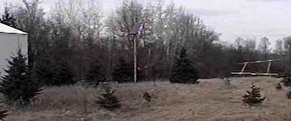
Big picture of where I am building the third Heliostat prototype.
This picture shows the orientation and placement of the pole barn, Solarex PV panel, and Heliostat frame.
My full scale demo system sends light about 170 ft to the north side of a metal pole barn at a height of 10 ft above the center of the heliostat array. This heliostat is located approximately -91°s west and 45.5°s north. The heliostat array is offset to the east by 30 ft because of the trees. This location is not ideal but is typical of the compromises needed in real world applications. The simple receiver is about 4 ft x 9.5 ft with an effective concentration factor of about 5.3 to 1.
                        North
                      [[[[]]]]Heliostats
     Trees     <--30ft-->/
               ^        /
       Trees   |       /
               |      /
      Trees    |   170ft
             167ft  /
West    Trees  |   /                East
               |  /
        Trees  | /
               |/
               v
              [*]Receiver
      --------------------        -
     |     Pole Barn      |      | |
     |                    |       -
                        South   PV Panel
A 1.5 in. PVC conduit buried in a 170 ft. shallow trench runs from the pole barn to the mirror array. This conduit carries the power and communication cables. A small, 10 Amp hour, 12 Volt deep cycle battery is located near the heliostats. This battery provides the transient high currents required by the satellite actuators when they are activated. The power cables are used to charge the battery. The positive wire is inside the conduit and the negative bare wire is laid outside the conduit and serves as a ground. The negative wire in the communications cable is also connected to the negative terminal of the heliostat battery and the ground wire.
If the power grid is available a conventional 12 Volt battery charger would be used to supply power to the system. I still recommend the use of the small, 10 Amp hour, battery even if the grid is available. The battery is inexpensive and enables the use of a very small charger. This could cost about $40us plus a $30us battery. Of course the system will still run on the battery when the power from the grid goes down.
If a power supply large enough to operate all the actuators without the battery is used it would need to be able to source over 30 Amps of current. This could cost about $200us. This doesn't make sense to me. The small charger and battery is cheaper and performs better.
I have a Solarex MSX60 PV panel, about $360 us, and a Solarex temperature controlled shunt regulator, about $60 us, that charges several lead acid deep cycle batteries that are in my pole barn. The battery bank inside the barn is connected to the heliostat battery through the power cables in the conduit. This PV panel is very expensive compared to a power grid based charger. Unfortunately it is simply required when installing the heliostat array in an off grid situation.
I think that the basic requirement for the PV panel would be about a 20 Watt unit. This would cost about $200 us. Of course all of these off grid systems need to have a very low powered computer if the lowest cost PV panel is used. Of course if the heliostat array is used to generate electricity much power would be available.
Hey, the heliostat tracks the sun. If the PV panel is mounted on the heliostat array in such a way as to partially track the sun the total power obtained from a PV panel is increased and the tracking is for free. I suspect that a 10 Watt PV panel would be sufficient, (I will work on this this summer.) What could be better?
I don't have a wind generator in my power mix yet. I plan to try a small AIR 303 this summer to supplement the PV panel. This wind generator costs about $550 us. This wind generator is rate at 300 Watts maximum. I understand that it will deliver about 30 watts average at my site. In general, I suspect that the PV panel is a better match for the my heliostat arrays since I mostly need to move the heliostat only when the sun is out. My computer can stop the movement of the actuators when the sun is not out thus alleviating power waste when not needed.
The conduit is brought up to a sealed plastic outdoor electrical junction box. This box is mounted to one of the piers. The satellite actuator driver board is mounted in this box. I normally have my control computer inside the pole barn. I can also have a small computer mounted in the box for testing of the heliostats.
The location of the control computer is a decision that the customer needs to make. If the computer is inside the home then access to the logging data is easier. If the computer is at the heliostat then the trench and conduit is not needed.