I'm a member of a group called the "Kansas City Space Pirates". While investigating how to reflect sunlight to a space elevator or climber I found a special class of heliostat tracking mounts I've been calling the "Arc Heliostat".
The "Arc" in the name mean the individual mirrors are arranged in an arc segments of a circle around the receiver. ( Does anybody know what the proper name of this is, or should be? )
We needed a few special requirements for this.
1. The climber would travel essentially on a vertical path. The climber would have a "solar panel" mounted up side down to receive light from an array of heliostats on the ground reflecting light, essentially, upward to it.
2. There needed to be at least 20 mirrors in the heliostat array.
3. The heliostat array would need to react rapidly and follow the vertical movements of the climbers motion.
4. These motions need to be well coordinated and preferably not require complex mathematical calculations to facilitate the rapid motions.
5. Though not strictly a requirement, it would be nice if the individual heliostats could be mounted on movable carts as in a train so they can be quickly moved into position when our turn begins in the contest.
I investigated the patent records and found these examples, (there may be more):
There are several requirements for a system to be called an Arc Heliostat: 1. The individual heliostats must be, generally, of the "Hinge" type. I.e. the main axis is the "Tilt Axis" or ALTitude, it is horizontal and normal to a vertical line through the receiver. The individual Tilt Axes are arranged in a circular arc around the receiver at a constant radius from the receiver. However, unlike a true "Hinge" which rotates the hinge in AZimuth, the hinges are fixed in orientation at their stations around the circle. The maximal motion for all conceivable locations of the sun and receiver along the vertical line in Tilt or ALTitude is �180� although -22.5� to +67.5� may be more appropriate. 2. The secondary axis, the "Rotate Axis", rotates about an axis perpendicular to the main circular Tilt or ALTitude Axis. The maximal motion for all conceivable locations of the sun and receiver along the vertical line in Rotation is �90�. 3. The mirror mounts are arranged in a circle perpendicular to the vertical line through the receiver. There may be multiple sets of circular mirror arrays. However, each set has a different Tilt orientation.
There are several distinct advantages to an Arc Heliostat:
1. All mirrors in a circular set have the same Tilt or ALTitude angle. This angle
is defined by the average of the Sun's ALTitude angle and the receiver's
ALTitude angle.
((Sun's ALTitude) + (receiver's ALTitude)) / 2
2. The rotate angle, for individual mirrors, have a simple linear angular
relationship to each other. This angle is defined by the mirror station or
position around the circle and the Cosine of Sun's ALTitude.
A. Station 0, The Master station, is the mirror which is opposite
the Sun's AZimuth angle and is always defined as 0�s.
B. Stations �n, (up to �180�s) have an angle of
COS(Sun's ALTitude)* n/2.
3. If several receiver positions along the vertical line are desired
to be alternately heated, as in some refrigeration systems, it's a
simple task to just collectively change the tilt angle of the mirrors
in a circular set to rapidly change the target position.
explanation
Explanation of how it works
Basics:
All single mirror heliostats must orientate a mirror to an angle that is normal to the bisector between the angles of the Sun and the receiver. Since these applications are 3D in nature motions are in 2 axes mutually perpendicular to each other. All heliostat mounts have these 2 axes.
There are 2 types of motions:
1. Direct tracking motion or Full Speed Motion.
2. Bisector tracking motion or Half Speed Motion.
In many heliostat mounts, (AZimuth/ALTitude), the ratio of full and half speed motions are mixed up with each other in the 2 axes. Furthermore, the ratios of full and half speed motions continuously change throughout the day in each axis. This is why many heliostat designs require mathematical calculations, read that as a computer, to control these motions.
However, there are 2 basic heliostat mount types that can operate without these complex calculations.
1. With the "Receiver Axis" heliostat mount ( and the similar but trivial "Solar Axis" heliostat mount )
one axis is aligned with the receiver and is rotated in such a way
the secondary Tilt Axis aligns perpendicular with an arc between the Sun and the receiver.
The major advantage of this design is the 2 motions are divorced from each other in the 2 axes.
The Tilt Axis contains all of the Half Speed Motion and
the Rotate Axis contains all of the Full Speed Motion.
2. The second is the Arc Heliostat array mount described here.
simplest
Simplest Arc Heliostat:
With heliostats mounted on circular tracks.
The simplest explanation is based on several of the patents that have mirrors mounted on tracked cars as in a train. The tracks are circular and arranged around the central axis. Each car has a main Tilt horizontal Axis mounted as a hinge in line with the tracks. The secondary Rotate Axis angle is changed and is defined by the individual station position around the track and the Sun's ALTitude. Since the rotate angle changes linearly between station 0 and the station on the opposite side of the circle, relatively simple cable and pulley mechanisms can be used at each station.
The Tilt Axis linkage between the cars can be as simple as automotive drive shafts with constant velocity U-joints, a pair of conventional cross U-joints, coupled together. This drive shaft can be driven by the middle, station 0, car and communicates the same Tilt Angle to all the cars. The Rotate Angle is manually adjusted and then fixed in place.
(I'm not so sure, think this is wrong, I'll need to investigate this statement!!!)
To operate, the cars are moved around the track using a single axis solar tracker until the station 0 car is opposite the Sun's AZimuth angle. The Tilt Axis is tracked using a single axis solar tracker mounted on a bisector angle mechanism such as used on the "Receiver Axis" heliostat tracking mounts. See:
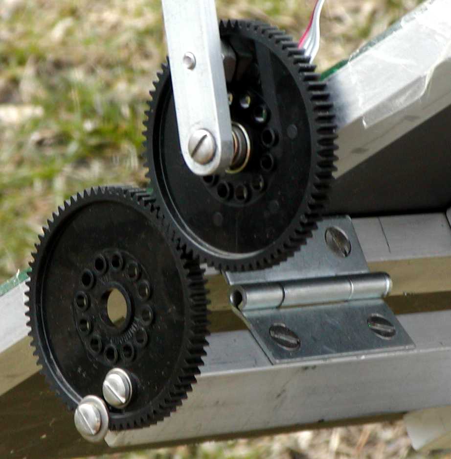 2 to 1 bisector mechanism
Another simple single axis solar tracker is used to measure the Sun's ALTitude and drive the cable rotation mechanism.
complex
A bit more Complex Arc Heliostat:
Similar to the Simple Arc Heliostat except the rails and cars are not used. The tilt axis can still be made using the drive shaft and U-joint structure but it's fixed in place around the central vertical line. The tilt control can be put in at any, or multiple, locations around the circle.
The tracker for this would, most likely, be a computer to calculate the Sun's position in ALTitude and AZimuth. The Sun's AZimuth defines an exact pseudo-mirror station around the circle. The computer then calculates the real rotation angle of each mirror in the mirror sets. Rotation is probably done using stepper motors. Once per day, probably at night, the rotation angle can be mechanically reset in case step errors have occurred.
excel
I have an Excel spreadsheet that can illustrate the simple relationships of the elements in the system.
http://www.redrok.com/archeliostat1.xls
Note! This is specifically for a the space elevator project but the concept is the same for a conventional heliostat array, except the receivers will not be moving around as with the space elevator.
 Go back to Red Rock Energy.