
 Go back to Red Rock Energy.
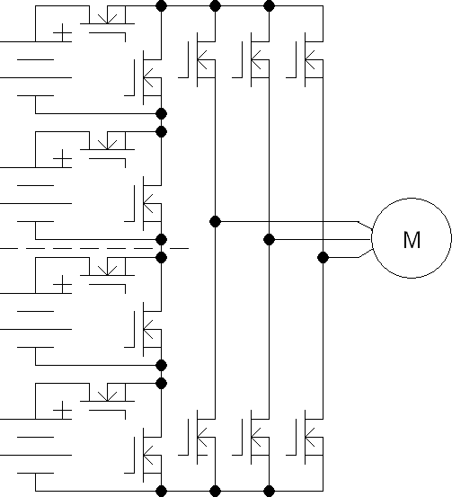
Overall schematic of the BatPack EV power controller.
<Bryan Foster> has persuaded me to revisit the BatPack controller. There have been great strides in the cost and performance of power MOSFETs in the years since I made my first controller. Bryan wants me to redo the cost calculations and further describe the operation of the circuits.
I will keep my old page as the second half of this page so one can see how I got to this stage in the design.
Back in the summer of 1997 or so it didn't seem to us, Virgil Vinz and me, there was not a lot of interest in high power EV controllers. Apart from my Hyundai, his Avenger kit car, and an electric lawn tractor we didn't pursue this much further.
We determined a patent for the basic concept couldn't be obtained as there was prior art in the form of a mechanical switch patented in about 1969 that operated in the same way. OK, there were elements that could have been patented such as:
1. Even discharge of BatPacks with differing capacities.
2. Intermingling BatPacks of differing voltages, battery types, and capacities.
3. Dynamic regenerative breaking.
4. Even charging methods by modulating the bypass switches.
We still couldn't justify a patent for these things as the costs for defending the patent, at least $250,000us would make no sense in the absence of sizable sales. So we just didn't do it.
Anyway, we went to other pursuits. Solar trackers for me and building CNC machine tools for Virgil. This was probably a good choice for both of us.
The advantages of the BatPack controller are still relevant today. The cost of MOSFETs in this power class has come down drastically. The BatPack advantage where lower breakdown MOSFETs were much cheaper than high voltage types has been largely negated, although still somewhat true. However, the other advantages are still valid.
The second schematic shows the simple addition to drive a 3 phase motor.
I will use the 125 volt controller as a reference and calculate both a 250 Volt switcher and a 250 Volt BatPack. I will be using generalities in these calculation. I think they are close to reality. If in the future there are improvements in the cost and performance of MOSFETs the equations could be adjusted for those conditions.
One of the most important requirements when selecting transistors for power controllers. Is the total current carrying capacity. The current carrying capacity of a transistor is primarily inversely proportional to the on resistance. There is a secondary limiting factor caused by the current carrying capacity of the internal conductors of the transistors.
| 125 Volt switcher | 250 Volt switcher | 250 Volt BatPack (6 36V Packs) | 125 Volt BatPack (5 24V Packs) | 72 Volt BatPack (8 8V Packs) | |
| MOSFET | IRFB4332PBF $2.60us | IXFK80N50P $14.72us | IRFB3006GPBF $2.97us | IRLB3813PBF $1.54us | IRLB3813PBF $1.54us |
| Break down voltage Drain to Source. | 250 Volts | 500 Volts | 60 Volts | 30 Volts | 30 Volts |
| Relative on resistance of each MOSFET. | .029 Ohm | .065 Ohm | .0025 Ohm | .0020 Ohm | .0020 Ohm |
| Current capacity of each transistor. | 60 Amp | 80 Amp | 195 Amp | 260 Amp | 260 Amp |
| Relative total MOSFET Costs | $13.00 = (250A / 60A) or 5 * $2.60us | $103.40 = (500A / 80A) or 7 * $14.72us | $17.82 = (250A / 195A) or 2 * 6 * $2.97us | $7.70 = (250A / 260A) or 1 * 5 * $1.54us | $12.32 = (250A / 260A) or 1 * 8 * $1.54us |
It's clear that MOSFET cost is no longer the prime factor in the design.
Prudent design would make it easy to double or even quadruple the number of MOSFETs connected in parallel to reduce the ON resistance of the switches. Heating effects in the MOSFETs in a BatPack switch is mostly due to I^2R losses in the MOSFETs and interconnections. For example:
1 MOSFET  = 1   heating unit,  1    heating unit  per MOSFET
2 MOSFETs = 1/2 heating unit,  1/4  heating units per MOSFET
4 MOSFETs = 1/4 heating unit,  1/16 heating units per MOSFET
 Bill Darden's Battery FAQ page.
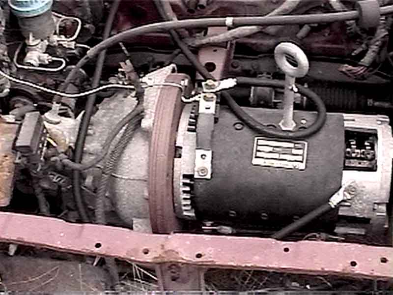
Traction motor in my Hyundai EV.
This is a picture of the engine compartment of my Hyundai EV. I chose the Hyundai Excel GL as the donor car because it is easy to fine late models with blown engines just out of warranty. So far I have purchases 2 for $300 a peace with less than 60000 miles.
I removed the original 450 lb. IC engine and replaced it with an Advanced DC Motors 9.1" FB-4003 20 hp series wound motor. I built the adapter plate from stacking 5 layers of 1/4" steel disks. The centers were flame cut to shape and welded together.
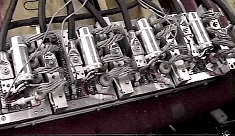
Prototype quad section BatPack EV power controller.
This is my prototype of the BatPack controller. It is composed of 4 BatPack switches. There are 4 sets of battery connections going to 4 sets of batteries. In this case there are two 24 Volt BatPacks and 2 36 Volt BatPacks. The total voltage of all BatPacks is 120 Volts.
I got into this project when it was pointed out to me that there was a need for really powerful EV power controllers that ran from 250 Volt batteries. Some of the racers wanted to a motor system that delivered about 250 hp for about 10 seconds. The most efficient way to do this was with battery voltages double that currently available. The battery voltage was limited by the availability of suitable high voltage power MOSFETs.
I made a leap of logic when I discovered that the on resistance of MOSFETs increased with the BVds to the power of 2.8. This factor approximately was true for all venders. Ok, so with the use of 500 Volt MOSFET used in the 250 Volt switcher vs. the 250 Volt MOSFETs used in the 125 Volt switching controller I would need about 7 times as many transistors connected in parallel. But wait, the current delivered to the motor in the 250 Volt configuration is about double that of the 125 Volt controller so I need to double the number of transistors again to 14 times. It gets worse, These transistors cost at least 1.5 times as much as the ones used in the lower voltage controller. Can it get even worse? Yes, Power is dissipated in the transistor during the switching times and is greater in the high voltage circuit than in the lower voltage circuit. I don't have a simple factor for this but the other factors are bad enough.
I knew I would have to take a new approach. But what? How could I take advantage of the exponential reduction of on resistance with lower voltage transistors. Can I break the batteries into smaller units. "AHA!" Yes I can.
If I break the battery into packs of 18 cells, (3 12 V units). Six of these packs can be connected in series to obtain the 250 Volts. Each pack is only 41.4 Volts, (18 * 2.3 volts). I can use 60 volt MOSFETs in this circuit.
I will use the 125 volt controller as a reference and calculate both a 250 Volt switcher and a 250 Volt BatPack. I will be using generalities in these calculation. I think they are close to reality. If in the future there are improvements in the cost and performance of MOSFETs the equations could be adjusted for those conditions.
One of the most important requirements when selecting transistors for power controllers. Is the total current carrying capacity. The current carrying capacity of a transistor is primarily inversely proportional to the on resistance. There is a secondary limiting factor caused by the current carrying capacity of the internal conductors of the transistors.
The relative cost of the transistors is approximately the product of breakdown voltage and current capacity.
| 125 Volt switcher | 250 Volt switcher | 250 Volt BatPack | |
| Break down voltage Drain to Source. | 250 Volts | 500 Volts | 60 Volts |
| Relative on resistance of each MOSFET. | 1 Ohm | 7 Ohm | .018 Ohm |
| Relative current capacity of each transistor. | 1 Amp | .14 Amp | 54 Amp |
| Relative quantities of transistors based on current capacity. | 4 = 1 Ohm * 2 voltage units * 2 current units | 14 = 7 Ohm * 2 current units | .22 = .018 Ohm * 2 current units * 6 Packs |
| Relative total Cost | $1000 = 250 * 1 * 4 | $980 = 500 * .14 * 14 | $712 = 60 * 54 * .22 |
I have investigated the use of power IGBTs for use in my BatPack switches. These devices are particularly useful in high voltage high power switching applications. Some of the newer power controllers use these devices.
Unfortunately these devices inherently have a forward voltage drop of about 3 Volts no mater what the forward current This voltage drop is not usually a problem when dealing with a single transistor at high voltages. The 3 volt drop is acceptable when and not much different from power MOSFETs when used at the same voltages. In the BatPack controller where multiple switches are in series the total power dissipation becomes excessive during cruising EV conditions.
To be fair, IGBTs are superior in operation to power MOSFETs in high voltage applications because of the regenerative feedback in the structure of the device.
The operation of an IGBT is similar to that of a Darlington transistor pair where one transistor is used to drive another. The input transistor gets it's emitter output current from the collector of the output transistor. Darlington transistors have a characteristically high collector to emitter voltage drop because the emitter drive current of the output is derived from its own collector. As the collector voltage approaches the voltage of 1 diode drop it's emitter current drops to nothing. In a similar manner the IGBT output transistor derives it's base current from an input MOSFET transistor connected between it's collector and base.
One characteristic of all Darlington type circuits is the ability to operate successfully in high over current conditions. The inherent current feedback makes the output transistor conduct even harder in over current with only a small increase in collector to emitter voltage. Conversely the power MOSFET voltage drop is determined by the drain to source on resistance is a linear function of current. In similar over current conditions the voltage drop of the MOSFET will be much higher than the IGBT. This ability of the IGBT to successfully operate for a short time in over current conditions protects it from excessive heating that would destroy the MOSFET. On the other hand the MOSFET has a much lower voltage drop than the IGBT' 3 volt drop during the times of normal lower current operation. In an EV the IGBT transistor needs more heat sink than does a similar MOSFET. It's tradeoffs everywhere!

Overall schematic of the BatPack EV power controller.
The BatPack operates in a completely different manner from the common type of EV pulse width modulating, PWM, power controller. My BatPack power controller operates by switching smaller subset packs of the total battery available in the car. These packs are switched either in series with the rest of the packs or out of the circuit. In my implementation there can be up to 6 steps of voltage from 0 to max. The number of steps needed is determined by the amount of acceleration requested by the operator.
The controller adds or subtracts packs to maintain the required average number of packs in series. The determination of whether to add, subtract, or maintain the current number of packs is done at the rate of 100 times decisions per second.
| 1. | If it is determined that a pack is to be added to the string the controller checks the voltage of all the packs. Which ever pack has the maximum voltage is the one that will be added to the string. |
| 2. | If it is determined that a pack is to be subtracted from the string the controller checks the voltage of all the packs. Which ever pack has the minimum voltage is the one that will be removed from the string. |
| 3. | Of course if no change in the number of packs is required then keep the status quo. |
You might ask why I check all the packs when looking for the maximum or minimum voltage pack? Won't some of the packs be connected to the string while others are disconnected? Will the determination of which pack status is to be changed be affected the current status?
The answer is no. When the controller is attempting to add a pack to the string it will be looking for the pack that is currently the highest voltage. This will not be any of the packs that are currently connected to the string as they will be under load and consequently be low in voltage.
Conversely, when the controller is attempting to remove a pack from the string it will be looking for the pack that is currently the lowest voltage. This will not be any of the packs that are currently disconnected from the string as they will not be under load and consequently be high in voltage.
This process of adding the strongest and removing the weakest pack from the string has the effect of loading all the packs in a manner that the charge will be evenly removed from all packs. Note that some packs may have lower total charged capacity than others.
Once the concept of the BatPack was understood I found that there are many useful and unique advantages over switching power controllers.
| 1. | The BatPack switches at a low rate. I have used a transition rate of 100 Hz. The conventional 20 KHz switchers have a transition rate of 40 KHz. Furthermore the transition voltage is only the voltage of a single battery pack not the full voltage of 250 volts. |
| 2. | An even consumption of the capacity in each battery pack.
In a conventional switching controller with all cells in a series string the total current in all cells is the same. This has the effect of approximately removing the same charge from all cells. Unfortunately this may completely discharge some weaker cells before the stronger cells are depleted. Of course the controller is not allowed to continue discharging the battery when any cell is discharged beyond a certain point. This leaves some unrecoverable charge in the batteries system. The BatPack, on the other hand, will remove more charge from the packs before any individual cells have become depleted even though some cells are weak. Real world batteries don't each have exactly the same amount of charge. After the packs have had some recording time on them, the batteries can be rearranged so all of the weaker or all of the stronger cells are in the same packs. This has the effect of being able to remove even more total charge from the real world battery system compared to the conventional system. |
| 3. | The BatPacks don't all need to be the same nominal voltage. They can be almost any nominal voltage. My controller is programmed with the nominal voltage of each BatPack. The controller determines the strength or weakness of a pack by dividing the actual voltage by the nominal voltage. It has been determined that with a sufficiently high transition switching rate one isn't aware of the fact that the BatPacks are not the same size.
In addition, if a microcomputer is used in the BatPack controller, the controller can determine the nominal voltage automatically. This is useful if the normal BatPack battery array is replaced by a high performance pack with higher nominal pack voltages. This high performance pack may be used for drag racing applications. After installing the BatPack array the computer is reset. The computer measures the open circuit battery voltage and temperature. From this information and a nominal pack voltage is calculated. |
| 4. | If any of the BatPack switches or battery packs become damaged the EV can still operate by running on the remaining components of the system. Try that with conventional switching controllers which will leave you dead in the water. |
| 5. | If the computer controller becomes damaged the car can still be moved by manually operating the BatPack switches. This is the way I have sometimes moved the car now. A single BatPack, at 36 Volts, can be directly connected to the Advanced motor and the motor will not be damaged due to over revving even if the clutch is in and freely turning. Ok, it is spinning really fast but not too fast. The car can now be driven many miles at speeds up to 40 miles per hour with no controller present at all. |
| 6. | The controller has a microcomputer as the heart of the system. Computers now have the ability to save a ton of data in memory. This data is used to improve the performance of the car by calculating which gear to be in and shifted at what speeds. Driving and shifting an EV are decidedly different from the conventional IC car. |
1. 10Hz switch rate is acceptable on a car with its
   large motor. The battlebots worked better at 100Hz.
2. The BatPack concept works well and uses low voltage
   MOSFETs which are lower in cost.
3. The concept of matching batteries of similar
   capacities in packs allows for more efficient
   extraction of energy from the whole system worked
   well.
4. The concept of using pack voltage to choose which
   BatPack is added and subtracted from the string
   worked well. This strategy keeps all packs at a
   similar charge capacity percentage even though they
   have different capacities and voltages.
5. The BatPack, in my mind, is clearly superior to the
   standard high switching rate PWM controllers.

Future work:
1. A micro needs to be on each BatPack to measure pack
   voltage, control the MOSFET switch, and communicate
   with the main controller.
2. A second set of BatPack switches can be used to
   implement regenerative breaking. The regeneration
   operates in a similar way to driving but switches
   the weaker packs in series and removes the stronger
   ones.

Much work needs to be done to make a finished circuit.
It's been about 10 years so even better and cheaper
MOSFETs are available today.

Are you interested in doing the hard work to help in
the circuit design for a new round of BatPack
controllers?
EV discussion List Photo Album.