SolarTracker Assembly
Introduction:
The Tracker PC board uses mostly surface mount parts. These components are difficult to assemble if you don’t have the required skills and equipment. I am presenting these instructions for those who wish to attempt this task.
The
assembly should be done in the specific order outlined to minimize the risk of
damage to the circuits in case there are solder shorts or misplaced components.
Caution:
The components in this circuit are susceptible to damage through static discharges. Use normal static discharge prevention techniques such as a grounded workbench, soldering iron, and personal grounding wrist straps.
Assembly Tools:
1.
A
low wattage temperature controlled soldering iron that can be set to 650F.
2.
Solder
paste. I use Multicore RMA mild activation rosin based solder paste in a 25 mG
syringe (RM10). This paste contains 2% silver for excellent wetting action.
Digikey part number SN62RM10.
3.
Small
diameter wire solder. I use Kester RMA mild activation rosin based “37/63” solder
in .020” wire size. Digikey part number KE1201.
4.
Toothpicks
to apply the solder paste.
5.
Metal
tweezers for manipulating the tiny components.
6.
Magnifiers
or high magnification reading glasses. I use 3.5 or 4 diopter glasses.
7.
Solvents
to clean the solder flux. I use Sinosol, available at building centers.
8.
A
digital multimeter with sharp pointed probes for measuring resistance and
voltage.
9.
A
current limited 12 volt power supply. Set to about .25 amps.
10. A bright light source for
testing the tracker operation.
Assembly:
Whenever
power is applied to the board it is
wise to put a finger on the LM317LM to feel how warm it is getting. Any
noticeable increase in temperature is an indication that the circuit should be
immediately disconnected.
1.
Apply
all resisters, capacitors and transistors.
2.
Add
the connector to the backside of the board. The connector must be soldered on
both sides of the board as my board manufacturer neglected to drill and plate
these 4 holes. Do not solder the two center pins on the topside at this time.
This will be soldered at a later time.
3.
Measure
the installed resistance of the components.
4.
Check
for shorts to ground at all component nodes.
5.
Add
the LM317LM making sure of the orientation of pin 1. Refer to the picture. Or
an enlarges version at: http://www.redrok.com/images/ledshex3.jpg

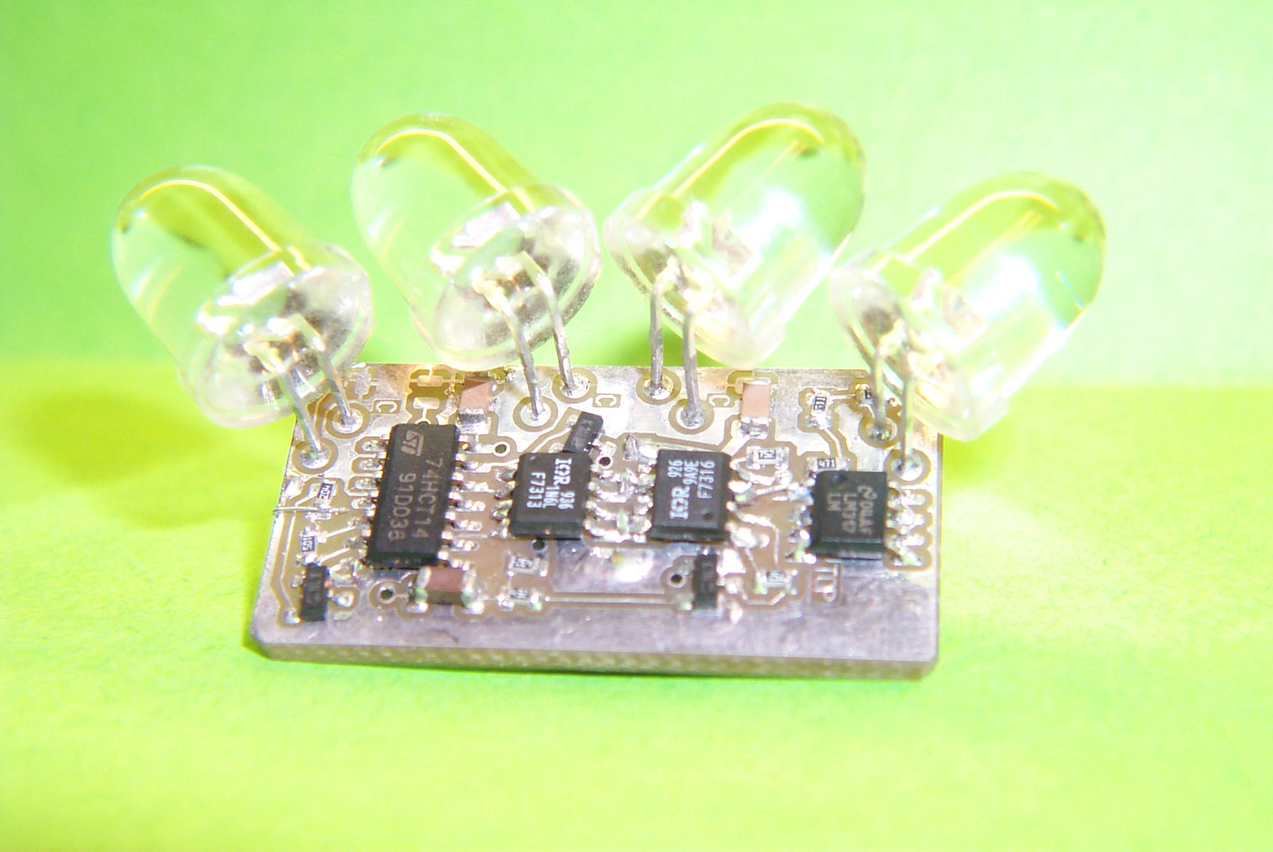
6.
Apply
12 volts to the circuit through the connector.
7.
Observe
that the LM317LM is regulating to about 5 volts. And that there is about 1.4
volts on the four outer LED pad.
8.
Add
the 74HCT14.
9.
Observe
5 volts on pin 14 and 0 volts on pin 7.
10. Observe pin 8 to see the oscillator output. This is mostly at 5
volts with short drops to 0 volts.
11. Add the 4 LEDs to the board. Leave the LEDs in the fanned out
position as indicated by the position of the mounting pads. This gives the
outer LEDs an additional 15 degrees angle.
12. Observe that the voltage on
the input to pins 1 and 3 change voltage to between about 0 volts and 3volts
when the LEDs are illuminated with a strong light source. Move the tracker
about to see these voltages are changing.
13. Observe the voltage on the IRF7313 pads 1 and 3. These should be
either 0 volts or 5 volts depending on orientation of the light source. There
should never be 5 volts on the pins at the same time. (After final adjustment
of the LED position it’s possible for them both to have 5 volts but not for
now.)
14. Observe the voltage on the IRF7316 pads 1 and 3. These should be
mostly at 12 volts with intermittent drops to about 4 volts depending on the
orientation of the light source. For any orientation only on of the pins will
be dropping to the lower voltage.
15. Add the IRF7313 and IRF7316 MOSFETs. This will now solder the
center two pins of the connector.
16. Make sure there are no shorts to ground or between the center
connector pins.
17. Apply power and observe that the voltages on the center pins of
the connector are pulsing dependent on the orientation of the light switch. A
test circuit with a pair of small red and green LEDs connected back to back and
in series with a 470 ohm resister on the center pins of the connector will
indicate which way the bridge is driving. The color indicates east or west
movement dependent on the orientation of the light source.
18. Add the 1N5359 24 volt 5 watt zener diode between the positive and
ground foils on the topside of the board. This zener has its leads cut and
formed to allow this surface mount soldering technique. The body of the Zener
lies between the LM317LM and the IRF7316.
19. Connect to a linear actuator and observe the operation of the
actuator. The linear actuator must have limit switches, properly adjusted, with
reversing diodes across the switches. This protects the driver from excessive
current should the actuator run into the end of travel and stall.