
Click the Picture.
a1assembly
LED5a1 Solar Tracker Assembly
This discription is preliminary and is currently being edited. This page was coppied from the LED3X assembly page. Bear with me until I get it done.
a1introduction Features: Caution: The LED3Xc1 Tracker PC board uses through hole parts. These components are easier to assemble than the surface mount parts on the previous LED3 tracker.
The assembly should be done in the specific order outlined to minimize the risk of damage to the circuits in case there are solder shorts or misplaced components.
Caution: Assembly Tools:
1. A low wattage temperature controlled soldering iron that can be set to 700F.
2. Small diameter wire solder. I use Kester RMA mild activation rosin based 37/63 solder in .014" wire size.
3. Metal tweezers for manipulating the tiny components.
4. Magnifiers or high magnification reading glasses. I use 3.5 or 4 diopter reading glasses.
5. Solvents to clean the solder flux. I use Acetone, available at building centers. Cleaning should be done in a well ventilated area. Acetone is Flammable so be careful. You can also use "Heat" automotive gas line antifreeze. Dont use the newer isopropol version. Use the older methynol based "Heat" in the yellow container.
6. A digital multi meter with sharp pointed probes for measuring resistance and voltage.
7. A current limited power supply, set to about .25 amps. To further limit the current put a 500 ohm 1/2 watt resistor in series with the output. This power supply should be adjustable from at least 0 volts to about 16 volts to adequately perform the tests.
8. A bright light source for testing the tracker operation.
a15vschematic a112vschematic a1assembly Generally parts are put in the top side of the board and soldered on the bottom. This is a simple board with relatively few parts. For this reason it is probably best to install one part at a time. Assemble in the order of shortest to tallest.
The boards can be used in a number of ways, single or dual axis, and with a variety of transistors. Also the connector can be put on either side of the board. These instructions are for the 12V single axis variety. 5V options will be be noted where aplicable.
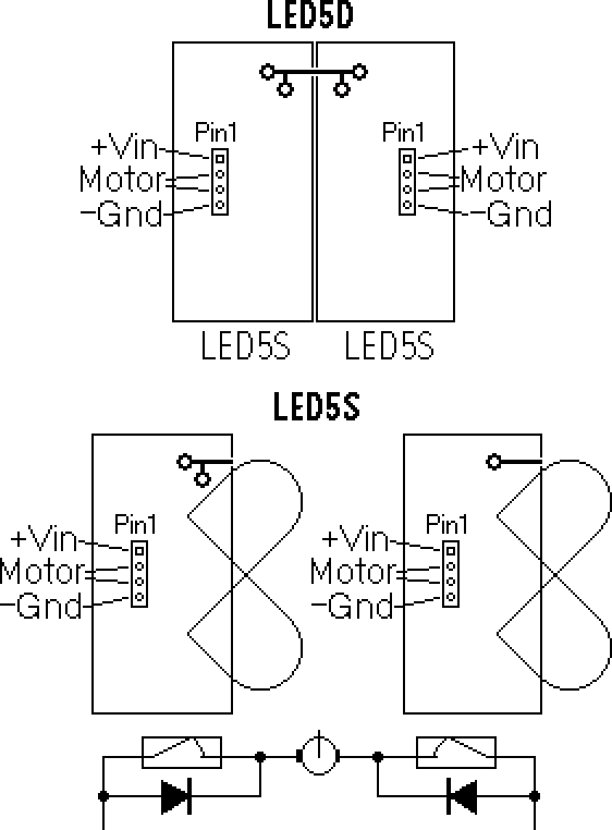
There are left and right flavors of the single axis boards. This is because they are cut from the dual axis board, right down the center. It is best that they are all oriented the same way, it would be confusing if they weren't. I intend that they be oriented with the connector on the left, LED sensors on the right, and +Vin at the top. The +Vin power buss is at the top, the dark line in the diagram.
The most important test to perform is the Ohmmeter test. This board is laidout in such a way that most of the circuit traces can't short out to each other, rather, these shorts will be to ground. Shorts can be caused by a variety of things. The most common is a solder bridge but shorts could come from the PC board manufacturer also. The Ohmmeter test is easy to do. Just set the Ohmmeter to something like 20K Ohms with the - terminal connected to the ground plane. The + lead then tests all the circuit pins looking for zero ohms or shorts.
Don't worry if a higher value is read as this is most likely just the forward drop fo circut junctions. You can prove this by changing the Ohmmeter scale. If it is a junction the resistance value read will change. If it is a true resistance the value will be the same.
1. Mount the components in this order:
2. Install the connector. Note where pin1 is located, it's the square pad. I put a small red marker on pin1.
3. Do an Ohmmeter check to see if there are any shorts to ground and fix any.
4. Apply current limited power to CONN1, +5 volts or so between pin 1 + and pin 4 -, and a voltmeter between pins 2 ans 2. Shine light on the sensors. The voltage should vary and reverse when the light is moved.
5. Connect a motor between pins 2 and 3. Apply non current limited 13.8V, (5V for the 5V unit). Watch the motor turn and reverse when the light is moved.
6. Mount the tracker inside a weather dome. Use a #4 machine screw. Make sure there are no shorts. I use Jiff plastic peanut butter jars. They seal quite well.
7. Good luck.
Introduction:
The LED5a1 is designed to low powered gear motors. It comes in several variations. Single or dual axis and 5V or 12V.
1. 2 LED light sensor with center deadband.
2. In addition to the standard sensor position that "looks" off the side of the board the LEDs can be positioned to "look" up from the board.
3. Single or dual axis versions.
4. Simple all analog circuitry.
5. All analog circuitry.
6. Provission for external sensors in the dual axis version.
7. The board doesn't use a heat sink.
Electrical specifications for LED55Va1
Parameter
Operating
Absolute Maximum
Input Voltage (5 volt nominal)
3 to 8 Volts
-4 to 11 volts
Load Current
250 mAmps
800 mAmps for a few seconds
Electrical specifications for LED512Va1
Parameter
Operating
Absolute Maximum
Input Voltage (12 volt nominal)
3 to 16 Volts
-4 to 22 volts
Load Current
100 mAmps
800 mAmps for a few seconds
Size specifications for LED5S
Single axis tracker
Parameter
Dimension
Length of the PC Board
1.25"
Width of the PC Board
.65"
Total Width Including the LED Sensors
1.00"
Total Height Including the Vonnector
.80"
Size specifications for LED5D
Dual axis tracker
Parameter
Dimension
Length of the PC Board
1.25"
Width of the PC Board
1.30"
Total Height Including the LED Sensors and Connectors
1.90"
The above table is useful to determine the capabilities of the various versions.
The components in this circuit are susceptible to damage through static discharges. Use normal static discharge prevention techniques such as a grounded workbench, soldering iron, and personal grounding wrist straps. Also the large mounting hole is connected to the negative power terminal and should be the first point touched when handling the circuit until the connector is installed which can then be the first thing touched.
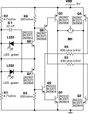
 LED5S5Va1 Schematic
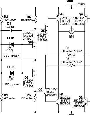
 LED5S12Va1 Schematic
a1layout
 LED5 Layout
"a1" Assembly Instructions for Single Axis Version:
   C1 .022uF
   R1  47K    1/8 watt resistor ( 10K 1/8W  for 5V)
   R2  47K    1/8 watt resistor ( 10K 1/8W  for 5V)
   R3 100K    1/8 watt resistor (100K 1/8W  for 5V)
   R4 100K    1/8 watt resistor (100K 1/8W  for 5V)
   R5  750    1/2 watt resistor ( 91  1/8W  for 5V)
   R6  750    1/2 watt resistor ( 91  1/8W  for 5V)
   Q1  NPN    2N2222A or BC337
   Q2  NPN    2N2222A or BC337
   Q5  NPN    2N2222A or BC337
   Q8  NPN    2N2222A or BC337
   Q3  PNP    2N2907A or BC237
   Q4  PNP    2N2907A or BC237
   Q6  PNP    2N2907A or BC237
   Q7  PNP    2N2907A or BC237
 LED1         Green LED
 LED2         Green LED
<redrok@redrok.com>