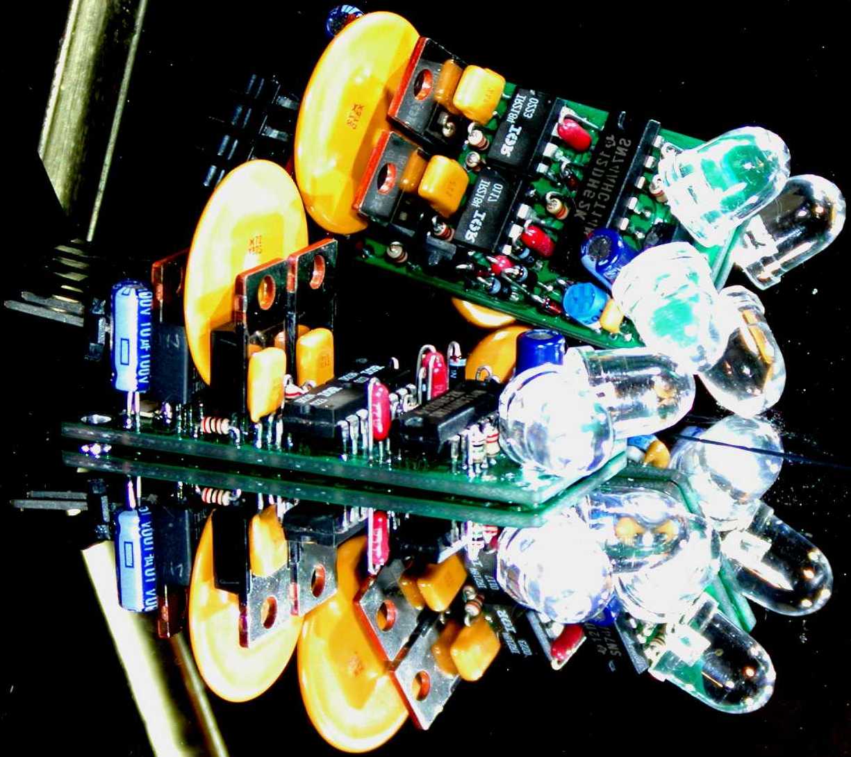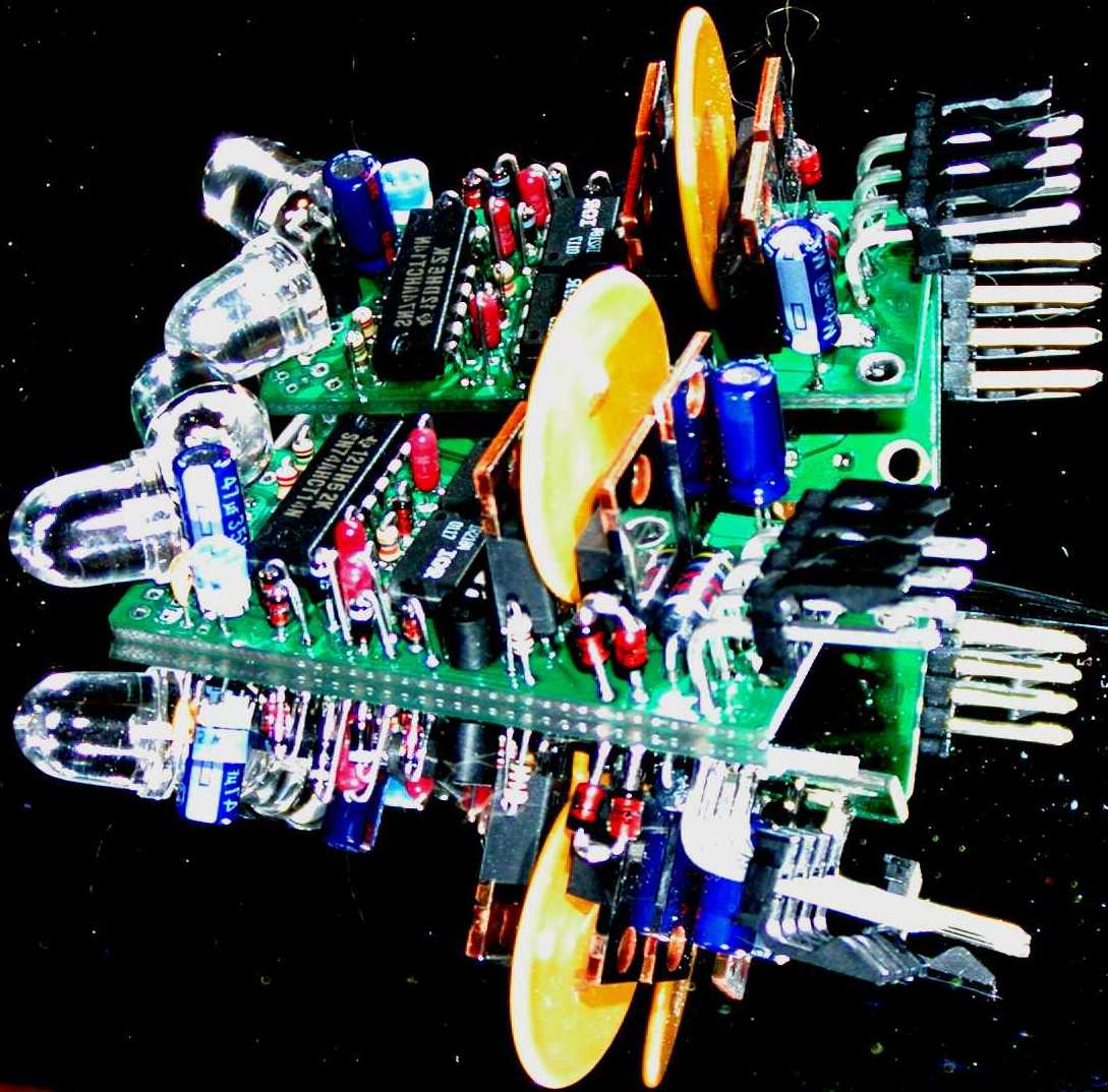
c1assembly
LED3Xc1 Solar Tracker Assembly
c1introduction The enhancements are: Other features: Caution: An experiment I have done was to drive a 12V automotive door window motor. This motor draws about 4 amps at 13.8V. I raised the voltage to 44V with a pulse width of about 1 second out of a cycle time of 18 seconds. The peak current into the motor is 55 amps! Everything remained reasonably cool. Cool huh!
The LED3Xc1 Tracker PC board uses through hole parts. These components are easier to assemble than the surface mount parts on the previous LED3 tracker.
The assembly should be done in the specific order outlined to minimize the risk of damage to the circuits in case there are solder shorts or misplaced components.
Caution: Assembly Tools:
1. A low wattage temperature controlled soldering iron that can be set to 700F.
2. Small diameter wire solder. I use Kester RMA mild activation rosin based 37/63 solder in .014" wire size.
3. Metal tweezers for manipulating the tiny components.
4. Magnifiers or high magnification reading glasses. I use 3.5 or 4 diopter reading glasses.
5. Solvents to clean the solder flux. I use Acetone, available at building centers. Cleaning should be done in a well ventilated area. Acetone is Flammable so be careful. You can also use "Heat" automotive gas line antifreeze. Dont use the newer isopropol version. Use the older methynol based "Heat" in the yellow container.
6. A digital multi meter with sharp pointed probes for measuring resistance and voltage.
7. A current limited power supply, set to about .25 amps. To further limit the current put a 500 ohm 1/2 watt resistor in series with the output. This power supply should be adjustable from at least 10 volts to about 18 volts to adequately perform the tests. It would be nice if the power supply can go as high as about 44 volts. However, make sure that you don't go any higher than 44 volts as this could damage the shunt protection zener diode D5. So be carefull. 8. A bright light source for testing the tracker operation.
c1schematic c1timing c1layout c1assembly When I say to "Tack Solder" this means to solder one lead of a component on the top side of the board. I have arranged all the components so one easily accesable lead is always on the end closest to the mounting hole. The components are small and light and one can't turn the board over unless tack soldered because they will fall out.
Lay the board flat on a table and insert the components so the leads are flush with the table. This make for a clean flat back side. I assemble and tack solder all small components on the top side before turning over to complete the soldering.
Note! Some components are not in the kit. These are for other options such as remote sensors, (CONN2, R11, R12) or direct drive controll, (CONN3, R10).
Also! There have been some substitutions of parts throughout the circuit. These were done mainly due to parts availability. OK, to be honest, I got some good deals on parts at ebay. I will comment about substitutions throughout the assembley instructions. These substitutions generally improve the circuit reliability.
The most important test to perform is the Ohmmeter test. This board is laidout in such a way that almost all circuit traces can't short out to each other, rather, these shorts will be to ground. Shorts can be caused by a variety of things. The most common is a solder bridge but shorts could come from the PC board manufacturer also. The Ohmmeter test is easy to do. Just set the Ohmmeter to something like 20K Ohms with the - terminal connected to the ground plane. The + lead then tests all the circuit pins looking for zero ohms or shorts.
Don't worry if a higher value is read as this is most likely just the forward drop fo circut junctions. You can prove this by changing the Ohmmeter scale. If it is a junction the resistance value read will change. If it is a true resistance the value will be the same.
1. Mount all horizontal components.
2. Tack solder the top side.
3. Mount all the vertical small components.
4. Tack solder the top side.
5. Q5 MPSA18 NPN Transistor. This can also be a BC337 or 2N3904. Note the different orientations if the MPSA18 or 2N3904 from the BC337 in the diagram.
6. LED1, LED2 Large 10mm Lumex Green clear cased LED.
7. CONN1
8. Turn over and solder all installed components.
9. Install the polyfuze and solder.
10. Do an Ohmmeter check to see if there are any shorts to ground and fix any.
11. Turn the potentiometer fully clockwise, apply current limited power to CONN1, +18 volts between pin 1 - and pin 4 +, and test for:
12. Install Q6 2SD667-D NPN Transistor and solder. A BC337 or 2N3904 can be used for 24V operation. Note!, the different package orientations. Note!, the 2SD667-D needs to be installed with the Collector and Base leads reversed.
13. Do an Ohmmeter check to see if there are any shorts to ground and fix any.
14. Turn the potentiometer fully clockwise, apply current limited power to CONN1, +18 volts between pin 1 - and pin 4 +, and test for:
15. U3 74AHCT14 hex Schmidt Trigger logic gate and solder
16. Do an Ohmmeter check to see if there are any shorts to ground and fix any.
17. Turn the potentiometer fully clockwise, apply current limited power to CONN1, +18 volts between pin 1 - and pin 4 +, and test for:
Note! U1 pin 2 is actually a pulsed signal that's about 10% 0 volts and 90% 5 volts at about 250 Hz.
Shine light onto LED1
18. U1 and U2 IR2184, Q1, Q2, Q3, Q4 and solder. 19. Do an Ohmmeter check to see if there are any shorts to ground and fix any.
20. Add C7 47uF 63V Capacitor for use with a 24V system. Observe the polarity. The stripe is ground. And solder. 21. Turn the potentiometer fully clockwise, apply current limited power to CONN1, +18 volts between pin 1 - and pin 4 +, and test for:
22. Apply full unlimited power to CONN1, +11 volts between pin 1 - and pin 4 +.
Be very carefull and make sure the current isn't more than a few 10s of mAs. The drivers can be damaged if the current is execssive due to a circuit short. Remove power imediatly if a fault is detected, especially if the drivers get warm. And test for:
Observe the operation of the indicator LED.
Drop the power supply voltage to less than about 10 volts. Adjust the power supply to find the point where the indicator LED operates. This should be around 10 volts with a histeresis of about .5 volts or so.
23. Connect a reversable DC motor with limit switches between CONN1 pins 2 and 3.
Observe the operation of the motor to see it go reverse, stop, and forward.
Observe the operation of the limit switches. Adjust the potentometer near counter-clockwise. 24. Mount the tracker inside a weather dome. Use a #4 machine screw. Make sure there are no shorts. I use Jiff plastic peanut butter jars. They seal quite well.
25. Good luck.
LED3Xc1 Solar Tracker Operating Instructions
Instalation: Be careful to avoid reflected light. One of my customers had quite a bit of problem with an adjacent white painted garage to the west. The solution was a small blocking shade to the west of the sensor.
Most use satellite dish actuators to move their mounts. The nice thing about satellite dish actuators is their slow speed of motion, low operating current, and the integral limit switches. Many of my customers build their own drives. The most successful have very high gear ratios. I recommend something about 100,000 to 1.
It's a REQUIREMENT to have limit switches in the motor circuit. When the tracker goes to park it drives the motor to the east and doesn't stop. The limit switch stops the movement. So you just have to have limit switches!!!
Top. Normal operation between limit switches. Sellect a diode or rectifier rated at the maximum motor current plus some margine. Also the voltage should be at leat 100V and preferably 200V.
Needles to say, the limit switch must operate before the mechanical limits are reached. If the mechanical stop is reached before the switch the motor can draw quite high currents and can destroy the solar tracker.
The power contacts are sized to accept a wire size up to 16 gauge. I usually use 24 gauge. High current motors may need a bit larger wire. However, even for high current motors large wire size is not required as the average current is less than an average of 3.75A.
The tracker was designed to be used in the northern hemisphere and park in the east. The components will then be up on the board. To use in the southern hemisphere flip it over with the components down. If the motor tracks in the wrong direction just flip the motor leads around.
If you want to park in the west, not recommended, flip the circuit opposite from above.
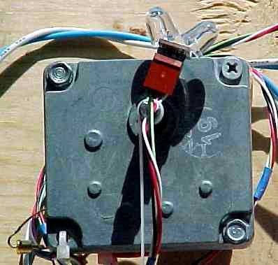
rowe This turns a bit fast without speed reduction but this was only a test besides it can be slowed down considerably with the duty cycle control. The diode that shows on the side of the motor is one of two across the limit switches on this gear motor. The motor was originally used on vending machines, and paper shredders, however it is no longer in their catalog.
Thanks for the pictures Patrick!
Note!, the LED3XS24Vc1 variant with external sensor, cable, and connectors costs $45us + s/h.
paulpakelson wolfgang
This project has been a bit of a struggle. We first tried to to use the LED5 low power solar tracker as Wolfgang was using high gear ratio motors rated at 100mA. However, during storms the high winds caused overloading and burned them out. Unfortunately the standard LED3X high power solar tracker would try to park at night, but there are no limit switches in the system which would cause the panels to turn all night, not good. The solution was to add the "no park" feature which works perfectly for him.
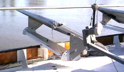
See how the constant tilt PV panels can rotate under the boat railings.
led3xc1mods
Introduction:
The LED3Xc1 is designed to drive satellite dish linear actuators. Actuators have built in limit switches. Revision "c1" was designed as an enhancement to "b2".
1. Adjustment for duty cycle from 0% to 100%. The cycle time is about 18 seconds. (This can be changed from a second or so to over a minute if needed.)
2. Over current protection using a 3.75 amp Raychem Polyfuse resetable solidstate fuse. This fuse limits the average current a bit over 3.75A. When tripped the Polyfuse goes into a high resistance state. To reset the Polyfuse one must remove power to the LED3X to let it cool down.
3. Over temperature protection for the MOSFETs by thermally coupling the Polyfuse to the transistors.
4. A higher current rating for the power connector of 7 amps. The pulse currents can be much higher. I have experimented with pulse currents of over 50 amps, probably near the limit of the traces on the board. Much higher average currents could be used if an external heat sink were used.
5. The board hase 15mil spacings to reduce the tendeny for shorts.
6. The board has LPI solder mask to further reduce the tendeny for shorts.
7. 2 LED light sensor.
8. In addition to the standard sensor position that "looks" off the end of the board the LEDs can be positioned to "look" up from the board.
9. Wide operating voltage range of 10V to 44V for the standard unit to up to 88V for the high voltage version. While I havn't tried it, the voltage limit is 600V on the IR2184 power MOSFET drivers.
10. Provission for external sensors, either close or very remote.
11. Under voltage protection of about 10V to both protect the MOSFETs and prevent damage to a lead acid battery that may be the power source.
12. The LED3X can be used as a general power H-bridge.
13. The normal board doesn't use a heat sink. Provission is made to use an external heat sink so the operating currents are limited only by the MOSFETs one chooses.
Electrical specifications for LED3X24Vc1
Parameter
Operating
Absolute Maximum
Input Voltage (24 volt nominal)
10 to 44 Volts
-1.2 to 45 volts
Load Current with IRFZ44V
7.8 Amps
55 Amps with heat sink17.4 Amps for 1 seconds
220 Amps for 20mS
Load Current with IRFZ48V (Standard Transistor)
9.1 Amps
72 Amps with heat sink20.4 Amps for 1 seconds
290 Amps for 20mS
Load Current with IRF1405
13.7 Amps
169 Amps with heat sink30.7 Amps for 1 seconds
680 Amps for 20mSElectrical specifications for LED3X36Vc1
Parameter
Operating
Absolute Maximum
Input Voltage (36 volt nominal)
10 to 66 Volts
-1.2 to 68 volts
Load Current with IRF520N (Standard Transistor)
2.2 Amps
5 Amps with heat sink9.7 Amps for 1 seconds
38 Amps for 20mS
Load Current with IRF2807
8.8 Amps
71 Amps with heat sink19.6 Amps for 1 seconds
280 Amps for 20mS
Load Current with IRF1407
11.3 Amps
130 Amps with heat sink25.3 Amps for 1 seconds
520 Amps for 20mSElectrical specifications for LED3X48Vc1
Parameter
Operating
Absolute Maximum
Input Voltage (48 volt nominal)
10 to 88 Volts
-1.2 to 90 volts
Load Current with IRF520N (Standard Transistor)
2.2 Amps
5 Amps with heat sink9.7 Amps for 1 seconds
38 Amps for 20mS
Load Current with IRFB59N10D
6.3 Amps
59 Amps with heat sink14.1 Amps for 1 seconds
236 Amps for 20mS
Size specifications for LED3X
Parameter
Dimension
Length of the PC Board
2.25"
Total Length Including the LED Sensors and Connector
3.25"
Width of the PC Board
1.00"
Total Width Including the LED Sensors
1.25"
Total Height Including the LED Polyfuse
1.25"
The above table is useful to determine the capabilities of the MOSFETs for the various versions. However, the connectors I have used on the LED3Xc1 is not rated for such high currents on a continuous basic. The connector is technically rated for 7 amps continuous. I find that 10 amps is not to excessive if done intermitantly and much higher currents if the the pulses are short.
The components in this circuit are susceptible to damage through static discharges. Use normal static discharge prevention techniques such as a grounded workbench, soldering iron, and personal grounding wrist straps. Also the large mounting hole is connected to the negative power terminal and should be the first point touched when handling the circuit until the connector is installed which can then be the first thing touched.
(Or 66V for the LED3XS36V or 88V for the LED3XS48V.)
LED3XS24c1 Schematic
LED3XS24c1 Timing Diagrams. Note! Not to scale.
Assume the period is 18 seconds with a duty cycle of 33%.
LED3XS24c1 Layout
"c1" Assembly Instructions:
   LED3 Bicolor surface mount LED
   R13 6.2K    1/4 watt resistor (17K 1/4W  for 36V, 30K 1/4W  for 48V)
               This is a non critical value. The basic limitation is to
               keep the current flowing through the collored indicator
               LED3 bellow 20mA at maximum input voltage. The mounting
               holes are large enough accept 1/2 watt resistors
   D1  1N4148  horizontal diode
   D2  1N4148  horizontal diode
   R8  200 ohm horizontal resistor
   R9  200 ohm horizontal resistor
   R5  1M      Potentiometer
   C3  .02uF   Capacitor
   R10 10K     If used
   D9  1N4148
   D10 1N4148
   D6  5.1V    Zener
   D7  5.1V    Zener
   C9  .1uF    Capacitor
   D8  1N4148
   C5  .1uF    Capacitor
   R12 10K     If used
   R2  200K
   R1  1M
   D3  5.1V    Zener
   R4  47K
   D4  1N4148  Diode
   C10 .1uF
   R7  200 ohm 1/8W Resistor
   C4  47uF    35V Electrolytic Capacitor. Observe the polarity. The stripe is Minus.
   R14 10K     1/4W Resistor   (17K 1/4W  for 36V, 24K 1/4W  for 48V)
   R6  200 ohm 1/8W Resistor
   D5  51V     Zener Diode
About  5V on U3 pin 14
    > 14V on U1 pin  8
    > 14V on U2 pin  8
About  5V on U3 pin 14
About 15V on U1 pin  5
About 14V on U1 pin  8
About 14V on U2 pin  8
About  5V on U3 pin 14
About  4.5V on U1 pin  2
About  0V on U1 pin  1
About  5V on U2 pin  1
About  5V on U1 pin  1
About  0V on U2 pin  1
Observe the change on U1 pin 1 and U2 pin 1 when the light is moved in front of the sensor LEDs.
C2 47uF 50V Electrolytic Capacitor. Observe the polarity. The stripe is Minus. Was 1uF in the diagram.
C1 47uF 50V Electrolytic Capacitor. Observe the polarity. The stripe is Minus. Was 1uF in the diagram.
Use a 10uF 100V capacitor on 36V or 48V trackers.
   Vin volts on CONN1 pin 2.
   Note! Vin will be less than the power supply due to the current limiting resistor.
   0   volts on CONN1 pin 3
   The indicator LED should be red, (or orange/yellow).
   Shine light onto Western LED1
   0   volts on CONN1 pin 2
   Vin volts on CONN1 pin 3
   The indicator LED should be green.
Observe the change on CONN1 pin 2 and CONN1 pin 3 when the light is moved in front of the sensor LEDs.
The indicator LED should go out.
This tests for under voltage protection.
Make sure they stop the motor before encountering hard mechanical limits as excessive current can occure.
The motor should move in bursts determined by the position of the potentiometer. The standard duty cycle capacitor, 47uF, give a feriod of about 18 seconds. This has a loose tolerance as this capacitor is an electrolytic type.
The LED3Xc1 requires a weather dome to protect it from moisture. I recommend small plastic peanut butter jars. It can be mounted almost anywhere on the movable portion of the mount. Generally the best location in on the north eastern quadrant.
limitops
How Limit Switches Operate
Limit switches are essential for servo motor operation with solar trackers. I made this diagram to help explain how they work.
Middle. The left limit switch has opened to stop movement to the left. To move to the right again the diode conducts current that allows movement to the right.
Bottom. The right limit switch has opened to stop movement to the right. To move to the left again the diode conducts current that allows movement to the left.
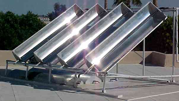
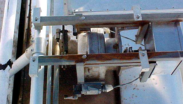
Patrick Rowe's system
Patrick Rowe is using an LED3XS24Vc1 variant. It has an external LED sensor. This tracker is driving an American Science & Surplus DC gear motor. In this case the gear motor is being tested for use with a trough solar hot water heater. I believe the motor turns at 1.6 RPM and consumes 300mA @ 12V.
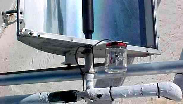
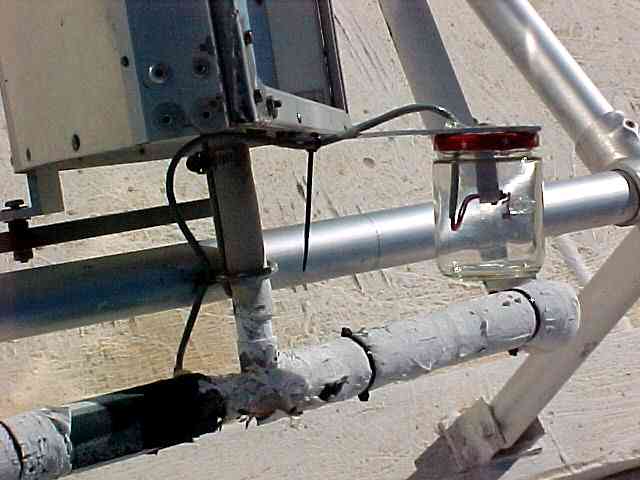
Insulated hot water piping and what looks to be a Kee Klamp frame. See:
 Kee Klamps
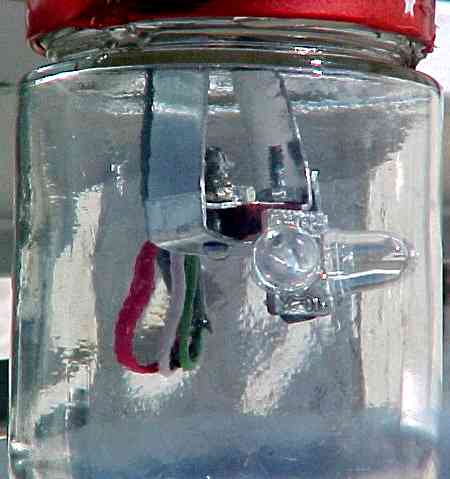
The glass baby food jar weather dome.
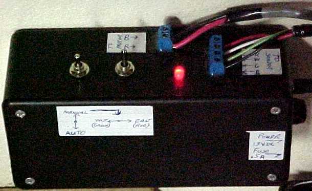
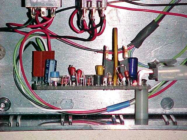
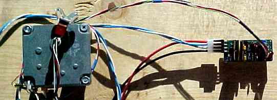
The control box which contains the LED3X and switches for manual operation.
Paul Pakelson's system

Wolfgang Schmidt's system
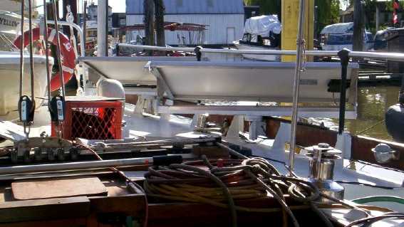
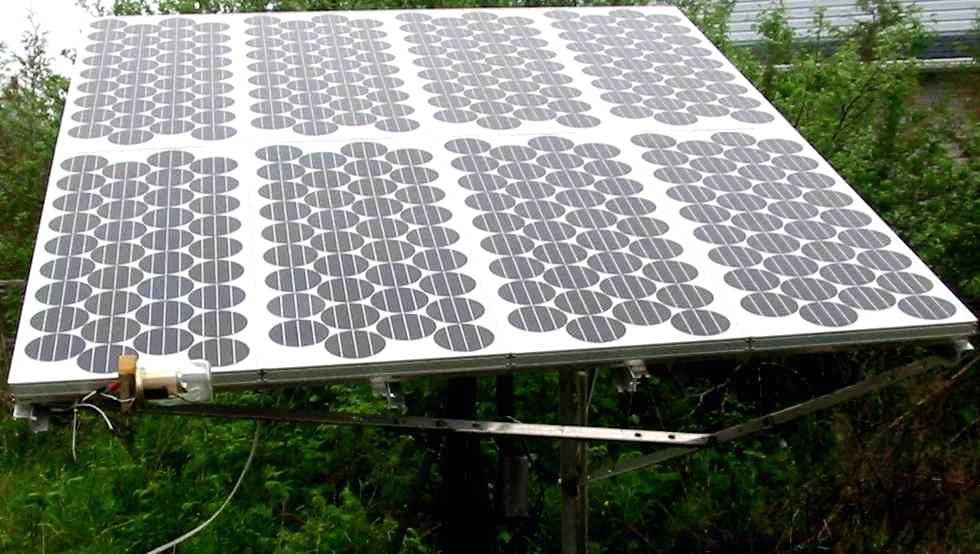
Wolfgang <wschmidt@smartt.com> is making track able solar panels for boats. He plans to sell them. Neat huh!
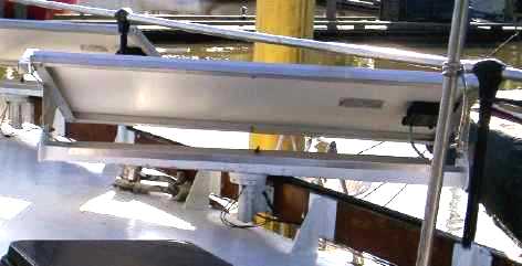
The vertical axis mount can turn 360 degrees. They are equipped with slip rings to bring the power to the boats battery charging system.
The solar trackers are the LED3XS24Vc1NP, $40us. These have been modified with the "no park" feature, (see below). This was required as the orientation of the boat changes constantly.
LED3Xc1 Modifications
Here are a couple of modifications.
1. If you don't want the tracker to park, possibly for the vertical axis on a 2 axis dish or a boat application as with Wolfgang.
2. The Reverse Lockout modification prevents moving in the oposite direction for about 50 seconds after an initial move. This is usefull for motor drives that move rapidly and tend to overshoot causing "hunting".